49
SPURS
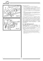
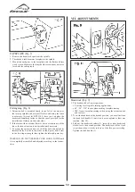
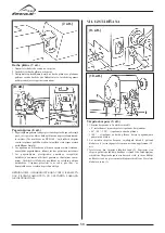
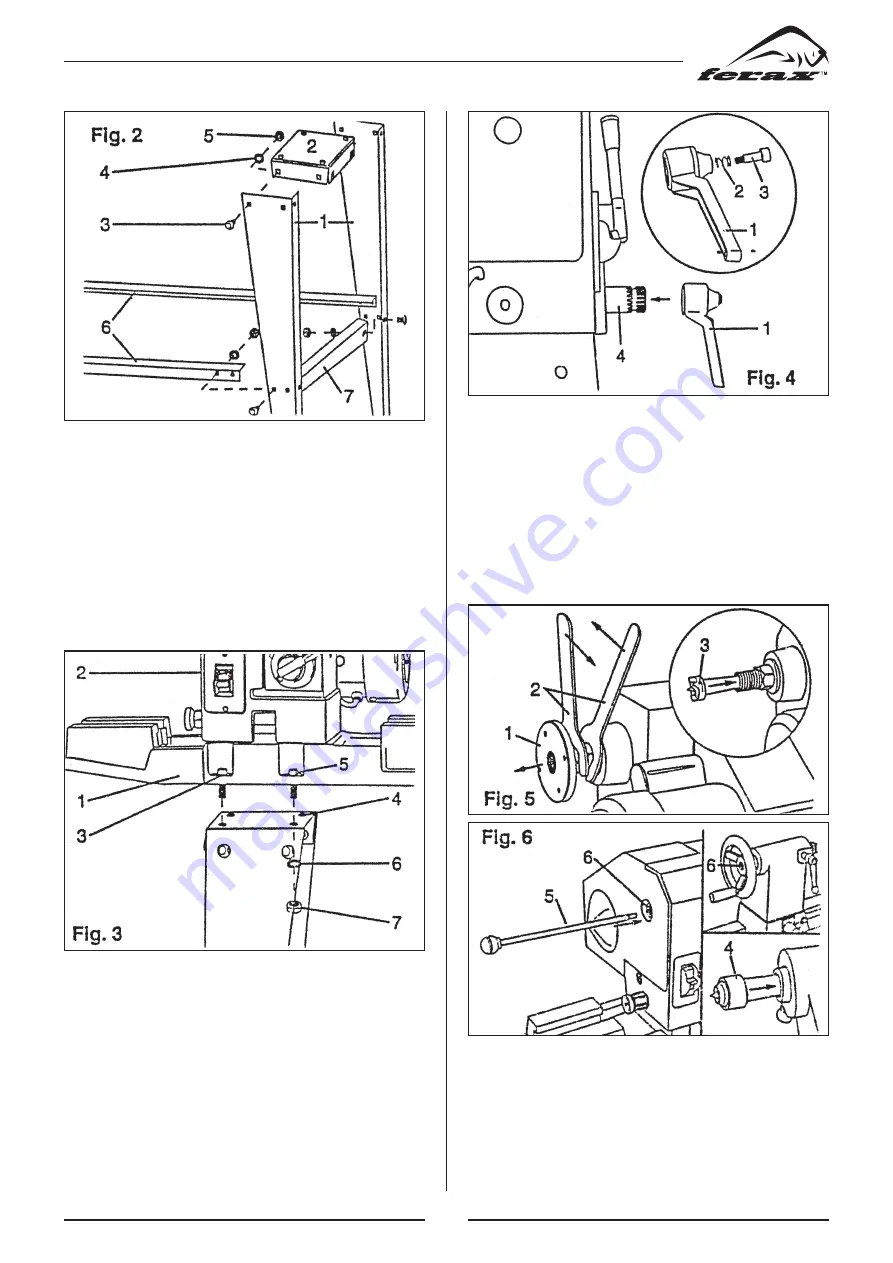
1. Remove the faceplate (1) from the headstock spindle using the
two wrenches provided(2) to separate the faceplate from the
spindle nut. (Fig. 5)
2.Insert the headstock spur (3) in the spindle hole.
3. Insert the live center(4) in the tailstock hole.(Fig 6)
4. To remove either the headstock spur or the tailstock center
insert end of the headstock or tailstock. Remove and store the
rod in a safe location after use.
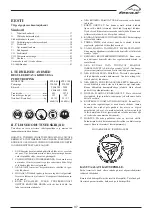
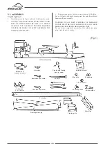
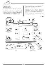
Erecting the leg set (Fig. 2)
1. Attach one front and one back leg(1) to the outside edge of the
top plate (2) using carrirage bolts (3), washers (4) and nuts(5).
2. Position the top plate so that it fits inside the legs.
3. Repeat step 1 for the opposite side.
4. Attach long supports(6) to legs using carriage bolts,washers,and
nuts.
5. Attach the short leg supports (7) on the legs with the carriage
bolt, washers and nuts.
6. Place the floor frame on a flat surface and tighten all nuts with
a 14mm wrench or adjustable wrench.
Note for BTS1100: Do not screw the tool rack (plate) with edges
upward.
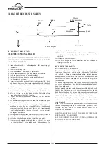
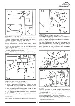
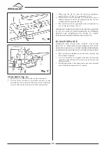
Setting the lathe on the leg set (Fig. 3)
1. Place the lathe bed assembly (1) on the leg set.
2. Position the headstock (2) assembly over the top plate and align
the holes in the bed(3) with the holes in the top plate (4). Set the
head stock down carefully.
3. Align the tailstock assembly end of the lathe over the top plate
mounting holes and set it down carefully.
4. Insert the hex bolts(5) into the mounting holes in each bed and
into the top plate.
5. Thread washer (6) and nut (7) onto bolt(5), and tighten securely.
IMPORTANT!
THE LEG SET MUST BE FASTENED TO THE SUPPORTING
SURFACE.
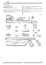
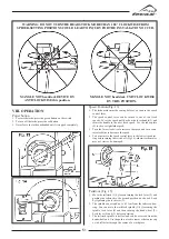
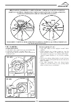
Lock the handle to the headstock (Fig. 4)
1. Assemble sets Parental lock handle (1), spring (2) and bolt (3)
in accordance with figure 4.
2. Wood is mounted on the handle locks the shaft (4) and tighten.
NOTE: Spring Loaded handles.
The spring-loaded handles are designed to be minimalist sera
interference with other parts lathe turnings or substance. Push the
hand lever and turn clockwise to tighten. When you release the
handle so it springs out of the pit tracked, so that you can rotate
the handle so that it is not in the road.
Summary of Contents for 10320-0101
Page 2: ......
Page 4: ......
Page 79: ...79 FTS 900 ...
Page 80: ...80 FTS 1100 ...
Page 84: ......
Page 85: ......
Page 86: ......
Page 87: ......


