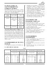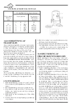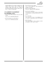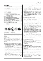
32
2.0 INSTALLATION
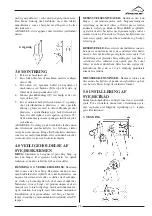
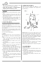
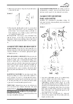
Connect the power supply cable (FIG.1A) to the
correct receptacle, single-phase 230V (protected by
slow blow fuses).
FIG. 1
• Make sure that telephones or TV, computers or other
control systems are not in the working area;
• People with pace-maker or hearing-prosthesis
should keep far from the power source.
! In particular cases special protection measures may
be required.
Interference can be reduced following these sugges-
tions:
• If there is interference in the power source line, an
E.M.T. filter can be mounted between the powersup-
ply and the power source;
• The output cables of the power source should be shor-
tened, kept together and connected to ground;
• After the maintenance all the panels of the power
source must be securely fastened in place.
1.7 ELECTRIC SHOCK
DANGER – ELECTRIC SHOCK CAN BE FATAL.
A qualified person first aid technique should always be
present in the working area.
If person is unconscious and electric shock is suspec-
ted, do not touch the person if he or she is in contact
with commands.
Disconnect power from the machine and then use First
Aid. Dry wood, and other insulating material can be
used to move cables, if
necessary, away from the person.
1.8 EMC
Before installing the unity, carry out an inspection of
the surrounding area, observing the following guide-
lines:
1. Make sure that there are no other power supply
cables, control lines, telephone leads or other equip-
ment near the unit.
2. Make sure that there are no radio receivers or televi-
sion appliances.
3. Make sure there are no computers or other control
systems.
4. Make sure there are no -one with a pacemaker or
hearing aid in the area around the unit.
5. Check the immunity of any other equipment opera-
ting in the same environment. In certain cases addi-
tional protective measures may be required.
Interference can be reduced in the following ways:
1. If there is interference in the power supply line, an
E.M.C. filter should be inserted between the mains
and the unit.
2. The output cables of the unit should be shortened;
these should be kept close together and stretched
along the ground.
3. All the panels of the unit should be correctly closed
after carrying out maintenance.
IMPORTANT: the wires of the supply cable of your
power source have the following colour codes: Yellow-
Green = Ground, Brown = Phase, Blue = Neutral. If the
colours of the wires of the power supply cable do not
match with the colour labels identifying the terminals
of your receptacle proceed as follows:
The green wire must be connected to the terminal iden-
tified by the letter E or by the ground symbol ( ) or with
yellow-green colour.
The brown wire must be connected to the terminal
identified by the letter L or with red colour.
Warning: this equipment must be connected to ground.
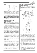
3.0 ASSEMBLY
1. Unpack the welder;
2. Screw the foot (D) to the machine using the screw
provided (E);
3. Insert the axle (A) through the holes at the rear of the
welderand slide a wheel (B) on to each end followed
by the retaining washers (C);
4. Assemble the plastic handle (F) using the screws
provided (G);

