background image

52

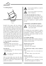
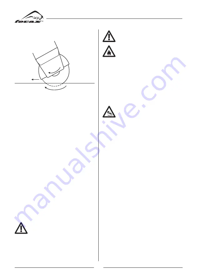
7.2 Cutting (Fig. 6)

Fig. 6

Maintain firm contact with the workpiece 

to prevent vibration and do not tilt or apply 

pressure and when cutting. Use moderate pres-

sure when working, appropriate to the material 

that is being worked on. Do not slow down 

grinding discs by applying sideways counter 

pressure. The direction in which you want to 

cut is important. The machine must always 

work against the direction of the cut; so never 

move the machine in the other direction! There 

is the risk that the machine will catch in the cut 

causing kickback and that you will lose control.

7.3 The ON/OFF/ switch (Fig. 1)

Switching on

•  Slide the ON/OFF switch forwards.

•  The  machine  will  start  and  keeps  engaged 

when releasing the switch.

Switching off

•  Press the ON/OFF switch: this will then jump 

to the OFF-position.

The grinder will continue to run after 

it is turned off.

Only lay the machine down once the motor 

has completely stopped turning. Do not put the 

machine on a dusty surface. Dust particles can 

penetrate the machine.

Never use the spindle key to stop the 

motor turning.

Never use the machine to grind mag-

nesium workpieces.

7.4 Carbon brush indicator (Fig. 1)

When the carbon brushes are worn this indi-

cator will light up. The cabon brushes need to 

the  be  replaced  by  the  manufacturer’s  custo

-

mer service department or equally qualified 

persons. 

8. SERVICE & MAINTENANCE

Make sure that the machine is not 

live when carrying out maintenance 

work on the motor.

The machines have been designed to operate 

over a long period of time with a minimum of 

maintenance. Continuous satisfactory opera-

tion depends upon proper machine care and 

regular cleaning.

8.1 Trouble shooting

Should the machine fail to function correctly, a 

number of possible causes and the appropriate 

solutions are given below:

Machine fails to operate.

•  Power turned off.

•  (Extension) cable damaged.

The elektromotor hardly reaches maximum 

speed.

•  The  extension  cable  is  too  thin  and/or  too 

long.

•  The mains voltage is lower than 230 V.

Machine overheats.

•  Air vents are blocked. Clean them with a dry 

cloth.

•  The  machine  has  been  overloaded.  Use  the 

machine for the purpose it is made for

Summary of Contents for BAG-900

Page 1: ...Manual Angle grinder Instruktionsbok Vinkelslip BAG 900 Code no 19694 1108 ...

Page 2: ...the instructions and make certain that the machine functions correctly Keep this operator s guide and other enclosed documentation with the machine The angle grinder is suitable for non professio nal use for cutting or separating materials Any other use is strictly forbidden 2 TECHNICAL SPECIFICATION Voltage V 230 Frequency Hz 50 Power input W 850 No load speed r min 11000 Disc diameter mm 125 Spi...

Page 3: ...is power tool Failure to follow all instructions listed below may result in electric shock fire and or serious injury Operations such as sanding wire brushing or polishing are not recommended to be per formed with this power tool Operations for which the power tool was not designed may create a hazard and cause personal injury Do not use accessories which are not specifi cally designed and recomme...

Page 4: ...d clear of the spinning acces sory If you lose control the cord may be cut or snagged and your hand or arm may be pulled into the spinning accessory Never lay the power tool down until the accessory has come to a complete stop The spinning accessory may grab the surface and pull the power tool out of your control Do not run the power tool while carrying it at your side Accidental contact with the ...

Page 5: ... and shape for your selec ted wheel Proper wheel flanges support the wheel thus reducing the possibility of wheel breakage Flanges for cut off wheels may be different from grinding wheel flanges Do not use worn down wheels from larger power tools Wheel intended for larger power tool is not suitable for the higher speed of a smaller tool and may burst 5 4 Additional safety warnings specific for abr...

Page 6: ...nce of another defect Carefully inspect the machine and grinding disc before switching the machine on again Make sure that sparks do not put people into danger or that they contact highly flammable substances Make sure that the workpiece is sufficiently supported or clamped Keep your hands away from the surface to be cut Always wear safety goggles and hearing pro tection If desired or required als...

Page 7: ...chine for left handed use Turn the hand grip 3 to the notch on the left side of the machine for right handed use Turn the hand grip to the notch on the top of the machine to use it vertically 6 2 Disassembly Remove the flange nut and the grinding disc with lower flange from the spindle Unscrew the 4 screws with washers en remove the fixing ring Remove the guard from the machine 6 3 Mounting a grin...

Page 8: ...e regula tions Hold the machine away from the workpiece when turning it on and off because the grinding disc could damage the workpiece Clamp the workpiece firmly or use another method to ensure that it cannot move while working Check the discs regularly Worn grinding discs have a negative effect on the machine s efficiency Change to a new grinding disc in good time Always first turn the machine o...

Page 9: ...face Dust particles can penetrate the machine Never use the spindle key to stop the motor turning Never use the machine to grind mag nesium workpieces 7 4 Carbon brush indicator Fig 1 When the carbon brushes are worn this indi cator will light up The cabon brushes need to the be replaced by the manufacturer s custo mer service department or equally qualified persons 8 SERVICE MAINTENANCE Make sure...

Page 10: ...and dirt If the dirt does not come off use a soft cloth moiste ned with soapy water Never use solvents such as petrol alcohol ammonia water etc These solvents may damage the plastic parts 8 3 Faults Should a fault occur e g after wear of a part please contact your reseller On the separately enclosed spare parts list you can find an over view of the parts that can be ordered 8 4 Environment To prev...

Page 11: ...81 BAG 900 DIAGRAM ...

Page 12: ... ring 5 1 21 Spring 1 22 Lock pin 1 23 Nut 1 24 Small bevel gear 1 25 Bearing 6000 1 26 Press plate of bearing 1 27 Screw M5 10 2 No Description Specification Qty 28 Rotor 1 29 Bearing 627 1 30 Bearing sheath 1 31 Wind screen 1 32 Cross screw ST4 75 2 33 Stator 1 34 Nameplate 1 35 Pushbutton 1 36 Pull pole 1 37 Side handle 1 38 Spring 2 39 Cross screw ST3 10 4 40 Inductor 2 41 Cross screw ST4 16 3...

Page 13: ...ARETE SUPPLIES S L www aretesupplies com Angle grinder BAG 900 ...

Reviews: