Ferax
57
Ajuste de la escuadra antidesgarro
Fig. 4
•
Coloque el soporte (12) en la cepilladora
•
Apriete la perilla (11)
•
Ajuste la escuadra sobre el soporte
•
Establezca el ancho de corte correcto y apriete la tuerca mariposa
4. CONSERVACIÓN Y MANTENIMIENTO
Extraiga siempre el enchufe de la toma de red antes de realizar trabajos de
conservación y mantenimiento.
La cuchilla de cepillado se desgasta después de un cierto tiempo de utilización. Si sigue
utilizando una cuchilla despuntada o deteriorada, verá Vd. reducida la eficacia de su trabajo, y
eventualmente podría sobrecargar el motor. Compruebe regularmente la cuchilla para
detectar posibles desgastes o deterioros; según su estado, será conveniente su sustitución.
Desmontaje de la cuchilla del cepillo
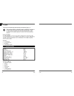
Fig. 3
Utilice la llave de boca anexa (accesorios). Primero, suelte con la llave de boca los tres tornillos
de apriete (6) y extraiga la cuchilla (3), la base de la cuchilla (2) y el soporte de la cuchilla (4) del
huso portador (1).
Montaje de la cuchilla de lcepillo
Fig. 3
Tome la nueva cuchilla (3) y colóquela entre el soporte de la cuchilla (4) y la base de la cuchilla (2).
Ahora enrosque los tornillos de apriete (6) en el soporte de la cuchilla tanto como sea posible. No
tanto como para que la cuchilla y su base vuelvan a soltarse del soporte de la cuchilla. A
continuación, introduzca conjuntamente la cuchilla, su soporte y su base en el huso portador.
Cuchilla, soporte y base son fijados ahora conjuntamente en el huso portador desenroscando
con la llave de boca los tornillos de apriete, inmovilizándose así cuchilla, soporte y base.
¡Atención!
Desenrosque los tornillos de apriete tanto como sea posible para garantizar así
una fijación suficiente.
¡Atención!
•
En los trabajos de montaje y desmontaje de la cuchilla, asegúrese de que todas las piezas
(cuchilla, base de la cuchilla, soporte de la cuchilla y huso portador) estén limpias. Deben
eliminarse suciedades y eventuales capas de suciedad.
•
Los tornillos inbus (5) están asegurados con cola. Estos tornillos no pueden regularse. El
reglaje de estos tornillos sólo puede ser llevado a cabo por el fabricante.
Compruebe regularmente que los tornillos de apriete estén bien sujetos.
Apriételos siempre bien fuerte.
ES
08
Ferax
4. CARE & MAINTENANCE
Before undertaking any care or maintenance always remove the mains plug from
the socket.
The planing tool becomes worn after a period of operation. If you use a blunt or damaged
planing tool operational efficiency is reduced and the electric motor might become overloaded.
Check the planing tool regularly with regard to wear or damage. Depending on its condition, the
planing tool will have to be replaced.
Removal of plane blade
Fig. 3
Use the enclosed open-jawed spanner (Accessories). First unscrew the three clamping
screws (6) with the open-jawed spanner and remove the plane blade (3), the plane blade holder
(2) and the plane blade support (4) from the holding shaft (1).
Installation of plane blade
Fig. 3
Take the new plane blade (3) and position it between the plane blade support (4) and the plane
blade holder (2). Now turn the clamping screws (6) as far as possible into the plane blade
support. But not so far that the plane blade and the plane blade holder become detached again
from the plane blade support. Afterwards put the plane blade, plane blade holder and plane
blade support together into the holding shaft. The plane blade support, plane blade and plane
blade holder will now be fastened together in the holding shaft by releasing the clamping
screws with the open-jawed spanner and thus the plane blade, plane blade support and plane
blade holder are clamped in position.
Attention!
Unscrew clamping screws as fas as possible so that a sufficient attachment is ensured.
Warning!
• When installing and removing the plane blade, care has to be taken that all parts (plane
blade, plane blade holder, plane blade support and holding shaft) are clean. Dirt or possible
existing layers of dirt have to be removed.
• The Allen screws (5) are secured with an adhesive. These screws must not be adjusted. The
position of these screws may only be altered by the manufacturer!
Check regularly if the clamping screws are tightened firmly. Always tighten screws
firmly.
Replacing the drive belt
Fig. 5
• Loosen screw (15) and take off the belt cover (16).
• Remove worn drive belt (17).
• Before assembling a new drive belt, clean both belt pulleys.
GB


