4
EN
ANGLE POLISHER 1400W - 180MM
Thank you for buying this Ferm product.
By doing so you now have an excellent product,
delivered by one of Europeís leading suppliers.
All products delivered to you by Ferm are
manufactured according to the highest standards
of performance and safety. As part of our
philosophy we also provide an excellent customer
service, backed by our comprehensive Warranty.
We hope you will enjoy using this product for many
years to come.
The numbers in the text refer to the diagrams
on pages 2-3.
Read this operators guide carefully,
before using the machine. Ensure that
you know how the machine works, and
how it should be operated. Maintain the
machine in accordance with the
instructions, and make certain that the
machine functions correctly. Keep this
operator’s guide and other enclosed
documentation with the machine.
Contents
1. Machine data
2. Safety instructions
3. Assembly
4. Use
5. Service & maintenance
Introduction
Any other use other than polishing and light
sanding is strictly forbidden.
1. MACHINE DATA
Technical specification
Voltage
220-240 V~
Frequency
50 Hz
Power input
1400 W
No-load speed
1000-3300/min
Disc diameter
180 mm
Spindle dimension
M 14
Weight
3.3 kg
Lpa (sound pressure)
86+3 dB(A)
Lwa (sound power)
97+3 dB(A)
Vibration value
3.51+1.5 m/s
2
Vibration level
The vibration emission level stated in this
instruction manual has been measured in
accordance with a standardised test given in
EN 60745; it may be used to compare one tool
with another and as a preliminary assessment of
exposure to vibration when using the tool for the
applications mentioned
- using the tool for different applications, or with
different or poorly maintainted accessories,
may significantly increase the exposure level
- the times when the tool is switched off or when
it is running but not actually doing the job, may
signifi cantly reduce the exposure level
Protect yourself against the effects of vibration by
maintaining the tool and its accessories, keeping
your hands warm, and organizing your work
patterns
Features
Fig. 1
1. On/off switch
2. Speed control
3. U-shaped handle
4. Pad holder
5. Spindle lock
6. Lock-on button
2. SAFETY INSTRUCTIONS
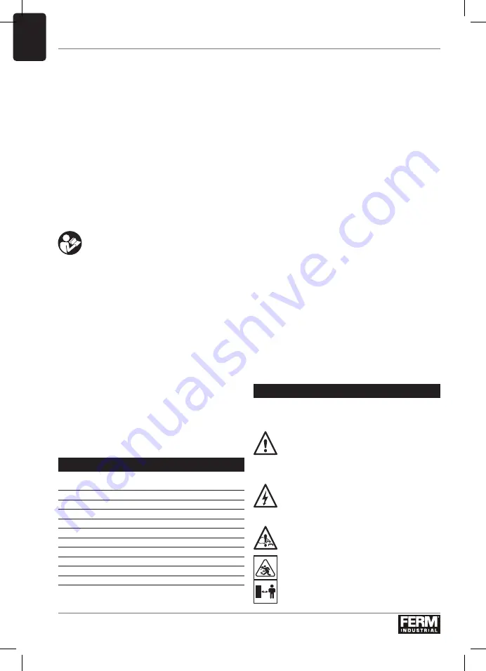
Explanation of the symbols
Denotes risk of personal injury, loss of life
or damage to the machine in case of non-
observance of the instructions in this
manual.
Indicates electrical shock hazard.
Immediately unplug the plug from the
mains electricity in the case that the cord
gets damaged and during maintenance.
Use spindle lock only in stand still mode.
Keep bystanders away.
Summary of Contents for AGM1120P
Page 2: ...2 Fig 1 Fig 2 Fig 3 3 5 4 1 6 2...
Page 3: ...3 Fig 4 Fig 5 Fig 6 A B 5 3 4...
Page 120: ...120 RU 180 M14 3 3 Lpa 86 3 A Lwa 97 3 A 3 51 1 5 2 EN 60745 1 1 2 3 U 4 5 6 2 O a b c...
Page 121: ...121 RU d e f g h i j k l m n o p...
Page 122: ...122 RU a b c d e 30...
Page 123: ...123 RU II 1 5 2 3 2 3 4 5 4 3 4 4...
Page 124: ...124 RU 5 6 1 1 6 1 1 6 1 5...
Page 125: ...125 UK 2012 19 EU 1400W 180mm 3 2 3 1 2 3 4 5 1 220 240 V 50 Hz 1400 1000 3300 180 M 14...
Page 126: ...126 UK 3 3 Lpa 86 3 A Lwa 97 3 A 3 51 1 5 2 EN 60745 1 1 2 3 U 4 5 6 2 a b c d e...
Page 127: ...127 UK f g h i j k l m n o p...
Page 128: ...128 UK a b c d e 1 5 2 30...
Page 129: ...129 UK 1 5 2 3 2 3 4 5 4 3 4 4 5 6 1 1 6 1 1 6 1...
Page 130: ...130 UK 5 2012 19 EU...
Page 132: ...132 EL l...
Page 133: ...133 EL...
Page 134: ...134 EL O 30 Zmax 0 348 Ohm...
Page 135: ...135 EL A H N II 1 5 mm2 3 2 3 4 5 4 3 A 4 4 5...
Page 136: ...136 EL 6 On Off 1 On Off 1 6 On Off 1 On Off 1 6 On Off 1 5 2012 19 EU...
Page 143: ...143 MK a b c c d max e f g 1 min h i j k...
Page 144: ...144 MK l m n o p a b c d e max max f...
Page 145: ...145 MK 30 s Zmax 0 348 1 5 mm2 3 2 3 5 5 4 3 4...
Page 146: ...146 MK 4 5 6 1 1 6 1 6 1 A 7 7 5...
Page 147: ...147 MK 2012 19 EU...
Page 149: ...149 Exploded view...
Page 150: ...150...
Page 152: ...WWW FERM COM 2020 FERM 2005 19...


