background image

EN

7

Ferm

 Make sure that the compressor is 

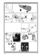
transported in the right way, do not turn it 

upside down and don’t lift it with hooks or 

ropes (fig. 5-6).

Starting up

Check whether the mains voltage corresponds 

• 

to that indicated on the electrical specification 

plate (fig. 10), the permitted tolerance range 

should be within 5%. 

Press the switch situated on the upper part 

• 

into the “0” position according to the pressure 

regulator type fitted on the device (fig. 11).

Put the plug in the plug socket (fig. 9) and start 

• 

the compressor up by putting the switch of the 

pressure regulator in the “I” position. The 

operation of the compressor is fully automatic. 

The pressure regulator will stop the 

compressor when the maximum value has 

been reached and start it up when the 

pressure drops below the minimum value. 

Normally the difference in pressure is approx. 

2 Bar/29 psi between the maximum and the 

minimum value. For instance - The 

compressor will stop when it reaches 8 Bar 

(116 psi) (this is the maximum operating 

pressure) and will start up automatically when 

the pressure within the tank has dropped to 6 

Bar (87 psi).

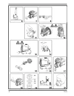
 The head/cylinder/transmission pipe 

assembly may reach high temperatures, 

so take care when working close to these 

parts and do not touch them to avoid 

burns (fig. 12 - 13). 

Adjusting the operating pressure

Fig. 14

It is not necessary continuously to use the 

maximum operating pressure, the compressed-air 

tools often require less pressure. With regard to 

compressors supplied with a pressure reduction 

valve it is necessary to set the operating pressure 

properly. 

It is possible to set the operating pressure by using 

the turning knob on the reduction valve. 

By turning clockwise, the pressure will be 

• 

increased.

By turning anti-clockwise, the pressure will be 

• 

reduced.

The set pressure can be locked by turning the ring 

under the turning knob in the opposite direction 

from the turning knob thereby fixing the turning 

knob. The set pressure is visible on the 

manometer of the reduction valve.

4. Maintenance

Make sure that the plug is removed from 

the mains when carrying out maintenance 

work on the motor. 

The machines have been designed to operate 

over a long period of time with a minimum of 

maintenance. Continuous satisfactory operation 

depends upon proper machine care and regular 

cleaning. Before interfering in any way whatsoever 

with the compressor, please make sure that:

The general line switch is in the “0” position.

• 

The pressure regulator and the switches on 

• 

the switch board are switched off in the “0” 

position.

The air tank is fully decompressed.

• 

Malfunction

Should the machine fail to function correctly, a 

number of possible causes and the appropriate 

solutions are given below:

Air loss

May be caused by a poor seal of a connection.

• 

Check all connections by wetting them with 

• 

soap and water. 

The compressor runs but does not compress 

Fig. 19

May be caused by the valves (C-C2) or a 

• 

gasket (B1-B2) being broken.

Replace the damaged part.

• 

The compressor will not start

If the compressor is difficult to start, check:

• 

whether the voltage of the mains corresponds 

• 

to that on the specification plate (fig. 10)

whether electrical extension cables are being 

• 

used with a faulty core or length.

whether the operating environment is too cold 

• 

(below 0°C).

whether there is electricity supply (plug 

• 

properly connected, magneto-thermal fuses 

not broken).

The compressor does not shut off

If the compressor does not shut off when the 

maximum pressure has been reached, the safety 

valve of the tank will be activated. It is necessary 

Summary of Contents for CRM1036

Page 1: ...al instructions 05 DE Übersetzung der Originalbetriebsanleitung 08 NL Vertaling van de oorspronkelijke gebruiksaanwijzing 13 FR Traduction de la notice originale 17 ES Traducción del manual original 21 HU Eredeti használati utasítás fordítása 25 ...

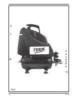
Page 2: ...2 Ferm Fig A ...

Page 3: ...3 Ferm Fig F ...

Page 4: ...4 Ferm ...

Page 5: ...nstructions Explanation of symbols Denotes risk of personal injury loss of life or damage to the tool in case of non observance of the instructions in this manual Risk of electric shock Caution the compressor could start automatically in case of a black out and subsequent reset Wear ear protection Sound power level Special safety instructions Warning The compressor may only be used in suitable roo...

Page 6: ...ried out by authorised Support Services or by other qualified centres Never forget that the earthing core is the green or the yellow green wire Never connect this green wire to a terminal under load Before replacing the plug of the feed make sure that the earth cable is connected If in doubt please call in a qualified electrician and have the earthing checked Electrical connection Always check whe...

Page 7: ...y turning clockwise the pressure will be increased By turning anti clockwise the pressure will be reduced The set pressure can be locked by turning the ring under the turning knob in the opposite direction from the turning knob thereby fixing the turning knob The set pressure is visible on the manometer of the reduction valve 4 Maintenance Make sure that the plug is removed from the mains when car...

Page 8: ... To prevent damage during transport the appliance is delivered in a solid packaging which consists largely of reusable material Therefore please make use of options for recycling the packaging Faulty and or discarded electrical or electronic apparatus have to be collected at the appropriate recycling locations Warranty The warranty conditions can be found on the separately enclosed warranty card K...

Page 9: ...n Den Luftstrahl nicht auf Personen oder Tiere richten Abb 20 Den Kompressor nicht transportieren wenn der Kessel unter Druck steht Vorsicht Einige Kompressorteile wie z B der Kopf und die Leitungen können hohe Temperaturen erreichen Um Brandwunden zu vermeiden diese Teile nicht berühren Abb 12 und 13 Zum Transport des Kompressors das Gerät anheben oder die speziellen Transportgriffe verwenden Abb...

Page 10: ...ktioniert 3 Benutzung Nur für den Heimgebrauch Vermerk Die Informationen in dieser Anleitung dienen dazu dem Bediener beim Gebrauch und bei der Wartung des Kompressors zu helfen Manche Abbildungen in dieser Anleitung können in Einzelheiten von Ihrem Kompressor abweichen Aufstellung Nachdem der Kompressor ausgepackt Abb 1 und auf einwandfreien Zustand sowie Transportschäden überprüft wurde muss Fol...

Page 11: ...indert Der eingestellte Druck kann festgesetzt werden indem man den Ring unterhalb des Drehknopfs in entgegengesetzter Richtung zum Drehknopf dreht sodass der Knopf fixiert wird Der eingestellte Druck wird auf dem Manometer auf dem Druckminderer angezeigt 4 Wartung Vergewissern Sie sich dass der Netzstecker gezogen ist während Sie Wartungsarbeiten am Motor ausführen Die Geräte wurden für Langzeitb...

Page 12: ...lt werden bei einer staubigen Arbeitsumgebung ist häufigeres Auswechseln erforderlich Der Kompressor erzeugt Kondenswasser das sich im Kessel sammelt Das Kondenswasser muss mindestens einmal pro Woche durch Öffnen des Ablasshahns unter dem Kessel Abb 16 aus dem Kessel abgelassen werden Vorsicht Wenn sich Druckluft im Inneren befindet kann das Wasser mit viel Kraft ausgestoßen werden Empfohlener Dr...

Page 13: ...kelaar 4 Reduceerventiel 5 Drukregelaar 6 Snelkoppeling Uitgang 7 Manometer Drukregelaar 8 Manometer Ketel 9 Veiligheidsventiel 10 Drukleiding 11 Aftapkraan 2 Veiligheidsvoorschriften Symbolenlijst Gevaar voor lichamelijk letsel of materiele schade wanneer de instructies in deze handleiding niet worden opgevolgd Gevaar voor elektrische schok Pas op De compressor kan bij stroomuitval en daaropvolge...

Page 14: ...e leiding niet te herstellen wanneer deze is beschadigd Elektrische veiligheid Aarding voorschriften Deze compressor moet geaard worden terwijl hij in gebruik is om de bediener te beschermen tegen elektrische schokken De compressor is voorzien van een tweepolige kabel plus aarde De elektrische verbinding moet uitgevoerd worden door een gekwalificeerd technicus Wij raden aan nooit de compressor te ...

Page 15: ... druk naar het minimum niveau zakt Normalerwijze is het verschil in druk ongeveer 2 bar 29 psi tussen de maximum en de minimum waarde Bv De compressor stopt als hij 8 bar 116 psi bereikt max werkdruk en start automatisch als de druk in de tank gedaald is tot 6 bar 87 psi Na de compressor aangesloten te hebben door de stekker in het stopcontact te steken de tank tot de maximum druk vol te pompen en...

Page 16: ... Gebruik geen oplosmiddelen als benzine alcohol ammonia etc Dergelijke stoffen beschadigen de kunststof onderdelen Smering Het is aan te raden elke 50 werkuren het aanzuigfilter te demonteren en het filterelement schoon te maken door middel van perslucht fig 15 Één maal per jaar dient het luchtfilterelement te worden vervangen als de compressor in een schone omgeving werkt en vaker als de omgeving...

Page 17: ... Bouchon de vidange 2 Règles de sécurité Explication des symboles Indique un risque de blessures un danger mortel ou un risque d endommagement de l outil en cas du non respect des consignes de ce mode d emploi Indique un risque de décharges électriques Attention le compresseur est susceptible de redemarrer automatiquement en cas de black out et retablissement successif de la tension Utiliser un di...

Page 18: ...être mis à la terre pendant l utilisation pour ne pas exposer l utilisateur au risque d un choc électrique Le compresseur est équipé d un câble à deux âmes plus un fil de terre Le branchement électrique doit être effectué par un technicien qualifié Nous déconseillons de jamais démonter du compresseur ainsi que de brancher d autres connexions sur le régulateur de pression Les réparations doivent êt...

Page 19: ...en dessous de 6 bar L ensemble piston cylindre tuyau de transmission peut atteindre des températures très élevées si vous travaillez à proximité de ces pièces faites attention à ne pas les toucher pour ne pas vous brûler fig 12 13 Réglage de la pression de fonctionnement Fig 14 Il n est pas nécessaire d utiliser toujours la pression de fonctionnement maximum étant donné qu une pression moindre suf...

Page 20: ...ts peuvent abîmer les pièces en plastique Lubrification Il est recommandé de démonter le filtre d aspiration toutes les 50 heures de fonctionnement et de nettoyer le filtre à l air comprimé fig 15 Il est recommandé de remplacer le filtre au moins une fois l an lorsque le compresseur fonctionne dans un environnement propre et plus souvent à mesure l environnement est plus poussiéreux Le compresseur...

Page 21: ...n 8 Manómetro tanque 9 Válvula de seguridad 10 Tubo de presión 11 Llave de desagüe 2 Normas de seguridad Explicación de los símbolos Indica peligro de sufrir descargas eléctricas Retire el enchufe de la toma de corriente Atencion El compresor puede volver a arrancar automáticamente en caso de interrupción generalizada de la corriente y tras da mesma Utilice un mecanismo para proteger los oídos Niv...

Page 22: ...o El compresor está provisto de un cable de dos hilos con tierra La conexión eléctrica debe ser ejecutada por un técnico cualificado Recomendamos no desensamblar nunca el compresor ni hacer ninguna otra conexión en el regulador de presión Todas las reparaciones deberán ser ejecutadas por Servicios de Soporte autorizados o por otros centros cualificados No olvide nunca que la masa es el cable verde...

Page 23: ...ínimo Por lo general la diferencia entre la presión máxima y mínima es de 2 Bar 29 psi aproximadamente Por ejemplo El compresor se detendrá cuando alcance 8 Bar 116 psi esta es la presión máxima de funcionamiento y volverá a ponerse en marcha automáticamente cuando la presión en el tanque se haya reducido a 6 Bar 87 psi La unidad compuesta por cabezal cilindro tubo de transmisión puede alcanzar al...

Page 24: ...ilice un paño suave humedecido con agua con jabón Nunca utilice disolventes como gasolina alcohol amoniaco etc ya que estas sustancias pueden dañas las piezas de plástico Lubricación Se recomienda retirar el filtro de succión tras cada 50 horas de funcionamiento y limpiar la unidad del filtro soplándola con aire comprimido fig 15 Se recomienda que la unidad del filtro sea sustituida al menos una v...

Page 25: ...Biztonsági útmutatások A szimbólumok jelentése Arra figyelmeztet hogy a jelen kézikönyvben lefektetett biztonsági előírások be nem tartása szermélyi sérüléshez halálos balesethez vagy a szerszám károsodásához vezethet Áramütés veszélye Vigyázat áramszünet után a kompresszor automatikusan beindulhat Viseljen hallásvédőt Zajszint Speciális biztonsági előírások Figyelmeztetés A kompresszor csak arra ...

Page 26: ...ztasson a nyomásszabályzó csatlakoztatásán Javítást csak szakszerviz vagy más képzett szerviz végezhet a kompresszoron Ne feledje hogy a zöld vagy a sárga zöld vezeték a földelő vezeték Ezt a zöld vezetéket terhelés alatt soha ne csatlakoztassa a terminálhoz Mielőtt a dugaszt újból a konnektorra dugaszolná bizonyosodjon meg arról hogy a földelő vezeték be van kötve Ha ebben nem biztos ellenőriztes...

Page 27: ...sának irányában forgatva a nyomás növekszik A gombot az óramutató járásával ellentétes irányban forgatva a nyomás csökken A forgatógomb alatt elhelyezett gyűrűnek a gombbal ellentétes irányú forgatásával a gomb és azáltal a beállított nyomás rögzíthető A beállított nyomás a nyomáscsökkentő szelep nanométerén leolvasható 4 A gép karbantartása Mielőtt a motoron karbantartást végez mindenképpen húzza...

Page 28: ...te cserélni ha a kompresszort tiszta környezetben használja ha poros környezetben üzemelteti ajánlatos ennél gyakrabban cserélni A kompresszorban lecsapódó víz a tartályban gyűlik össze A lecsapódott vizet legalább hetente kell a tartályból leereszteni a tartály alatt elhelyezett leeresztőcsap 16 ábra kinyitásával Legyen óvatos amikor sűrített levegő van a palackban mert a víz képes erővel kitörni...

Page 29: ...n Position 706018 Gasket set 14 17 19 706027 Filter 16 706019 Drain cock 33 706020 Rubber feet 34TILL37 706021 Quick coupling 38 706022 Reduce valve 39 706023 Manometer 40 706024 Connection piece 41 706025 Safety valve 42 706026 Automatic pressure switch 43 ...

Page 30: ...30 Ferm Exploded view ...

Page 31: ...ovědnost prohlašujeme že je tento výrobek v souladu s následujícími standardy a normami SK Vyhlasujeme na našu výhradnú zodpovednosť že tento výrobok je v zhode a súlade s nasledujúcimi normami a predpismi SL S polno odgovornostjo izjavljamo da je ta izdelek v skla du in da odgovarja naslednjim standardom terpredpisom PL Deklarujemy na własną odpowiedzialność że ten produkt spełnia wymogi zawarte ...

Page 32: ... 2010 Ferm B V 1106 06 ...

Reviews: