8
EN
a) Health defects resulting from vibration
emission if the power tool is being used
over longer period of time or not adequately
managed and properly maintained.
b) Injuries and damage to property to due to
broken accessories that are suddenly dashed.
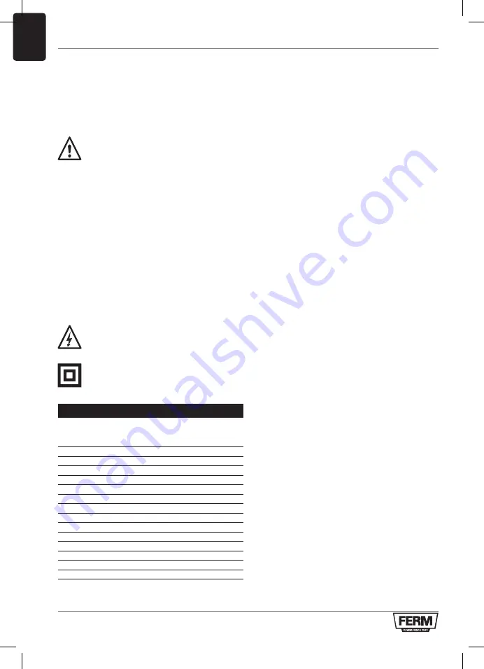
Warning!
This power tool produces an
electromagnetic field during operation.
This field may under some circumstances
interfere with active or passive medical
implants. To reduce the risk of serious or
fatal injury, we recommend persons with
medical implants to consult their
physician and the medical implant
manufacturer before operating this
power tool.
Electrical safety
When using electric machines always observe the
safety regulations applicable in your country to
reduce the risk of fire, electric shock and personal
injury. Read the following safety instructions and
also the enclosed safety instructions.
Always check that the voltage of the
power supply corresponds to the voltage
on the rating plate label.
Class II machine - Double insulation -
You don’t need any earthed plug.
2. MACHINE INFORMATION
Technical specifications
Battery CDA1106
Charger CDA1107
Input of charger
220-240V~ 50/60Hz 1.2A
Output of charger
21V DC, 2.2A
Battery charging time
60 min
Telescopic pole
1000-1150 mm
Pole angle adjustment
0° - 90°
Head adjustable
0° - 90°
No load speed
8.000/min
Cutting diameter
220 mm
Cutting system 2 line wire spool, Tap and go Ø1.2mm x 5m
Weight (incl battery)
2.1 kg
Sound pressure level LPA
71.2 dB(A) K=3 dB(A)
Sound power level LWA
88.2 dB(A) K=3 dB(A)
Vibration value
6.918 m/s
2
K=1.5 m/s
2
Vibration level
The vibration emission level stated in this
instruction manual has been measured in
accordance with a standardized test given in
EN60745; it may be used to compare one tool
with another and as a preliminary assessment of
exposure to vibration when using the tool for the
applications mentioned.
• Using the tool for different applications, or with
different or poorly maintained accessories,
may significantly increase the exposure level.
• The times when the tool is switched off or when
it is running but not actually doing the job, may
significantly reduce the exposure level.
Protect yourself against the effects of vibration by
maintaining the tool and its accessories, keeping
your hands warm, and organizing your work
patterns.
Description
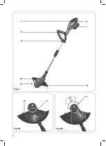
The numbers in the text refer to the diagrams on
pages 2-5
Fig. A tm E
1. Battery
2. Battery unlock button
3. Battery charge indication
4. Charger
5. Charger LED indicators
6. On/off switch
7. Safety switch
8. Front handle
9. Front handle knob
10. Protection guard
11. Screw
12. Guardrail
13. Side wheel
14. Side wheel holder
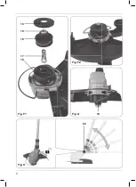
Fig. F tm J
15. Spool cover
16. Spool reel
17. Spool spring
18. Spool housing
19. Tip spool reel
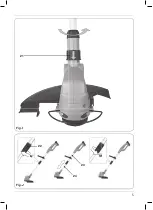
20. Adjustment knob trimmer head
21. Adjustment ring trimmer head
22. Lower adjustment ring
23. Upper shaft
24. Lower shaft
Summary of Contents for GTM1003
Page 2: ...2 Fig B1 Fig B2 Fig A 1 14 6 11 12 10 7 8 9 10 12...
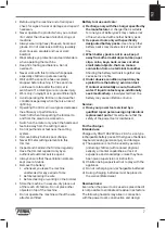
Page 3: ...3 Fig D2 Fig E Fig C1 Fig C3 Fig D1 Fig C2 14 8 13 8 9 3 1 4 2 1 5 1...
Page 4: ...5 4 3 2 1 4 Fig F1 Fig F2 Fig G Fig H 18 20 19 15 19 16 17...
Page 5: ...5 Fig I Fig J 22 23 24 21...
Page 24: ...24 Exploded view...
Page 26: ...WWW FERM COM 2019 FERM 1911 01...


