background image

5

ECC+ 230 V Electronic Module

INPUTS


Output relay


An


output relay is provided to give continuous information to the main lift controller 

concerning the status of the doors. 

18 / 19 / 20 

Open.


Relay activated when the doors are fully open.

42 / 43 / 44 

Closed.


Relay activated when the doors are fully closed. 


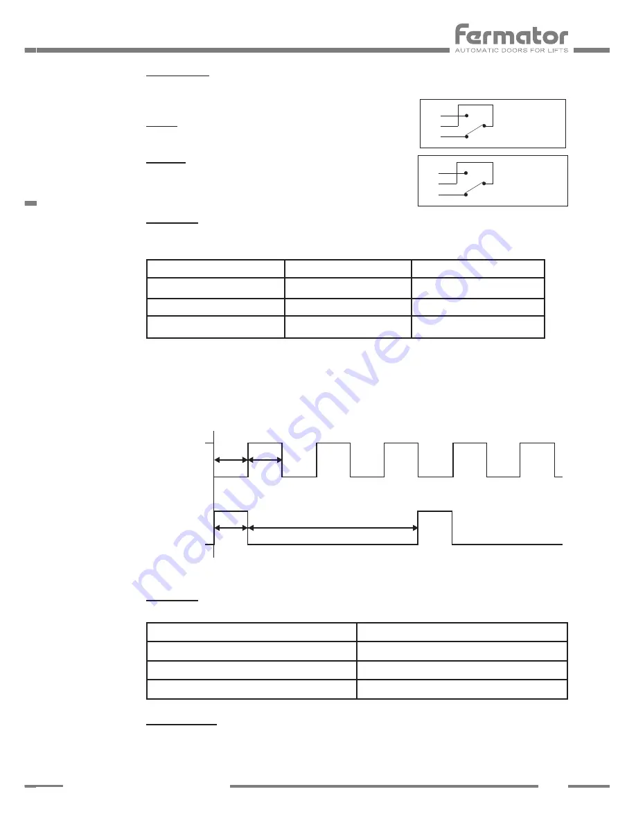
LED INDICATORS:


Ok status.


Green LED indicates proper working conditions.


Depending on how the ECC + 230 V is powered the green LED lights up in different ways:

12 V battery

230 V power supply

Ok Status LED

Lit

Blinking

Single flash


– LED lit: constantly on.


– LED blinking: iso-phase on and off with a frequency of approximately 5 Hz: on for 


  approximately 100 ms followed by off for approximately 100 ms.


– LED single flash: one short flash (approximately 100 ms) followed by a long off phase 


  (approximately 2.400 ms).


Ok status.


LED indicates the status of the door.

Door Status

Open / Closed LED colour

Door fully open

Lighting green

Door fully closed

Lighting red

Alarm activated

Lighting orange

21 / 22 / 23


Serial switch.


Serial switch connection. Direct connection between the entrance and the exit without 

any influence in the electrical circuit function. 


20

18
19

OPEN

44

42
43

CLOSED

Indicator states and flash rates

Blinking

Single 

flash

100

100

2.400

ms

ms

ms

ms

100

on

on

off

off

Summary of Contents for ECC+ 230 V

Page 1: ...MAN MUED00000ENGTC 12 2017 ENG User manual Automatic horizontal sliding car door Component ECC 230 V Electronic Module...

Page 2: ...WITCH CONTACTO SEGURIDAD SAFETY SWITCH REABRIR 2 REOPEN 2 REABRIR 1 REOPEN 1 SE AL DE PISO FLOOR LEVEL F C CERRAR CLOSE L S CON ENCODER WITH ENCODER ABIERTA CERRADA OPEN CLOSED OK STATUS SPECIAL ESPEC...

Page 3: ...FCE ON Heavy door The motor supplies a 30 extra torque to be able to move heavy doors OFF Standard door Standard control is applied to perform the door movement 4 Floor level Inputs 12 V battery ON 2...

Page 4: ...This supply must only be used for this purpose b This contact must be isolated from any other power supply 12 Close signal This signal is used for ordering to close the door 13 14 Floor level This inp...

Page 5: ...D lit constantly on LED blinking iso phase on and off with a frequency of approximately 5 Hz on for approximately 100 ms followed by off for approximately 100 ms LED single flash one short flash appro...

Page 6: ...a power stage with a current limiting protection The 24 V DC motor incorporates a thermal protection in order to inform the lift controller in case of motor overheating Once the thermal protection is...

Page 7: ...signal is necessary to check that the car door s is are in the closed position To comply with this point an additional door contact is added and the signal has to be connected to the lift controller T...

Page 8: ...sultant damage produced in the equipment described in this manual and associated installation if the instructions given have not been followed TECNOLAMA reserves the right to modify the product or spe...

Reviews: