AUTOMATIC DOORS FOR LIFTS
4
VF5
4
Master and Slave.
ON:
Master.
The door control unit will execute instructions directly. Example: photocell activation will
cause the doors to re-open immediately without control of the door control unit.
OFF:
Slave.
There is no automatic reopen movements. The doors will only react to instruction given
by the main lift controller. Example: with the photocell activated the unit will send a signal
to the main lift controller via the PHOTOCELL output (36, 37, 38). Then, the main lift
controller must remove the close signal and put the open signal.
5 / 6 / 7
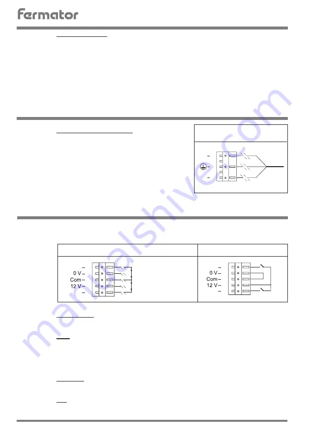
230 Volts single phase AC.
The circuit has been designed to operate on a
mains supply of 230 V AC (+10%,-15%, 50 or 60
Hz). The unit will consume approx 1 Amp from
the supply.
It is important that the Door Operator Module
has a GOOD EARTH CONNECTION.
The circuit can work with external voltage inputs or internal voltage input
(voltage free contact).
8
Close signal.
This signal is used for ordering to close the door.
9
12 V.
Isolated 12 V output available to control the door via a voltage free contact.
Features are:
a)This supply must only be used for this purpose.
b)This contact must be isolated from any other power supply.
10
Common.
Is the reference used for the opening and closing signal.
11
0 V.
Is the opposite pole to 12 V, in the case of using internal voltage it should be connected
to common input.
N
L
230 V
5
6
7
POWER INPUTS CONNECTIONS
CONTROL INPUTS
POWER INPUTS
12
11
10
9
8
EXTERNAL VOLTAGE INPUTS
Open
Close
Voltage
12 V DC...60 V DC,
100 V AC...230 V AC.
OPEN
Voltage
12 V DC...60 V DC,
100 V AC...230 V AC.
CLOSE
12
11
10
9
8
INTERNAL VOLTAGE INPUTS
Open
Close
OPEN
CLOSE
PROGRAMMING


