background image

25

VF7

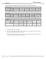
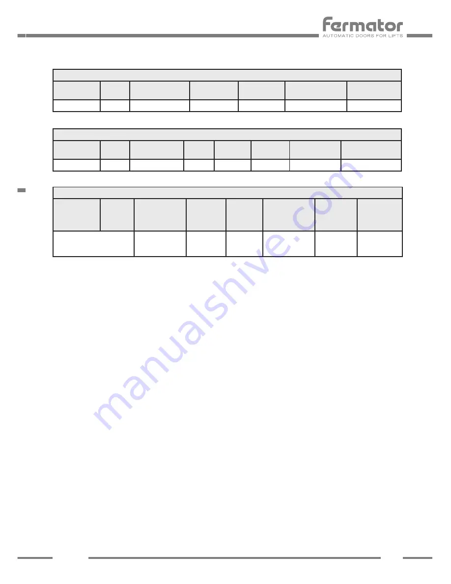
Door to be calculated:

Model

Opening

Number of panels

PL [mm]

HL [mm]

Panel type

Fire protection

Premium PM

Side

1

800

2.000

Double skin

F.R. E120

Taking as basis(1):

Model

Opening

Number of panels

PL [mm]

HL [mm]

Panel type

Fire 

homologation

Moving mass [Kg]

Premium PM

Side

2

800

2.000

Metal Sheet

F.R. E120

36,61

Calculations:

Difference per 

opening

Difference 

per 

number of 

panels

Difference per PL

(each 100 mm)

Difference 

per HL

(each 100 

mm)

Difference 

per panel 

type

Difference per 

fire homologation

SUM

Moving mass

36,61 x (-0,17) = -6,13 Kg

There are

equals

There are

equals

36,61 x 

0,12 = 4,39 

Kg

There are

equals

4,39 – 6,13 = 

-1,74 Kg

36,61 – 1,74 = 

34,87 Kg

1.    These specifications are in the Annex 1.

2.    This factor is the difference between T2 (side 2 panels) to T1 (side 1 panel). There is the number 2  

       of the second table of Premium PM in the Annex 1.

3.    This factor is the difference between metal sheet panel and double skin panel. There is the number  

       11 of the second table of Premium PM in the Annex 1

Example 2: Difference of opening and number of increment of PL and HL.

ANNEX 2

Summary of Contents for VF7

Page 1: ...ENG User manual Automatic horizontal sliding car door Component VF7 Electronic Module V7 01 02 MAN MU00000V7ENGTC 12 2017 ...

Page 2: ...57 58 59 47 45 43 41 39 37 35 33 31 46 42 44 40 36 38 34 30 32 12 9 10 11 8 OK STATUS EMISOR EMITTER RECEPTOR RECEIVER CERRAR LENTO SLOW CLOSE OUT 12 V REABRIR RE OPEN CONTACTO DE BYPASS BYPASS CONTACT SEÑAL DE PISO FLOOR LEVEL ABIERTA OPEN CERRADA CLOSED FOTOCÉLULA PHOTOCELL OBSTRUCCIÓN OBSTRUCTION BARRERA FOTOELÉCTRICA LIGHT CURTAIN BARRERA FOTOELÉCTRICA LIGHT CURTAIN TEMPERATURA TEMPERATURE ABR...

Page 3: ...ring to close the door With an external voltage input the tension to apply could be from 12 V DC to 60 V DC or 100 V AC to 230 V AC between this input and common 10 With an internal voltage input the tension applied is 12 V DC between this input and Out 12 V 9 9 12 VOLT Isolated 12 Volts output available to control the door through a voltage free contact Features are a This supply must only be use...

Page 4: ...te the Fermator photocell It is composed by a emitter and receptor infrared 21 26 PRIORITY INPUTS 21 REOPEN This signal is used for installing the cabin door switch an external barrier or other devices In order to active this signal connect the re open input 21 with the 12 V 23 Use voltage free contacts The reopening signal has priority over the closing signal 22 LIGHT CURTAIN This input is used t...

Page 5: ...D indicator and relay activated when the doors are fully open Closed LED indicator and relay activated when the doors are fully closed and locked Photocell LED indicator and relay activated when the photocell or the reopening input is operated Obstruction LED indicator and relay activated when an obstacle is detected that stops the doors from closing The signal will reset when the doors reach the ...

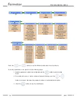
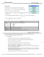
Page 6: ...n objectives can be achieved with the VF7 graphic interface 1 To detect possible alarms or errors in the unit Alarms Menu 2 To see the parameters value and active signals Monitor Menu 3 To modify the internal program parameters and options Programming Menu Once the unit is connected it will show the software version Fermator V7 01 02 Push the button to a access to the VF7 menus There are four main...

Page 7: ...ption Hard obstacle in clearance Check the mechanical part Push the OK button Low Volt The power supply voltage is under 15 V AC The external power supply could be damaged Check the external power supply Push the OK button or increase the power supply voltage more than 15 V AC Memory The memory is failing The VF could have some internal problems Replace the VF7 Push the OK button Friction The door...

Page 8: ...or could have a high friction The VF7 metal cover could not be making good contact Check the mechanical part Tighten the screws of the metal cover Check that the VF is installed on a metal surface The alarm is disabled when the VF7 reach 70ºC Motor Temp Crit The motor coil has reached 140ºC The VF7 stops the normal operation The door could have a high friction The door could be blocked during the ...

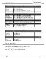
Page 9: ...submenu Push the button to return to the VF7 menus MONITOR MENU Push the button to see the different parameters Monitor Parameters Parameter Description Units Supply Voltage Voltage supply in AC V V RMS VF7 Temperature Temperature in the power module area ºC ºC Supply Type AC or DC supply or or ...

Page 10: ...arameter Description Units Open Door Status of the door open signal Closed Door Status of the door closed signal Re open Status of the Re open signal Obstruction Status of the obstruction signal Curtain Error Status of the light curtain signal Temperature Error Status of the temperature signal Monitor Door Parameter Description Units Position Position of the door in m indicating the zero point wit...

Page 11: ...r of times that the Motor overtemperature alarm has been activated VF7 Crit Overtemp Number of times that the VF7 critical overtemperature alarm has been activated Motor Crit Overtemp Number of times that the Motor critical overtemperature alarm has been activated Op Obstructions Number of obstructions in the opening movement Cl Obstructions Number of blockages in the closing movement Manoeuvre Fa...

Page 12: ...n option to do the following steps 1 Select de parameter option to be modify and push the button to enter in modify mode 2 The parameter value or option status will appear blinking push the or button to increase decrease the parameter value or enable disable the option 3 Push the button to save the modification or ...

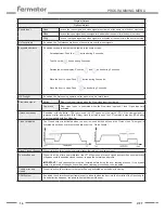
Page 13: ...troller via the Reopen output 36 37 38 Then the main lift controller must remove the close signal and active the open signal Landing Door Automatic Operators with Clutch automatic landing door In this case a special movement is made for locking and unlocking the Clutch Semiautomatic Operators without Clutch Semiautomatic landing door Rotation Sense Clockwise CW During the opening movement the moto...

Page 14: ...ctivated Unlock on standby If enabled with the clutch CDL fully closed the VF7 opens only the clutch CDL if the closing signal is removed or after a delay time Eco Delay Once the clutch is open the VF7 remains in standby This option is not compatible with Eco Mode No Close Anticipated The Closed output is activated when the door is closed but doesn t need the Clutch close This signal is activated ...

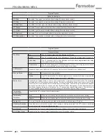
Page 15: ...Curtain Light Curtain installed The blocked signal must be connected to Re open input and the failure signal must be connected to Light Curtain input Barrier timer If enabled an intelligent timer is used in case of photocell or curtain permanent obstruction The protection is disabled after 2 minutes permanently blocked If a physical obstruction happens during the next closing movement the VF reope...

Page 16: ...ocess has to be done without charge Never perform calibration with the car door and landing door Program Parameters Parameters speeds Parameter Description Units Min Max Open Initial Speed The initial speed at opening m s 0 025 0 100 Close Initial Speed The initial speed at closing m s 0 025 0 100 Open Proximity Speed The approximation speed at opening m s 0 025 0 100 Close Proximity Speed The app...

Page 17: ...uired space to open close the Clutch m 0 000 0 100 Additional Clutch Movement Additional clutch movement to personalize the opening distance in emergency mode m 0 0 2 Pinion Perimeter Perimeter of the motor pinion m 0 001 1 000 Backstep length Length of the backwards movement Obstruction Backstep option m 0 010 0 150 Program Control Test Makes a door open or close cycle to verify proper operation ...

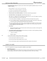
Page 18: ...ked INSTALLATION PROCESS The whole installation process has to been done when a new circuit is installed on a door If the circuit is already installed only do steps 9 and 10 Connections Connect the motor wire and encoder wire 55 56 57 58 59 If it has been installed connect the Fermator photocell 17 18 19 20 Disconnect all other inputs and outputs Connect the 230 V AC mains supply to the controller...

Page 19: ...se after a short delay From the information obtained the microprocessor will calculate the acceleration and deceleration ramps and the braking torque required to give the optimum control of the doors Door Test Active the Test option to open the door and verify the proper operation Active again the test option to close the door Program the VF7 control behaviour this options are located in the Progr...

Page 20: ...F7 programming menu In order to comply the standard is necessary to configure some options and parameters LIGHT CURTAIN The light curtain is mandatory and it can be connected to the lift controller or to the VF7 in the pin 22 LIFT STANDARD EN 81 20 50 Menu Option Configuration to comply EN81 20 50 Programming options Door model Select door model Photoc Curtain timer Enable Eco Mode Select modes Co...

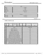
Page 21: ...are in the closed position To comply this point an additional door contact is added and the signal should be connected to the lift controller The maximum contact rating is 2 A 230 V AC REFERENCE DATA Power supply AC voltage range 230 V AC 10 15 Frequency supply 50 60 Hz Standby power 0 05 A 4 W Nominal power 0 21 A 20 W Inverter Carrier frequency 16 KHz Frequency range 0 5 100 Hz Voltage range 40 ...

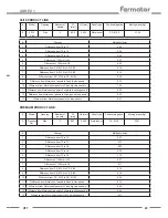
Page 22: ...ce of 100 mm in HL 0 01 4 Difference from F R E120 to F R EI60 0 16 5 Difference from F R E120 to F R EI120 0 20 6 Difference from F R E120 to F R EW60 0 12 7 Difference from F R E120 to F R E30 Russia 0 00 8 Difference from F R E120 to F R EI60 Russia 0 16 9 Difference from F R E120 to F R EI60 Ukraine 0 16 10 Difference from Metal sheet panels to Wien type vision panels 0 28 11 Difference from M...

Page 23: ... from Metal sheet panels to Flush big vision panels 1 02 11 Difference from Metal sheet panels to Full glass in skirting panels 0 95 12 Difference from Metal sheet panels to Wien type vision panels 0 32 13 Difference from Metal sheet panels to Vision panels 0 61 Concept Multiplier factor 1 Difference from T2 to T3 0 07 2 Difference from T2 to T1 0 17 3 Difference from T2 to C2 0 03 4 Difference fr...

Page 24: ...HL mm Panel type Fire homologation Moving mass Kg 40 10 PM Side 2 800 2 000 Metal sheet F R E120 31 93 Calculations Difference per opening Difference per number of panels Difference per PL each 100 mm Difference per HL each 100 mm Difference per panel type Difference per fire homologation SUM Moving mass There are equals There are equals 31 93 x 0 07 2 2 23 Kg 31 93 x 0 03 3 0 95 Kg There are equa...

Page 25: ... mm Difference per panel type Difference per fire homologation SUM Moving mass 36 61 x 0 17 6 13 Kg There are equals There are equals 36 61 x 0 12 4 39 Kg There are equals 4 39 6 13 1 74 Kg 36 61 1 74 34 87 Kg 1 These specifications are in the Annex 1 2 This factor is the difference between T2 side 2 panels to T1 side 1 panel There is the number 2 of the second table of Premium PM in the Annex 1 3...

Page 26: ......

Page 27: ...e following E U council directive Norm EN 81 1 2 DIRECTIVE 2006 42 EC Machinery directive DIRECTIVE 2014 30 EU Electromagnetic compatibility of the European Parliament and of the Council VF7 Electronic Module 15 31709299 Tecnolama S A Ctra Constantí Km 3 43204 REUS Spain Reus 11 12 2017 David Román General Manager ...

Page 28: ...oduced in the equipment described in this manual and associated installation if the instructions given have not been followed TECNOLAMA reserves the right to modify the product or specifications in this technical brochure without prior notification Tecnolama S A Ctra Constantí Km 3 43204 REUS Spain Tel 34 977 774 065 Fax 34 977 771 615 www fermator com e mail info es fermator com ...

Reviews: