Page 8
VDS iLoft Kit
VDS iLoft Kit
VDS iLoft Kit
VDS iLoft Kit
VDS iLoft Kit
VDS iLoft Kit
VDS iLoft Kit
VDS iLoft Kit
VDS iLoft Kit
VDS iLoft Kit
DESCRIPTION OF EQUIPMENT
Outdoor panel
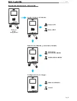
10º
10º
10º
10º
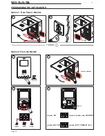
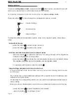
Pan&Tilt (
±
10º)
A)
Configuration Switches:
JP2
: Main Panel/Secondary Panel Selection.
Default Configuration: Main Panel
JP3
: Leds iluminación cámara
Main Panel
Secondary Panel
Leds ON
Leds OFF
VDS
PACK EXTENSION
CN1
AMPLIFICATEUR - AMPLIFIER
AMPLIFICADOR - VERSTÄRKER
PROG
SW1
CN3
STATUS
EXIT
NO
NC
C
JP3
JP2
LANGUAGE
IDIOMA
L
+ -
M
V
+12
C
NC
NO
-
BS
S
CT
ALIMENTACION
POWER SUPPLY
18 Vdc
- +
JP4
LEDS ON
SLAVE
MASTER
LEDS OFF
10
PAN & TILT
18V
DC
MONITOR TEST
CN7
CN1
DL2
CN2
SW1
CN3
MIC
AUDIO
JP2
JP3
JP4
CT OUT
CT IN
B
D
A
C
E
ON
CAM
DL2
CN2
TARJETERO
TAG HOLDER
VERSION
:
A)
B)
C)
G)
H)
E)
F)
J )
D)
K )
L )
M)
I )
JP4
: Camera activation/auxiliary output
CT:
11 Vdc output
CT: input
Connect 12 Vdc to permanetly
activate leds
E)
Focus the camera
:
B)
CN1:
Connection call extension module or up to 3 buttons.
C)
CN2: Connection cardholder and button lighting.
L+ / L-:
Cardholder Backlight.
CP:
Common button wire.
D)
DL2: Diagnostic Led.
If there is a short circuit b y L, when a call is made from the panel, it emits a series of
short flashes.


