background image

FERNO/MAN/1121/226-R3/UK

21

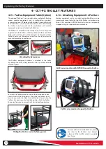
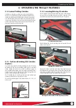
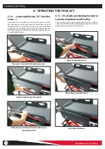
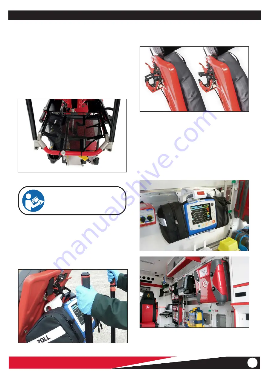
5.22 - Backrest Defib Monitor Hook

A defib monitor can be hooked to the rear of the backrest whilst 
moving the trolley outside of the ambulance in scenarios where 
the patient is not recumbent on the trolley. Simply place the 
monitor onto the hook and close by pulling the fixing bar down 
until it clicks in place,  ensuring that the fixing pin is located in 
the fixing pin hole. To remove, pull pin out, lift the fixing bar and 
remove  the monitor.

Zoll X-Series defib held on backrest hook

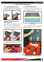
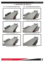
5.21 - Head-End Storage Net (Option)

A storage net is available for CCT-PX, which attaches to the trolley 
frame at the head-end below the backrest, allowing lightweight 
items such as documents and patient's belongings to be stowed 
whilst moving a patient outside of the ambulance. 
For safety reasons it should not be used for storage of items whilst 
travelling inside an ambulance. All equipment and articles inside 
the back of a vehicle must be safely secured on an appropriate 
crash-tested bracket or in a cupboard to avoid them becoming a 
projectile in the event of a vehicle crash. 

Storage net on head-end trolley frame

6 - OPERATING THE TROLLEY

Operating the Trolley

For more information on the head-end 
storage net please also refer to the Storage 
Net User Manual, reference 234-3590-01, 
which is available from Ferno.

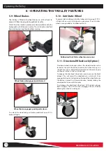
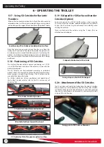
Note that the backrest hook is not designed to hold equipment 
whilst moving in a vehicle. It is only intended  as a place to 
temporarily hold the monitor when transferring a patient from 
scene of incident to vehicle, and then once at destination, 
from out of the vehicle to hospital admissions. When inside the 
ambulance, any equipment must be moved off the backrest 
holder and placed in a CEN complaint crash-tested bracket, such 
as on the PacRac equipment platform or Ferno's IPTS iNTRAXX 
wall track and equipment bracket system. 

 Ferno's IPTS iNTRAXX wall track bracket system

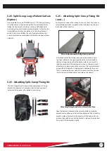
Hook and fixing bar on backrest

Pull side button to release fixing pin

Summary of Contents for CCT-PX

Page 1: ...rs Manual FERNO MAN 1121 226 R3 UK Stock Code 2003 0158 Read this Manual and Retain for Future Reference Photo showing CCT PX configured with various available options Ferno CCT PX Critical Care Troll...

Page 2: ...r safety measures taken by the user should be within and under consideration of applicable regulations and local protocol Training on the proper use of this product must be provided before using this...

Page 3: ...ing SX Cotsides________________17 18 5 15 SX Cotside Positioning for Patient Lateral Transfer__ 18 5 16 SX Cotside Ratcheting Positions________________ 19 5 17 Using SX Cotsides for Bariatric Transfer...

Page 4: ...se refer to service manual for instructions Trapping hazards are unavoidable in any design of Trolley due to its folding action Operate with care Safety Information WARNING Do NOT exceed the safe work...

Page 5: ...ged labels immediately New labels are available from your distributor 1 7 Symbol Glossary The symbols defined below are used on the trolley and or in this user manual Ferno uses symbols recognised by...

Page 6: ...2 Training Operator trainees need to Have followed a training plan Read and understand the instructions in this manual Practice using the fully equipped trolley with weight and under simulated condit...

Page 7: ...lack Orange webbing Cross strap patient harness straps quick and easy to deploy Lateral folding cotsides Easy to operate lift assisted backrest and leg position platform Trendelenburg Shock Knee Conto...

Page 8: ...ole and then tighten the pole clamp fully Once tightened recheck that the device is indeed correctly attached A number of specialist brackets for a range of medical devices are available from Ferno fo...

Page 9: ...inciple as a belt buckle It is important that the straps are fully tightened at all times when a cylinder is located in the holder To remove the cylinder loosen the holder straps and then remove the c...

Page 10: ...Oxylog 3000 ventilator can be attached to the trolley To attach simply push the unit into the mounting bracket until it locks in place To release pull down the metal flap under the unit and then pull...

Page 11: ...avoid it lifting up out of place Attaching the IV pole to trolley side rail For more information on the 3 stage IV Pole please also refer to the 3 stage IV pole User Manual reference 00271 AU V01 whic...

Page 12: ...y When PacRac is not in use the poles can be left on the trolley or can be removed according to preference The PacRac equipment platform is attached to the trolley by sliding it onto the fixing points...

Page 13: ...orm allowing devices to be viewed at all times when moving patients instead of mounting these devices underneath the trolley The various medical device mounts can be supplied either with a swivel moun...

Page 14: ...the desired angle by squeezing the lever and pushing down on the leg platform The end section of the leg platform can be positioned at any angle to achieve the required leg position from horizontal t...

Page 15: ...and push down until it locks in place Make sure it is correctly locked in place by trying to pull the headrest back out The red slide button located at the base of the headrest on the rear of the bac...

Page 16: ...l lock push brake pedal back up until it is horizontal again Wheel brake engaged pedal points down Wheel brake disengaged pedal raised 5 11 Directional Wheel Lock Option Directional wheel lock option...

Page 17: ...tient sizes and which also ratchet to near horizontal giving an extended patient surface for larger bariatric patients with even larger physical body mass The SX cotsides have 3 ratchet positions plus...

Page 18: ...locked in place Moving SX cotside whilst depressing lever Bring SX cotside past horizontal Release lever and move SX cotside back up to required position 6 OPERATING THE TROLLEY Operating the Trolley...

Page 19: ...ical position 1 10o SX cotsides ratchet position 2 27 5o 5 16 SX Cotside Ratcheting Positions SX cotsides ratchet position 4 62 5o SX cotsides in near horizontal position 80o SX cotsides folded fully...

Page 20: ...point of SX Surface Xtenders 6 OPERATING THE TROLLEY 5 18 Positioning of SX Cotsides The Surface Xtender cotsides normal positioning on CCT PX is such that the head end side of the cotside is in line...

Page 21: ...e All equipment and articles inside the back of a vehicle must be safely secured on an appropriate crash tested bracket or in a cupboard to avoid them becoming a projectile in the event of a vehicle c...

Page 22: ...ed to side Pull towards end of trolley to unlock then pull towards you to unfold Unfold fully until clicks in place Side handles ready for use 5 24 Manoeuvring Handles Option Available as an option ar...

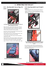
Page 23: ...des are placed in the fully down position on both sides of the stretcher SX cotsides moved to fully down position 5 25 Attaching Split Scoop Fixing Kit cont At the foot end of the trolley place one of...

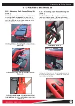
Page 24: ...nd of the trolley and the head end of the Scoop at the foot end of the trolley as per the below picture This ensures maximum usable extended patient surface Lock the bracket in place by pressing down...

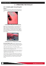
Page 25: ...end bracket Connect Scoop halves at head end with extension fixing pole Attaching 2 halves of Scoop together using extension fixing pole Operating the Trolley Features 5 25 Attaching Split Scoop Fixin...

Page 26: ...ice lever in full up position locked IMPORTANT BEFORE USING Re check all 4 locking levers on the fixing brackets to make sure they are fully down and that the fixing arms are securely locked to the tr...

Page 27: ...applied to the trolley 2 Place the trolley beside the patient and undo the patient straps moving them away from the area the patient will be lying 3 Ensure that the backrest is in the required positio...

Page 28: ...r side of the trolley Repeat the same for the other Crossover strap Repeat the same for the other Crossover strap and then adjust the length of straps using the adjust buckles so the Cross Strap harne...

Page 29: ...when the straps are adjusted to shortest length If the straps have been adjusted longer they can be clipped into the corresponding buckle on that side to avoid hanging down to the floor Adjustable ext...

Page 30: ...hind the backrest 7 PREPARING TO TRANSPORT A PATIENT Preparing to Transport a Patient 7 8 Attaching a Child Harness PediMate Neomate Unlike traditional tubing framed trolleys such as Pegasus the lower...

Page 31: ...be attached to CCT PX by first attaching one of these fixing tangs to each of the blue fixing straps supplied with the ACR harness as per below photos The ACR blue fixing strap is looped through and a...

Page 32: ...stud at base of backrest either side of the trolley 7 11 Using BabyPod on CCT PX Please refer to the BabyPod user manual for the procedure for attaching and using BabyPod on a trolley CCT PX can be us...

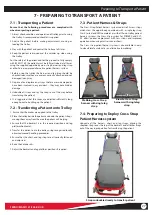
Page 33: ...sferring on and off a vehicle via a tail lift or ramp 1 Transporting a patient on the trolley should always be carried out with the cotsides raised and the Cross Strap harness and leg strap fastened a...

Page 34: ...ARING TO MOVE THE TROLLEY Preparing to Move the Trolley Head end lock spike fixing U bracket Foot end lock fixing bracket 9 1 Locking Devices 2 Part Lock Locking devices available for use with CCT PX...

Page 35: ...ontact time Ferno recommends you inspect the trolley for damage as you clean and disinfect it See note regarding disinfectants to use 1 Remove the mattress patient harness straps and any accessories 2...

Page 36: ...0 3182 Split Scoop Extreme Bariatric extended patient surface kit 009008250 Inflatable sidepads kit for use with Split Scoop kit 23271000802 Trolley dust cover elasticated AB material 836353200 AB Pat...

Page 37: ...and legs straps all present and properly installed Are the patient straps mattress and harness in good condition with no cuts or frayed edges Are patient strap buckles free of visible damage and do t...

Page 38: ...FERNO MAN 1121 226 R3 UK 38...

Page 39: ...12 months Below is a service schedule sheet where servicing dates and activities can be recorded Ferno UK offers a range of cost effective servicing programmes helping to keep your equipment in good c...

Page 40: ...FERNO MAN 1121 226 R3 UK 40...

Reviews: