FERNO/MAN/1121/226-R3/UK
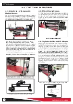
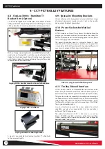
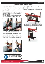
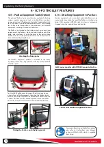
22
6 - OPERATING THE TROLLEY
Operating the Trolley
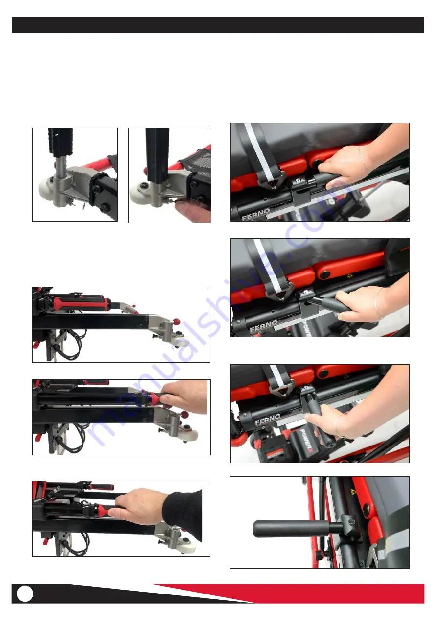
CCT-PX is supplied with 2 push poles as standard, with the option
of an additional 2 more push poles as required. These lock into
place on the corners of the trolley and are removed by deploying
the push pole detachment mechanism. A release pin is situated
behind and below the push pole which when pulled open allows
the push pole to be removed.
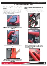
Insert push pole until it
locks into place
Release by pulling out
the locking pin located
behind the push pole
holder
5.23 - Push Poles
Side manoeuvring handles attached to side
Pull towards end of trolley to unlock, then pull
towards you to unfold
Unfold fully until clicks in place
Side handles ready for use
5.24 - Manoeuvring Handles (Option)
Available as an option are side-fixing manoeuvring handles, which
attach to the side of the trolley. These fold out when required and
aid the manoeuvring of the trolley from the side, beneficial for
example when navigating over rough terrain..
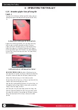
When removed, the push poles can be stored in the frame of the
trolley.
Push poles store discreetly inside the frame
Lift the cover at the end of the frame and introduce the push pole
into the hole, ensuring the push pole is parallel with the frame
Push the push pole all the way in until the raised end cap locks
into the fixing collar at the handle-end of the push pole.
Summary of Contents for CCT-PX
Page 38: ...FERNO MAN 1121 226 R3 UK 38...
Page 40: ...FERNO MAN 1121 226 R3 UK 40...

