background image

SKY F

11

EN

cod. 3540Z105  -  Rev. 01 - 01/2018

3.3 Plumbing connections
Important

B

Before making the connection, check that the unit is arranged for operation with
the type of fuel available and carefully clean all the system pipes.

Carry out the relevant connections according to the cover diagram and the symbols giv-
en on the unit .

System water characteristics

In the presence of water harder than 25° Fr (1°F = 10ppm CaCO

3

), use suitably treated

water in order to avoid possible scaling in the water heater.

3.4 Gas connection

The gas must be connected to the respective union (see figure on cover) in conformity
with the current regulations, with a rigid metal pipe or with a continuous flexible s/steel
tube, installing a gas cock between the system and water heater . Make sure all the gas
connections are tight.

3.5 Electrical connections
Important

B

BEFORE CARRYING OUT ANY OPERATION THAT REQUIRES REMOVING
THE CASING, DISCONNECT THE BOILER FROM THE ELECTRIC MAINS
WITH THE MAIN SWITCH.
NEVER TOUCH THE ELECTRICAL COMPONENTS OR CONTACTS WITH
THE MAIN SWITCH TURNED ON! THERE IS A DANGER OF ELECTRIC
SHOCK WITH THE RISK OF INJURY OR DEATH!

B

The unit must be connected to an efficient grounding system in accordance with
current safety regulations. Have the efficiency and suitability of the grounding
system checked by professionally qualified personnel; the Manufacturer de-
clines any liability for damage caused by failure to ground the system.
The water heater is prewired and has a "Y" type cable (without plug) for con-
nection to the electric line. The connections to the grid must be made with a per-
manent connection and equipped with a double-pole switch with contact gap of
at least 3 mm, interposing fuses of max. 3A between the water heater and the
line. Make sure to respect the polarities (LINE: brown wire / NEUTRAL: blue
wire / GROUND: yellow-green wire) in the connections to the electric line.

B

The unit's supply cable 

MUST NOT BE REPLACED BY THE USER

If the ca-

ble gets damaged, turn the unit off and have the cable replaced only by
professionally qualified personnel.

 In case of replacement, only use cable

“HAR H05 VV-F”

 3x0.75 mm2 with max. external diameter of 8 mm.

3.6 Fume ducts

B

THE BOILER MUST BE INSTALLED IN PLACES THAT MEET THE FUNDA-
MENTAL REQUIREMENTS FOR VENTILATION. OTHERWISE THERE IS A
DANGER OF SUFFOCATION OR INTOXICATION.
READ THE INSTALLATION AND MAINTENANCE INSTRUCTIONS BE-
FORE INSTALLING THE UNIT.
ALSO FOLLOW THE DESIGN INSTRUCTIONS

.

Important

The unit is a "C type" with sealed chamber and forced draught, the air inlet and fume out-
let must be connected to one of the following extraction/suction systems. The unit is ap-
proved for operation with all the 

Cny

 flue configurations given on the dataplate. Some

configurations may be expressly limited or not permitted by law, standards or local reg-
ulations. Before installation, check and carefully follow the instructions. Also, comply with
the instructions on the positioning of wall and/or roof terminals and the minimum distanc-
es from windows, walls, ventilation openings, etc.

Baffles

Unit operation requires fitting the baffles supplied. Make sure the right baffle (when used)
is fitted and correctly positioned.

A

 Baffle replacement with 

unit not installed

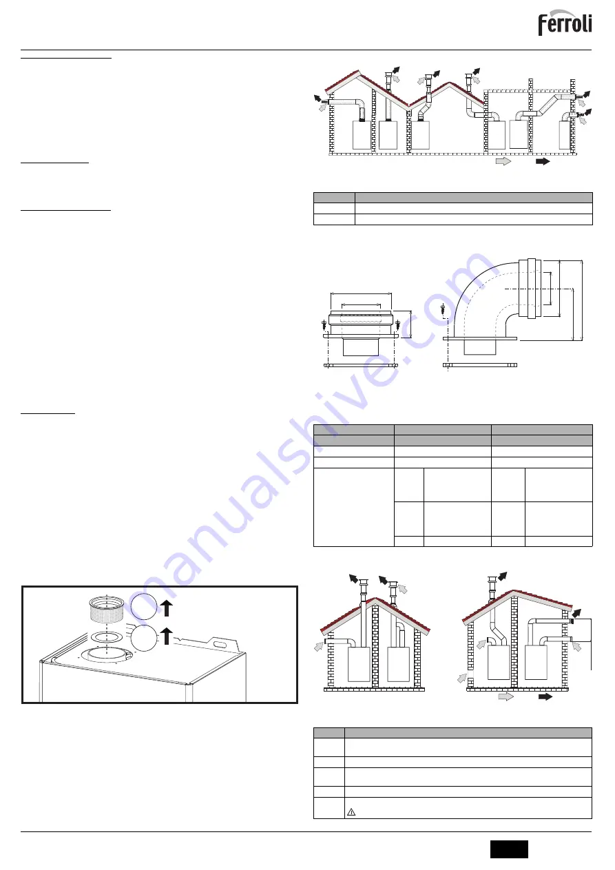
Connection with coaxial pipes

fig. 5 - Examples of connection with coaxial pipes (

 = Air / 

 = Fumes)

Table. 1 - Typology

For coaxial connection, fit the unit with one of the following starting accessories. For the
wall hole dimensions, refer to the figure on the cover.

fig. 6 - Starting accessory for coaxial ducts

Table. 2- Baffles for coaxial ducts

Connection with separate pipes

fig. 7 - Examples of connection with separate pipes (

 = Air / 

 = Fumes)

Table. 3 - Typology

A

1

2

Type

Description

C1X

Wall horizontal exhaust and inlet

C3X

Roof vertical exhaust and inlet

Coaxial 60/100

Coaxial 80/125

Max. permissible length

4 m

10 m

Reduction factor 90° bend

1 m

0.5 m

Reduction factor 45° bend

0.5 m

0.25 m

Baffle to use

0 ÷ 2 m

Model

SKY F 11

 = Ø43

SKY F 14

 = Ø47

SKY F 17

 = Ø47

0 ÷ 3 m

Model

SKY F 11

 = Ø39

SKY F 14

 = Ø47

SKY F 17

 = Ø47

2 ÷ 3 m

Model

SKY F 11

 = Ø43

SKY F 14

 = Ø50

SKY F 17

 = Ø50

3 ÷ 6 m

Model

SKY F 11

 = Ø43

SKY F 14

 = Ø50

SKY F 17

 = Ø50

3 ÷ 4 m

 NO BAFFLE

6 ÷ 10 m

 NO BAFFLE

Type

Description

C1X

Wall horizontal exhaust and intake. The inlet/outlet terminals must be concentric or close enough to be 
undergo similar wind conditions (within 50 cm)

C3X

Roof vertical exhaust and intake. Inlet/outlet terminals like for C12

C5X

Wall or roof  exhaust and intake separate or in any case in areas with different pressures. The exhaust 
and intake must not be positioned on opposite walls.

C6X

Intake and exhaust with separately certified pipes (EN 1856/1)

B2X

Intake from installation room and wall or roof exhaust

 IMPORTANT - THE ROOM MUST BE PROVIDED WITH APPROPRIATE VENTILATION

C

1X

C

1X

C

3X

C

3X

C

3X

C

1X

010006X0

010007X0

68

11

8

100

60

45.6

100

60

C

5x

C

3x

B

2x

C

1x

max 50 cm

Summary of Contents for SKY 11 F

Page 1: ... 2018 SKY F 595 E A 11 F 14 F 17 F A mm 295 335 375 C D B E mm 210 250 290 Modello 195 200 118 C B D 40 50 50 27 IT ISTRUZIONI PER L USO L INSTALLAZIONE E LA MANUTENZIONE EN INSTRUCTIONS FOR USE INSTALLATION AND MAINTENANCE ...

Page 2: ...a funzione anomalia combustione 10 Connessione Service Tool Indicazione durante il funzionamento Durante la richiesta sanitario generata dal prelievo d acqua calda sanitaria il display part 5 fig 1 visualizza l attuale temperatura d uscita dell acqua calda sanitaria Anomalia In caso di anomalia vedi cap 4 4 il display part 5 fig 1 visualizza il codice di guasto e durante i tempi di attesa di sicur...

Page 3: ...NE LEGGERE LE ISTRUZIONI DI INSTALLAZIONE E DI MANUTENZIONE PRI MA DI INSTALLARE L APPARECCHIO RISPETTARE ANCHE LE INTRUZIONI DI PROGETTAZIONE Avvertenze L apparecchio è di tipo C a camera stagna e tiraggio forzato l ingresso aria e l uscita fumi devono essere collegati ad uno dei sistemi di evacuazione aspirazione indicati di seguito L apparecchio è omologato per il funzionamento con tutte le con...

Page 4: ...attivare la modalità TEST Lo scaldabagno si accende al massimo della potenza sanitario imposta ta come al paragrafo successivo Sul display verrà visualizzata la potenza sanitario fig 9 Modalità TEST potenza sanitario 100 Premere i tasti part 1 e 2 fig 1 per aumentare o diminuire la potenza Minima 0 Massima 100 Per disattivare la modalità TEST premere contemporaneamente i tasti part 1 e 2 fig 1 per...

Page 5: ... causano blocchi temporanei contraddistinte con la lettera F che ven gono ripristinati automaticamente non appena il valore rientra nel campo di funziona mento normale dello scaldabagno Lista anomalie Tabella 6 fig 10 Valvola gas A Presa di pressione a monte B Presa di pressione a valle I Connessione elettrica Valvola gas R Uscita gas S Entrata gas fig 11 Connessione valvola gas TYPE SGV100 Pi max...

Page 6: ...ORIA GAS G20 II2H3B P CATEGORIA GAS G31 II2H3 Portata termica max kW 21 7 26 9 32 9 Q Portata termica min kW 8 3 10 3 12 6 Q Potenza Termica max kW 19 2 23 9 29 2 Potenza Termica min kW 7 1 8 8 10 7 Rendimento Pmax 88 5 88 7 88 9 Ugelli bruciatore G20 n x Ø 10 x 1 25 12 x 1 25 14 x 1 25 Pressione gas alimentazione G20 mbar 20 0 20 0 20 0 Pressione gas max al bruciatore mbar 13 0 14 0 15 0 Pression...

Page 7: ...Ž Ěŝ ĞŶĞƌŐŝĂ ĞůĞƚƚƌŝĐĂ ŽŶƐƵŵŽ ĂŶŶƵŽ Ěŝ ĞŶĞƌŐŝĂ ĞůĞƚƚƌŝĐĂ ĨĨŝĐŝĞŶnjĂ ĞŶĞƌŐĞƚŝĐĂ Ěŝ ƌŝƐĐĂůĚĂŵĞŶƚŽ ĚĞůů ĂĐƋƵĂ ŽŶƐƵŵŽ ŐŝŽƌŶĂůŝĞƌŽ Ěŝ ĐŽŵďƵƐƚŝďŝůĞ ŽŶƐƵŵŽ ĂŶŶƵŽ Ěŝ ĐŽŵďƵƐƚŝďŝůĞ ŵƉŽƐƚĂnjŝŽŶŝ Ěŝ ƚĞŵƉĞƌĂƚƵƌĂ ƚĞƌŵŽƐƚĂƚŽ ƋƵĂůĞ ĐŽŵŵĞƌĐŝĂůŝnjnjĂƚŽ ŝǀĞůůŽ ĚĞůůĂ ƉŽƚĞŶnjĂ ƐŽŶŽƌĂ Ăůů ŝŶƚĞƌŶŽ ŵŝƐƐŝŽŶŝ Ěŝ ŽƐƐŝĚŝ Ě ĂnjŽƚŽ DĂƌĐŚŝŽ ZZK dŝƉŽ Ěŝ ƉƌŽĚŽƚƚŽ ĐĂůĚĂĐƋƵĂ ĐŽŶǀĞŶnjŝŽŶĂůĞ ŝŵďŽůŽ hŶŝƚă sĂůŽƌĞ YĞůĞĐ EtŚ YĨƵĞů t EKdž ŬtŚ ŬtŚ...

Page 8: ...SKY F 8 IT cod 3540Z105 Rev 01 01 2018 5 4 Schema elettrico fig 15 Circuito elettrico 81 1kW L N 230V 50 Hz 16 N L ABM02 73 R1 R2 R3 R4 288 T T 344 4 3 2 1 44 38 ...

Page 9: ...ƐƐĂ ƐĐůƵƐŝŽŶŝ ŽŶŽ ĞƐĐůƵƐŝ ĚĂůůĂ ƉƌĞƐĞŶƚĞ ŐĂƌĂŶnjŝĂ ŝ ĚŝĨĞƫ Ěŝ ĐŽŶĨŽƌŵŝƚă ĐĂƵƐĂƟ ĚĂ ͻ ƚƌĂƐƉŽƌƚŽ ŶŽŶ ĞīĞƩƵĂƚŽ Ă ĐƵƌĂ ĚĞůů ĂnjŝĞŶĚĂ ƉƌŽĚƵƩƌŝĐĞ ͻ ĂŶŽƌŵĂůŝƚă Ž ĂŶŽŵĂůŝĞ Ěŝ ƋƵĂůƐŝĂƐŝ ŐĞŶĞƌĞ ŶĞůů ĂůŝŵĞŶƚĂnjŝŽŶĞ ĚĞŐůŝ ŝŵƉŝĂŶƟ ŝĚƌĂƵůŝĐŝ ĞůĞƩƌŝĐŝ Ěŝ ĞƌŽŐĂnjŝŽŶĞ ĚĞů ĐŽŵďƵƐƟďŝůĞ Ěŝ ĐĂŵŝŶŝ Ğ Ž ƐĐĂƌŝĐŚŝ ͻ ĐĂůĐĂƌĞ ŝŶĂĚĞŐƵĂƟ ƚƌĂƩĂŵĞŶƟ ĚĞůů ĂĐƋƵĂ Ğ Ž ƚƌĂƩĂŵĞŶƟ ĚŝƐŝŶĐƌŽƐƚĂŶƟ ĞƌƌŽŶĞĂŵĞŶƚĞ ĞīĞƩƵĂƟ ͻ ĐŽƌƌŽƐŝŽŶŝ ĐĂƵƐĂƚĞ ĚĂ...

Page 10: ...on During a DHW demand generated by drawing domestic hot water the display detail 5 fig 1 shows the actual DHW outlet temperature Fault In case of a fault see cap 4 4 the display detail 5 fig 1 shows the fault code and during safety standby times the messages d3 and d4 2 3 Lighting and shutdown ATTENTION WHEN THE UNIT IS WORKING THE CASING MAY BE VERY HOT AVOID CON TACT RISK OF BURNS Connection to...

Page 11: ...ION OR INTOXICATION READ THE INSTALLATION AND MAINTENANCE INSTRUCTIONS BE FORE INSTALLING THE UNIT ALSO FOLLOW THE DESIGN INSTRUCTIONS Important The unit is a C type with sealed chamber and forced draught the air inlet and fume out let must be connected to one of the following extraction suction systems The unit is ap proved for operation with all the Cny flue configurations given on the dataplate...

Page 12: ... at the maximum DHW power set as described in the following section The DHW power will be shown on the display fig 9 TEST mode DHW power 100 Press the buttons details 1 and 2 fig 1 to increase or decrease the power Min 0 Max 100 To deactivate the TEST mode press the buttons details 1 and 2 fig 1 together for 5 seconds The TEST mode is automatically disabled in any case after 15 minutes or on stopp...

Page 13: ...art it is necessary to eliminate the fault Other faults marked with the letter F cause temporary shutdowns that are automati cally reset as soon as the value returns within the water heater s normal working range List of faults Table 6 fig 10 Gas valve A Upstream pressure point B Downstream pressure point I Gas valve electrical connection R Gas outlet S Gas inlet fig 11 Gas valve connection TYPE S...

Page 14: ...EGORY G20 II2H3B P GAS CATEGORY G31 II2H3 Max heating capacity kW 21 7 26 9 32 9 Q Min heating capacity kW 8 3 10 3 12 6 Q Max heat output kW 19 2 23 9 29 2 Min heat output kW 7 1 8 8 10 7 Pmax efficiency 88 5 88 7 88 9 Burner nozzles G20 no x Ø 10 x 1 25 12 x 1 25 14 x 1 25 Gas supply pressure G20 mbar 20 0 20 0 20 0 Max gas pressure at burner mbar 13 0 14 0 15 0 Min gas pressure at burner mbar 2...

Page 15: ...н ƚŽ Ϳ ĂŝůLJ ĞůĞĐƚƌŝĐŝƚLJ ĐŽŶƐƵŵƉƚŝŽŶ ŶŶƵĂů ĞůĞĐƚƌŝĐŝƚLJ ĐŽŶƐƵŵƉƚŝŽŶ tĂƚĞƌ ŚĞĂƚŝŶŐ ĞŶĞƌŐLJ ĞĨĨŝĐŝĞŶĐLJ ĂŝůLJ ĨƵĞů ĐŽŶƐƵŵƉƚŝŽŶ ŶŶƵĂů ĨƵĞů ĐŽŶƐƵŵƉƚŝŽŶ dŚĞƌŵŽƐƚĂƚ ƚĞŵƉĞƌĂƚƵƌĞ ƐĞƚƚŝŶŐƐ ŽĨ ƚŚĞ ǁĂƚĞƌ ŚĞĂƚĞƌ ĂƐ ƉůĂĐĞĚ ŽŶ ƚŚĞ ŵĂƌŬĞƚ ŽƵŶĚ ƉŽǁĞƌ ůĞǀĞů ŵŝƐƐŝŽŶƐ ŽĨ ŶŝƚƌŽŐĞŶ ŽdžŝĚĞƐ dƌĂĚĞŵĂƌŬ ZZK dLJƉĞ ŽŶǀĞŶƚŝŽŶĂů ǁĂƚĞƌ ŚĞĂƚĞƌ LJŵďŽů hŶŝƚ sĂůƵĞ YĞůĞĐ EtŚ YĨƵĞů t EKdž ŬtŚ ŬtŚ й ŬtŚ Ě ŵŐ ŬtŚ DK z ϭϳ y Ϭ Ϭϯϯ ϴϭ Ϯϰ ϵϮϳ D y ...

Page 16: ...SKY F 16 EN cod 3540Z105 Rev 01 01 2018 5 4 Wiring diagram fig 15 Electrical circuit 81 1kW L N 230V 50 Hz 16 N L ABM02 73 R1 R2 R3 R4 288 T T 344 4 3 2 1 44 38 ...

Page 17: ......

Page 18: ......

Page 19: ......

Page 20: ... DEEULFDWR LQ WDOLD 0DGH LQ WDO 552 6 S Via 5LWRQGD D 6DQ RQLIDFLR 9HURQD 7 ZZZ IHUUROL FRP ...

Reviews: