background image

1.3  General safety instructions  

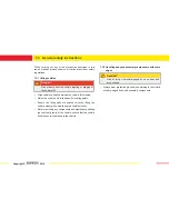
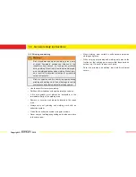
1.3.8 Working with the air conditioning system 

Warning! 

Risk of injury from the charged air conditioning system 
exploding during welding work. 

Do not weld, solder or work with a hot air gun in the vicinity of 
the components of a charged air conditioning system. Similarly, 
do not perform any welding work on a vehicle if the work will 
cause parts of the air conditioning system to heat up. 

When carrying out a paint repair, object temperatures in the 
drying oven or preheating zone must not exceed 80 °C as 
the overpressure caused by heating process may cause the 
system to explode. 

Copyright © 

2010 

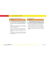
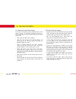
1.3.9 Handling the airbag system 

Caution! 

Risk of injury from activation of airbag units if earth 
strap is not disconnected. 

Disconnect the battery earth strap when carrying out any vehicle 
body repair work and when working on the airbag system. 

Wash hands thoroughly after touching airbag units that have 
been fired. 

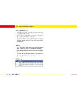
1.3.10 Working with tools 

Warning! 

Risk of injury. All tools pose potential hazards to health 
and life. Always observe the safety instructions and 
warnings of the tool manufacturers. 

Summary of Contents for 458 Italia

Page 1: ......

Page 2: ...d and certified skilled personnel Only genuine parts should be used when carrying out the repair They have been tested by Ferrari and are compatible for use with aluminium Follow the procedures exactly as given in the repair manual Any deviations from the procedures are permitted only after consultation with and approval by Ferrari Using non approved repair methods may compromise the crash performa...

Page 3: ...ength steel reinforcements A installed in the two A pillars offer occupants greater safety in critical situations A Theultra strongextrudedsectionsoftheA pillarsareconcealed below the steel reinforcements The sections are joined to the extruded members of the sill B by die cast node joints The sill B of the Ferrari F458 Italia is oversized as on a B cabriolet type vehicle This means that the Ferra...

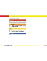
Page 4: ...that may result in death or serious injury Warning Warning indicates potential hazards that may result in death or serious injury Caution Caution indicates potential hazards that may result in slight injury This symbol also indicates hazards to property NOTE Note indicates important information Copyright 2010 ...

Page 5: ...hicle toppling or slipping off the vehicle lift Align vehicle centrally between the vehicle lift columns Raise the vehicle only at the specific locating points Ensure the lifting pads are seated correctly lifting the vehicle slowly while monitoring the vehicle visually Before removing any components and significantly shifting the centre of gravity of the vehicle ensure that the vehicle itself is sec...

Page 6: ... must be earthed and suitable powder extinguishers must be provided Any vehicle parts in the repair area which may be damaged by dust should be removed from the area or covered with fire resistant covers Copyright 2010 1 3 4 Handling batteries Warning Risk of explosion and fire from flying sparks during grinding and welding work Risk of damage to vehicle components and other vehicles from flying spark...

Page 7: ...isk of damage to vehicle components and other vehicles from flying sparks When carrying out grinding and welding work around the fuel tank or fuel carrying parts ensure that these parts do not heat up If in doubt remove such parts Cover the grinding and welding area with fire resistant covers Use the specific visor when welding Partition off workstations with spark protection curtains A fire extinguis...

Page 8: ... and fresh air ventilation Copyright 2010 1 3 7 Handling chemicals Caution Handling chemicals may cause allergic skin and respiratory tract reactions Always ensure that there is sufficient air extraction and ventilation and extract any vapours released by adhesives Prevent chemicals from coming into direct contact with the eyes and skin Wear protective gloves protective goggles and where necessary ...

Page 9: ... temperatures in the drying oven or preheating zone must not exceed 80 C as the overpressure caused by heating process may cause the system to explode Copyright 2010 1 3 9 Handling the airbag system Caution Risk of injury from activation of airbag units if earth strap is not disconnected Disconnect the battery earth strap when carrying out any vehicle body repair work and when working on the airba...

Page 10: ...ustomer following a repair test drive the vehicle carefully to ensure that it is roadworthy Repair work on the Ferrari F458 Italia must only be carried out by repair personnel who have been trained tested and certified by the Ferrari Customer Service department Use only Ferrari approved tools spare parts and consumables for repair and maintenance work If in the course of the repair work special ca...

Page 11: ...mbly are described in the Ferrari F458 Italia bodywork repair manual 1 4 4 Cuts Cuts must only be made as described by the instructions given in the Ferrari F458 Italia bodywork repair manual Load bearing components must only be parted at the original joint Cuts may only be made in the outer skin as described by the repair instructions given in this manual 1 4 5 Sanding NOTE When grinding weld sea...

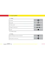
Page 12: ...elding SG tack weld SG plug weld SG continuous weld SG staggered continuous weld Spot weld SG shield gas welding 1 5 2 Riveting Solid and self piercing rivet with countersunk head Blind rivet with countersunk head Copyright 2010 ...

Page 13: ...or piercing spot welds Mill off spot weld Drill out or pierce 1 5 4 Gluing and sealing Bicomponent sealant mastic Area to be sealed with mastic 1 5 5 Cavity preservation 1 5 5 Screw symbol 1 5 5 Cutting and grinding points for weld seams Copyright 2010 ...

Page 14: ...oof Windscreen 3 Side window Roof Clearance 4 0 mm 1 0 mm Clearance Offset 2 0 mm 1 0 mm 1 5 mm Offset 8 5 mm 1 5 mm 2 Roof Windscreen 4 Roof Fender Clearance 4 0 mm 2 0 mm Clearance Minimum point 3 0 mm variable 1 5 mm Offset variable Offset ...

Page 15: ...d Bumper Clearance 3 5 mm 0 5 mm Offset 1 0 mm 1 0 mm 6 Fender Bumper grille Clearance 0 0 mm 0 5 mm Offset 0 0 mm 0 5 mm 7 Headlight Fender Clearance 3 0 mm 1 0 mm Offset 0 7 mm 0 7 mm 8 Headlight Bumper Clearance 3 0 mm 1 0 mm Offset variable ...

Page 16: ...mper Headlight Grille 11 Fender Lid Clearance 3 0 mm 1 0 mm Clearance 3 5 mm 0 5 mm Offset Offset 0 7 mm 0 7 mm 1 0 mm 10 Headlight Lid 12 Roof seal Front window surround Clearance 3 5 mm 0 5 mm Clearance 5 5 mm 1 5 mm Offset 1 4 mm 1 0 mm Offset ...

Page 17: ...ill trim panel Clearance 4 0 mm 0 7 mm Offset 0 5 mm 0 5 mm 14 Door panel Fender Clearance 3 5 mm 0 5 mm Offset 0 5 mm 0 5 mm 15 Side door Sill trim panel Clearance 4 0 mm 1 5 mm Offset 0 0 mm 1 0 mm 16 Moulding Door window Clearance Offset 8 5 mm 1 5 mm ...

Page 18: ...erlight Door window Clearance Clearance 6 3 mm 2 0 mm Offset 1 0 mm 1 0 mm Offset Var 0 8 0 7 mm 1 0 mm 18 Door panel Flank 20 Quarterlight seal Door window scraper seal Clearance 3 5 mm 0 5 mm Clearance 2 5 mm 0 5 mm Offset 0 75 mm 0 0 mm 0 75 mm Offset 0 0 mm 1 0 mm ...

Page 19: ...rance 3 5 mm 0 5 mm Offset 1 0 mm 1 0 mm 22 Rear window Air intake surround Clearance 3 0 mm 1 0 mm Offset 0 0 mm 1 0 mm 23 Roof Rear window Clearance 4 5 mm 1 0 mm Offset 1 0 mm 0 0 mm 24 Rear window Engine compartment lid Clearance 4 0 mm 1 0 mm Offset 2 0 mm 2 0 mm 1 0 mm ...

Page 20: ...ent lid Rear bumper 27 Taillight Rear bumper Clearance 4 0 mm 1 0 mm Clearance Var from 2 7 mm to 3 8 mm 1 0 mm Offset 0 0 mm 1 0 mm Offset 26 Taillight Exterior flank 28 Air intake grilles Rear bumper Clearance 3 0 mm 1 0 mm Clearance 0 0 mm 0 5 mm Offset Offset ...

Page 21: ...ir intake Rear bumper Clearance 1 0 mm 0 5 mm Offset 30 Lower air intake Diffuser Clearance 2 0 mm 0 7 mm Offset 0 0 mm 0 5 mm 31 Lower air intake Diffuser Clearance 2 0 mm 1 0 mm Offset 32 Air intake surround Exterior flank Clearance 4 0 mm 1 5 mm Offset ...

Page 22: ...ow Exterior flank Clearance 4 0 mm 1 5 mm Offset 35 Exterior flank Rear bumper Clearance 0 0 mm 0 5 mm Offset 0 0 mm 0 5 mm 34 Engine compartment lid Rear bumper Clearance 4 0 mm 1 5 mm Offset Var from 4 2 mm to 0 0 mm 1 5 mm Copyright 2010 ...

Page 23: ...ools has been developed for repairing the Ferrari F458 Italia To ensure precise fit and dimensional accuracy it is generally advised to use the set of straightening tools when carrying out all work on the vehicle structure Before separating individual parts from the body assembly When aligning and tack welding new components When welding in new components During the cooling phase after welding Copy...

Page 24: ...1 7 Car Bench vehicle bench Copyright 2010 ...

Page 25: ...1 7 Car Bench vehicle bench Copyright 2010 ...

Page 26: ...1 7 Car Bench vehicle bench Copyright 2010 ...

Page 27: ...1 7 Car Bench vehicle bench Copyright 2010 ...

Page 28: ...1 7 Car Bench vehicle bench Copyright 2010 ...

Page 29: ...1 7 Car Bench vehicle bench Copyright 2010 ...

Page 30: ...1 7 Car Bench vehicle bench Copyright 2010 ...

Page 31: ...1 7 Car Bench vehicle bench Copyright 2010 ...

Page 32: ...ates the individual box section cavities However as the bodywork may not be heated to this extent during a repair different procedures have been established for different cases Bicomponent expanded foam sealant The cavities are filled with a bicomponent foam sealant The foam sealant must form a closed cell seal The closed cell seal prevents moisture from penetrating the area concerned Foam sealant ...

Page 33: ...ary for carrying out repairs on the aluminium bodywork of the Ferrari F458 Italia If the workstation is not situated in its own dedicated enclosed space adjacent workstations used for conventional steel vehicles must be screened off with a sliding protective curtain Copyright 2010 ...

Page 34: ...mes extraction system Welding spot milling cutter Aluminium panel beating system Oxyacetylene welding equipment Riveting tongs for self piercing rivets Riveting tongs for blind rivets Pneumatic riveting tongs for blind rivets Electric body saw long stroke Pneumatic body saw short stroke Copyright 2010 Saw blades coarse tooth Hot air fan Angle grinder Cutting disc Grinding discs Hole punching plier...

Page 35: ...pairs Special tools Anew template and punch kit p n 95978256 is used for repairs in the wheelhouse area These tongs enable the removal and replacement of rivet joints at the flange connecting the two halves of the wheel housing Copyright 2010 ...

Page 36: ...passivating oxide layer is formed on its surface that protects the material underneath from environmental factors Consequently an unpainted aluminium component will not normally corrode However if aluminium comes into contact with another metal that is higher in the electromotive series than itself and an electrolyte is present at this point contact corrosion will occur Electromotive series Zinc Z...

Page 37: ...ane based permanently elastic body sealing compound and 1 component polymer based permanently elastic body sealing compound Corrosion protection treatment for the underbody Post treatment of cavities with cavity protection agents Copyright 2010 1 11 3 Screw connections Caution Bolts must not be reused Friction produced during tightening reduces the thickness of the coating Mechanical components an...

Page 38: ... been specifically designed for use with prefabricated assemblies All welding work carried out on the Space Frame assembly must be done in conjunction with a straightening system The components to be replaced must be mounted on a straightening jig Essentially this construction consists of extruded sections die cast joints cast parts gussets reinforcements The reinforcements in the A pillars are mad...

Page 39: ...ie cast node joints castings may not be repaired and must be replaced Welding of cracks is not permitted The die cast joints castings constitute the key areas of the Space Frame construction They constitute the entire welded joint area for all extruded sections The die cast joints are also used as mounts for the axle components and the engine and transmission assembly Copyright 2010 1 11 8 Gussets...

Page 40: ...458 Italia A these requirements have been met by joining the components using non thermal procedures and coated self piercing rivets Self piercing riveting is a proven joining technology for joining aluminium parts with other aluminium parts and for joining steel and aluminium parts Any heat subsequently applied to these reinforcements for example when cutting or welding results in considerable lo...

Page 41: ...4 Contains petroleum distillates hylol ethyl benzene Mixing tube for structural adhesive Wieländer Schill 838115 Silicate abrasive paper Wieländer Schill 667212 Contains silicate Aluminium filler with curing agent Wieländer Schill 542050 Polyester based aluminium filler with aluminium powder Crack testing material Cleaner Penetrating dye Developer Wieländer Schill 311051 311050 311052 Bicomponent fil...

Page 42: ...me Butyl tape Manufacturer Henkel Teroson Product number Specification Permanently elastic sealant 8 mm Single component primer Henkel Teroson Cleaner for painted areas Henkel Teroson Silicone remover Henkel Teroson Copyright 2010 ...

Page 43: ...ime saved in terms of preparation is not even remotely comparable to the amount of time wasted in having to redo a weld The following procedures are necessary The weld points on all parts of the bodywork must be ground removing the paint Before welding remove the layer of oxide with a stainless steel wire brush Before welding clean the welding area with a degreasing detergent or acetone NOTE Failu...

Page 44: ... a result of the rapid temperature change the aluminium panel shrinks at the area concerned and resumes its original shape The surrounding colder material confines the heated area and stretches less During subsequent cooling the heated buckled aluminium panel shrinks As a general rule the repair area must be heated and cooled quickly when carrying out shrinking procedures Copyright 2010 Caution Out...

Page 45: ...at for steel panels Copyright 2010 1 15 5 Joggling Joggling is a particularly suitable method for creating a backing for welding aluminium panels This should be carried out using mechanical or pneumatic joggling tools Before making a cut allow 22 mm for an overlap To allow filler to be applied subsequently to the repair area create a 45 bevel on the upper panel and deburr 1 15 6 Same material weld ...

Page 46: ...to join aluminium with steel body components One example of where this method is used are the ultra high strength steel reinforcements which are joined to the aluminium cover plate of the A pillar The self piercing rivet is made from steel and has a special coating In repairs the original self piercing rivets are replaced with solid rivets The self piercing rivet joint is removed by Copyright 2010...

Page 47: ...ing pressure for the pneumatic riveting tongs must be 8 bar Before starting the riveting procedure ensure that the parts to be joined and the rivet head are on top of one another and that there is no gap between them Copyright 2010 Blind rivet joints are critical to the strength and torsional stiffness of the bodywork Two types of blind rivet have been approved for repairs on the Ferrari F458 Ital...

Page 48: ... around the corners of extruded sections Caution All welds must be carried out with the parts fixed in the jig to prevent the parts themselves from moving during welding which would compromise the results of the repair Only remove the jigs after checking that the weld areas have cooled Copyright 2010 1 15 10 Checking weld seams and die cast node joints Caution Before using any penetrating agents cl...

Page 49: ...e the correct length of time 3 Use a detergent to completely remove any excess penetrating agent that has not permeated into the damaged surface 4 Spray on developer and allow it to act The damaged area becomes visible Check the areas for cracks If a component reveals any cracks it must be replaced If a weld seam contains cracks it must be reworked All cracks must be ground out and re welded In th...

Page 50: ... from alloys with a higher Mg and or Si content as these additive wires increase the residual melt content in the weld pool In addition to the use of inappropriate additive materials other cause for cracks include excessively shallow craters excessively short tack welds or incorrect welding sequences resulting in high shrinking stress in the event of sheet overheating or tension Subsequent process...

Page 51: ...itself before repeating the weld Fig C After welding crack testing must be repeated Cracks in the outer skin are repaired by drilling a 2 mm diameter hole at each end of the crack to prevent it from spreading Then both the crack and the holes are welded Fig D Crack Approximately double the length of the crack D Hole Hole Copyright 2010 ...

Page 52: ...en content Other possible causes of pore formation are unstable electric arc due to irregular current irregular movement of the wire electrode or incorrect weld settings incorrect placement of welding torch insufficient inert gas quantity air infiltration nozzles that are too small or obstructed by metal splashes contaminants in the weld bead area grease oil paint dirt Penetration notches Fig E are ...

Page 53: ...ld bead This however is not the case in the event of insufficient shielding gas coverage or air infiltration In these cases larger oxide inclusions may be formed resulting in significant notching due to material separation End craters A crater forms at the end of each weld bead which must be filled Fig G To do this do not turn the welding torch off at the end if the weld bead The melting welding wire ...

Page 54: ...es improves the influx of the root Application errors consist of material separation cracks with a high penetration effect which compromise the strength of the weld itself Soot deposits In event of an excessively small torch angle or incorrect welding torch movements such as when welding forward significant soot deposits may be formed in certain conditions Fig J Other causes of this phenomenon may b...

Page 55: ...f increasing the strength of the altered area Effects of Welding Heat on AlMgSi Base Material The thermally altered area is weakened by coarse segregation with mixed hypersaturated crystals in the case of a cold hardened initial state and or by increased segregation with no correlation in the case of hot hardened initial state The only way to substantially increase strength is to temper the materi...

Page 56: ...ove sealant with a rotary wire brush Aftercarryingoutrepairwork allsealsmustbereapplied as per the original assembly To prevent leaks and wind noise the body is sealed in the factory During and after work on the vehicle body maintain the factory applied corrosion protection or reapply if necessary If repair work is required on a vehicle body the following must be observed If after straightening wo...

Page 57: ...2 1 Replacing the fender Preliminary ಶ Remove connected parts bumper headlight gravel guard procedures Replacement parts Fender A Material necessary 7 x M6 screws A Copyright 2010 ...

Page 58: ...ence Removing the old part 1 Use a 10 mm wrench to remove the 2 fastener screws joining the fender and the flank of the vehicle 2 Use a 10 mm wrench to remove the 4 fastener screws joining the fender and fender mounting 1 2 Copyright 2010 ...

Page 59: ...er 3 Use a 10 mm wrench to remove the fastener screw joining the fender and the front sill pillar Fitting the new part 4 Fit the fender aligning with the holes on the fender mounting and on the vehicle flank 3 Copyright 2010 ...

Page 60: ...ws Caution Do not reuse the screws removed previously See paragraph 1 11 3 Screw connections 6 Fasten the fender to the front sill pillar with 1 M6 screw Caution Do not reuse the screws removed previously See paragraph 1 11 3 Screw connections Fitting the new part 6 5 Copyright 2010 ...

Page 61: ...th 2 M6 screws Caution Do not reuse the screws removed previously See paragraph 1 11 3 Screw connections 7 ಶ Refit connected parts bumper headlight gravel guard ಶ Check the clearance dimensions rework if necessary Remove the fender for subsequent painting Copyright 2010 ...

Page 62: ...fender mounting assembly ಶ Remove connected parts bumper headlight hinges lid ಶ Remove the fender see chapter 2 1 ಶ Place the vehicle on the vehicle bench Front fender mounting A Reinforcement base B A B 7 structural rivets Ø 6 4 4 self piercing rivets Ø 3 9 Bicomponent sealant mastic 2010 ...

Page 63: ...epair features Warning Work with the utmost caution when welding to avoid igniting any components in the vicinity Repair sequence Removing the old part 1 Sand the weld points between the fender mounting and the front trellis 1 1 1 Copyright 2010 ...

Page 64: ...r of poisoning due to fume inhalation Risk of injury from skin or eye contact with adhesive Wear breathing protection protective gloves and safety glasses 3 Remove the 3 structural rivets joining the reinforcement base and the upper diagonal brace NOTE Retrieve all the rivets using a magnet if necessary as any remaining rivets will cause noise when the vehicle is in use 3 2 Copyright 2010 ...

Page 65: ...e all the rivets using a magnet if necessary as any remaining rivets will cause noise when the vehicle is in use 5 Remove the 4 structural rivets joining the fender mounting and the lower reinforcement base 2 on outer side of vehicle 2 on inner side of vehicle NOTE Retrieve all the rivets using a magnet if necessary as any remaining rivets will cause noise when the vehicle is in use 4 4 5 5 Copyri...

Page 66: ...ly 6 Retrieve the protective foam 7 Remove the lower mounting base and sand the welding points for joining the fender mounting and the upper diagonal brace NOTE Do not remove any other material from the upper diagonal brace 7 6 Copyright 2010 ...

Page 67: ...placing the fender mounting assembly Fitting the new part 8 Sand the new part 9 Fit the outer tower then mount the fender mounting in the jig B C ಶ Prepare the weld area see chapter 1 14 8 B C Copyright 2010 ...

Page 68: ... 15 Repair methods thoroughly 10 Weld the fender mounting to the front lateral trellis at the original weld points 11 Weld the fender mounting to the upper diagonal brace at the original weld points ಶ Apply new corrosion inhibitor to the entire repair area and then apply a primer coat 10 10 10 11 Copyright 2010 ...

Page 69: ...the upper diagonal brace with 3 structural rivets 13 13 Fasten the reinforcement base to the fender mounting with 4 self piercing rivets 2 on outer side of vehicle 2 on inner side of vehicle NOTE Insert the new self piercing rivets next to the old rivet holes 14 14 Copyright 2010 ...

Page 70: ...the fender mounting assembly 14 Fasten the reinforcement base to the fender mounting with 4 structural rivets 2 on outer side of vehicle 2 on inner side of vehicle 15 Refit the protective foam 15 15 15 Copyright 2010 ...

Page 71: ...f poisoning due to fume inhalation Risk of injury from skin or eye contact with adhesive Wear breathing protection protective gloves and safety glasses 16 17 Refit the fender see chapter 2 1 ಶ Check that the part is correctly aligned ಶ Refit the door and lid ಶ Check the clearance dimensions rework if necessary Remove the fender door and lid for subsequent painting Copyright 2010 ...

Page 72: ...placing the front lateral trellis ಶ Remove connected parts headlight gravel guard radiator radiator mounting ಶ Remove the fender see chapter 2 1 ಶ Place the vehicle on the vehicle bench Front lateral trellis A Upper outer radiator mounting bracket B C B Front link tube C A 2010 ...

Page 73: ...nd the weld points between the front trellis and the front spar NOTE Do not remove any other material from the front spars 2 Sand the weld points joining the upper outer radiator mounting bracket NOTE Do not remove any other material from the front cross member 1 1 2 2 Copyright 2010 ...

Page 74: ...ber NOTE Do not remove any other material from the front cross member 4 Sand the weld points between the trellis and the shock tower NOTE Do not remove any other material from the shock tower Caution Check that there are no cracks in the shock tower In the event of damage the part must be replaced see chapter 2 6 4 3 Copyright 2010 ...

Page 75: ...e front lateral trellis 5 Sand the weld points between the trellis and the fender mounting 6 Sand the weld points between the front link tube the front lateral trellis and the front cross member 5 5 6 6 Copyright 2010 ...

Page 76: ...d above must be performed with the assistance of another worker ಶ Prepare the weld area see chapter 1 14 8 Fitting the new part NOTE Before fitting the new part read chapter 1 15 Repair methods thoroughly 8 Weld the front trellis to the cross member at the original weld points on the internal side of the vehicle Copyright 2010 ...

Page 77: ...d the cross member 10 Weld the front trellis to the front spar at the original weld points Caution When welding the front lateral trellis there is a risk of the spar A buckling as a result of the heat To prevent this the trellis must only be welded with the front cross member mounted in the jig see chapter 2 4 9 9 10 10 A A Copyright 2010 ...

Page 78: ...l trellis 11 Fit and then weld the link tube B to the front cross member and to the front lateral trellis at the original weld points 12 Weld the front trellis to the shock tower at the original weld points 11 12 11 B Copyright 2010 ...

Page 79: ...he entire repair area and then apply a primer coat 13 14 Refit the fender see chapter 2 1 ಶ Refit the door and lid ಶ Check the clearance dimensions rework if necessary NOTE Refit connected parts after tacking the trellis into position Then weld the trellis only after checking clearances Remove the fender door and lid for subsequent painting Copyright 2010 ...

Page 80: ...he front cross member ಶ Remove connected parts bumper headlights radiator tub ಶ Remove the fender see chapter 2 1 ಶ Place the vehicle on the vehicle bench Front cross member A Upper outer radiator mounting bracket B 12 structural rivets Ø 6 4 18 x M8 screws A B Copyright 2010 ...

Page 81: ...ving the old part 1 Usea13mmwrenchtoremovethe12screwslocated on the internal side of the car in correspondence with the bumper mounting brackets 2 Use a 13 mm wrench to remove the 6 screws in correspondence with the tow hook mounting 1 2 2 2 2 Copyright 2010 ...

Page 82: ...ars NOTE Do not remove any other material from the front spars 4 Remove the 12 structural rivets 6 per side connecting the front cross member and the front spars NOTE Retrieve all the rivets using a magnet if necessary as any remaining rivets will cause noise when the vehicle is in use 3 3 4 3 Copyright 2010 ...

Page 83: ...e front spars Caution Work with the utmost caution taking care not to damage the front spars 6 Mount the front cross member in the jig NOTE Check that the cross member is perfectly horizontal Prepare the weld area see chapter 1 14 ಶ Fitting the new part 5 5 Copyright 2010 ...

Page 84: ... 15 Repair methods thoroughly 7 Fit 4 structural rivets 2 per side to fix the front cross member in position NOTE Check that the cross member is flush with the front spars on both sides 8 Then fit the remaining 8 rivets 4 per side in correspondence with the holes in the front cross member 7 8 Copyright 2010 ...

Page 85: ...cing the front cross member 9 Weld the front cross member to the spars external internal lateral and upper lower at the original weld points 9 9 9 10 Fit the front lateral trellis see chapter 2 3 Copyright 2010 ...

Page 86: ... Do not reuse the screws removed previously See paragraph 1 11 3 Screw connections 11 Weld the two upper outer radiator mounting brackets to the cross member and to the front lateral trellis at the original weld points Apply new corrosion inhibitor to the entire repair area and then apply a primer coat ಶ 11 11 12 Copyright 2010 ...

Page 87: ...ot reuse the screws removed previously See paragraph 1 11 3 Screw connections 13 13 13 13 14 Refit the RH LH front trellises see chapter 2 3 15 Refit the fender see chapter 2 1 ಶ Refit the bumper and lid ಶ Check the clearance dimensions rework if necessary Remove the fender bumper and lid for subsequent painting Copyright 2010 ...

Page 88: ...the fender see chapter 2 1 ಶ Remove the front trellis see chapter 2 3 ಶ Remove the front cross member see chapter 2 4 ಶ Place the vehicle on the vehicle bench Replacement parts Front spar A Reinforcement mounting B Material necessary 10 structural rivets Ø 4 8 5 for RH spar 5 for LH spar 2 4 x M8 screws A B Copyright 2010 ...

Page 89: ... the front spar Repair sequence Removing the old part 1 Use a 13 mm wrench to remove the screws located on the internal side of the car fastening the rear luggage tub bracket 2 Cut the front spar 2 1 Copyright 2010 ...

Page 90: ...inforcement mounting NOTE Retrieve all the rivets using a magnet if necessary as any remaining rivets will cause noise when the vehicle is in use 4 Sand the lower weld points between the front spar and the reinforcement mounting NOTE Do not remove any other material from the front spars 4 3 Copyright 2010 ...

Page 91: ... NOTE Do not remove any other material from the front spars Caution Check that there are no cracks in the shock tower If any cracks are found the part must be replaced see chapter 2 6 6 Grind all the welds between the front spar and the shock tower Caution When grinding the welds take care not to damage the casting joints 5 6 Copyright 2010 ...

Page 92: ...relative recess on the shock tower NOTE Check that the front spar is perfectly horizontal ಶ Prepare the weld area see chapter 1 14 8 Check that the height of the top surface of the spar at both the inner and outer vehicle points is exactly 689 5 mm Copyright 2010 689 5 mm 689 5 mm ...

Page 93: ...nt cross member A in the jig ensuring that it is fitted correctly onto the two spars B A B 10 Fitting the new part NOTE Before fitting the new part read chapter 1 15 Repair methods thoroughly 10 Tack the front spar to the shock tower Copyright 2010 ...

Page 94: ... Perform all the welds described as follows with the part still in the jig Remove the jig only once the weld areas are cool 12 Remount the front cross member in the jig then weld the spar to the shock tower at the original weld points Apply new corrosion inhibitor to the weld beads at the lower area of the spar ಶ 12 Copyright 2010 ...

Page 95: ...5 Replacing the front spar 13 Weld the reinforcement mounting to the shock tower at the original weld points 14 Fasten the reinforcement mounting to the spar with 5 structural rivets 13 14 Copyright 2010 ...

Page 96: ... at the original weld points Apply new corrosion inhibitor to the entire repair area and then apply a primer coat ಶ 16 Fasten the rear luggage tub bracket with 2 M8 screws Caution Do not reuse the screws removed previously See paragraph 1 11 3 Screw connections 15 16 Copyright 2010 ...

Page 97: ...par to the cross member with 6 structural rivets Ø 6 4 18 Refit the front cross member see chapter 2 4 19 Refit the front trellis see chapter 2 3 20 Refit the fender mounting see chapter 2 2 ಶ Refit the fender bumper and lid ಶ Check the clearance dimensions rework if necessary Remove the fender bumper and lid for subsequent painting 17 Copyright 2010 ...

Page 98: ... Preliminary ಶ Remove connected parts dashboard interior procedures ಶ Place the vehicle on the vehicle bench Replacement parts Wheel bay cover plate A Material necessary 11 structural rivets Ø 4 8 Bicomponent sealant mastic Copyright 2010 A ...

Page 99: ...of poisoning due to fume inhalation Risk of injury from skin or eye contact with adhesive Wear breathing protection protective gloves and safety glasses 2 Remove the 4 structural rivets from the upper part of the wheel bay cover plate NOTE Retrieve all the rivets using a magnet if necessary as any remaining rivets will cause noise when the vehicle is in use 2 1 1 1 1 2 Copyright 2010 ...

Page 100: ...vets from the lower part of the wheel bay cover plate NOTE Retrieve all the rivets using a magnet if necessary as any remaining rivets will cause noise when the vehicle is in use 4 Sand the internal weld seams around the wheel bay cover plate 3 3 4 4 4 4 Copyright 2010 ...

Page 101: ...with the rivet holes on the upper diagonal brace and on the torque box ಶ Prepare the weld area see chapter 1 14 5 6 6 6 6 Fitting the new part NOTE Before fitting the new part read chapter 1 15 Repair methods thoroughly 6 Fasten the wheel bay cover plate in position with 11 structural rivets Ø 4 8 Copyright 2010 ...

Page 102: ... to the entire repair area and then apply a primer coat 8 Apply new beads of sealant mastic in all areas where it was removed previously Danger Danger of poisoning due to fume inhalation Risk of injury from skin or eye contact with adhesive Wear breathing protection protective gloves and safety glasses Refit connected parts ಶ 7 7 7 7 8 8 8 8 Copyright 2010 ...

Page 103: ...ral trellis see chapter 2 3 ಶ Remove the front cross member see chapter 2 4 ಶ Remove the front spar see chapter 2 5 ಶ Remove the roof skin see chapter 3 3 ಶ Remove the wheel bay cover plate see chapter 2 6 ಶ Place the vehicle on the vehicle bench Shock tower A Wheel bay cover plate B A Underwindscreen covering C p n 81302100 RH p n 81406900 LH 6 8 x M8 screws B 2 self piercing rivets Ø 4 8 3x2 sel...

Page 104: ...hock tower Repair sequence Removing the old part 1 Remove the 4 M8 perforating screws fastening the casting link cross member 2 Remove the 2 4 M8 screws fastening the lower front suspension cross member 1 2 Copyright 2010 ...

Page 105: ... from skin or eye contact with adhesive Wear breathing protection protective gloves and safety glasses 4 Remove the beads of sealant mastic on the 3 structural rivets connecting the torque box with the shock tower Danger Danger of poisoning due to fume inhalation Risk of injury from skin or eye contact with adhesive Wear breathing protection protective gloves and safety glasses 3 4 Copyright 2010 ...

Page 106: ...injury from skin or eye contact with adhesive Wear breathing protection protective gloves and safety glasses 5 6 6 Removing the 6 Remove the beads of sealant mastic around the underwindscreen underwindscreen covering covering Danger Danger of poisoning due to fume inhalation Risk of injury from skin or eye contact with adhesive Wear breathing protection protective gloves and safety glasses Copyrig...

Page 107: ...NOTE Do not remove any other material from the upper diagonal brace 8 Use the AVDEL FPM 35 gun to remove the 2 self piercing fastener rivets Ø 4 8 joining the underwindscreen covering and the vehicle flank NOTE Retrieve all the rivets using a magnet if necessary as any remaining rivets will cause noise when the vehicle is in use 7 7 8 Copyright 2010 ...

Page 108: ...bers and reinforcements Caution When making separating cuts take the utmost care not to damage the casting joints Check the location of any internal cross member reinforcement on the new part in order to cut correctly 10 Sand the internal lateral weld points connecting the shock tower and the front firewall Copyright 2010 9 9 9 9 10 ...

Page 109: ...ock tower and the front cross member Caution Check carefully to ensure that there is no evident buckling in the floorpan and in the reinforcements connected to the centre tunnel 12 Sand the external lateral weld points connecting the shock tower and the front firewall 11 12 Copyright 2010 ...

Page 110: ...r NOTE Retrieve all the rivets using a magnet if necessary as any remaining rivets will cause noise when the vehicle is in use 14 Sand the weld points at the ends of the windscreen valence connecting the part with the shock towers NOTE Do not remove any other material from the upper diagonal brace 13 14 Copyright 2010 ...

Page 111: ... diagonal brace to the shock tower NOTE Retrieve all the rivets using a magnet if necessary as any remaining rivets will cause noise when the vehicle is in use 16 Grind the joint welds between the upper diagonal brace and the shock tower NOTE Do not remove any other material from the upper diagonal brace 15 15 16 16 Copyright 2010 ...

Page 112: ...Do not remove any other material from the upper diagonal brace connected to the tunnel 18 Remove the 5 structural rivets 3 lateral rivets and 2 lower rivets fastening the torque box to the shock tower NOTE Retrieve all the rivets using a magnet if necessary as any remaining rivets will cause noise when the vehicle is in use 17 18 18 Copyright 2010 ...

Page 113: ...damage the parts themselves NOTE Do not remove any other material from the torque box 20 Remove the 2 structural rivets on the lower surface of the lower front suspension cross member NOTE Retrieve all the rivets using a magnet if necessary as any remaining rivets will cause noise when the vehicle is in use 19 20 Copyright 2010 ...

Page 114: ...n the lower front suspension cross member and the shock tower NOTE Do not remove any other material from the lower front suspension cross member Fitting the new part 22 Mount the shock tower in the jig and tack ಶ Prepare the weld area see chapter 1 14 21 21 Copyright 2010 ...

Page 115: ... NOTE Before fitting the new part read chapter 1 15 Repair methods thoroughly 23 Fasten the shock tower to the torque box with 5 structural rivets 24 Fasten the shock tower to the upper diagonal brace with 4 structural rivets 23 23 24 24 Copyright 2010 ...

Page 116: ...ng the shock tower 25 Fasten the shock tower to the windscreen valence with 3 structural rivets 26 Fasten the lower front suspension cross member to the shock tower with 2 structural rivets 25 25 26 Copyright 2010 ...

Page 117: ...part still in the jig Remove the jig only once the weld areas are cool 27 Weld the shock tower to the torque box and to the front cross member at the original weld points in the underbody 28 Weld the shock tower to the upper diagonal brace at the original weld points 27 28 28 Copyright 2010 ...

Page 118: ...ktowertothefrontcross memberatthe original weld points in the passenger compartment interior 30 Weld the shock tower to windscreen valence at the original weld points ಶ Apply new corrosion inhibitor to the entire repair area 29 30 Copyright 2010 ...

Page 119: ...tower 31 Weld the upper diagonal brace connected to the tunnel to the shock tower at the original weld points 32 Weld the lower front suspension cross member to the shock tower at the original weld points 31 32 Copyright 2010 ...

Page 120: ...eplacing the shock tower 33 Weld the shock tower to the front firewall at the original weld points passenger compartment interior exterior 34 Fit the wheel bay cover plate see chapter 2 6 33 33 Copyright 2010 ...

Page 121: ...4 M8 screws Caution Do not reuse the screws removed previously See paragraph 1 11 3 Screw connections 36 Fasten the casting link cross member to the shock tower with 4 M8 screws Caution Do not reuse the screws removed previously See paragraph 1 11 3 Screw connections 36 35 Copyright 2010 ...

Page 122: ... covering underwindscreen covering to the vehicle flank NOTE Insert the new self piercing rivets next to the old rivet holes 38 Weld the underwindscreen covering to the upper diagonal brace and to the A pillar flange at the original weld points ಶ Apply new corrosion inhibitor to the entire repair area and then apply a primer coat 38 38 37 Copyright 2010 ...

Page 123: ...of injury from skin or eye contact with adhesive Wear breathing protection protective gloves and safety glasses 40 Reapply all the beads of mastic sealant removed previously Danger Danger of poisoning due to fume inhalation Risk of injury from skin or eye contact with adhesive Wear breathing protection protective gloves and safety glasses 39 39 40 40 40 Copyright 2010 ...

Page 124: ... Refit the front cross member see chapter 2 4 44 Refit the front lateral trellis see chapter 2 3 45 Refit the fender mounting see chapter 2 2 46 Refit the fender see chapter 2 1 ಶ Refit connected parts ಶ Check the clearance dimensions rework if necessary Remove connected parts for subsequent painting Copyright 2010 ...

Page 125: ... the roof skin see chapter 3 3 ಶ Remove the windscreen support rib see chapter 3 4 ಶ Remove the wheel bay cover plate see chapter 2 6 ಶ Place the vehicle on the vehicle bench Front end module A Front firewall B E A B F Lower diagonal braces C Upper diagonal braces D Underwindscreen covering E Wheel bay cover plate F D Bumper mounting bracket G Casting link cross member H C 4 x M8 screws 2 self pier...

Page 126: ... end module Repair sequence Removing the old part 1 Remove the shock towers see chapter 2 7 2 Cut the 3 lower diagonal braces near the welds on the centre tunnel and on the lower front suspension cross member 2 Copyright 2010 ...

Page 127: ...near the welds on the centre tunnel 4 Grind the welds between the diagonal braces and the centre tunnel Caution Carefully check that the centre tunnel is free of cracks Caution Take the utmost care not to damage the casting joints on the centre tunnel 3 4 Copyright 2010 ...

Page 128: ...due to fume inhalation Risk of injury from skin or eye contact with adhesive Wear breathing protection protective gloves and safety glasses 6 Cut the front firewall following the floorpan centre tunnel weld line Caution When cutting the front firewall take the utmost care not to damage the casting joints on the centre tunnel 5 6 Copyright 2010 ...

Page 129: ...that there is no evident buckling on the reinforcements connected to the centre tunnel 7 Fitting the new part 8 Mount the front end module in the jig see the jigs used for the shock tower chapter 2 7 Warning This operation must be carried out with the assistance of another worker as there is a risk of crushing in the event of the front module falling ಶ Prepare the weld area see chapter 1 14 Copyri...

Page 130: ...ce and to the torque box see chapter 2 7 Caution Perform all the welds described as follows with the part still in the jig Remove the jig only once the weld areas are cool 10 Tack and then weld the three lower diagonal braces to the centre tunnel and to the lower front suspension cross member at the original weld points Fitting the new part 9 9 9 10 Copyright 2010 ...

Page 131: ... Tack and then weld the two upper diagonal braces to the centre tunnel and to the two shock towers at the original weld points 12 Weld and rivet the two shock towers at the original weld points see chapter 2 7 11 12 12 12 12 Copyright 2010 ...

Page 132: ... the front firewall in the relative recess holding it against the windscreen valence cross member A 14 Weld the front firewall to the two shock towers passenger compartment interior exterior at the original weld points A 13 14 14 Copyright 2010 ...

Page 133: ...front firewall to the front cross member and to the centre tunnel at the original weld points 16 Weld the front firewall to the windscreen valence cross member passenger compartment interior exterior at to the original weld points 15 16 Copyright 2010 ...

Page 134: ...not reuse the screws removed previously See paragraph 1 11 3 Screw connections Apply new corrosion inhibitor to the entire repair area and then apply a primer coat 18 Fit the underwindscreen covering see chapter 2 7 Replacing the shock tower step 37 19 Fit the wheel bay cover plate see chapter 2 6 ಶ 36 18 19 Copyright 2010 ...

Page 135: ...ue to fume inhalation Risk of injury from skin or eye contact with adhesive Wear breathing protection protective gloves and safety glasses 21 Reapplythebeadsofsealantmasticintheunderbody area see chapter 2 7 Danger Danger of poisoning due to fume inhalation Risk of injury from skin or eye contact with adhesive Wear breathing protection protective gloves and safety glasses 20 21 Copyright 2010 ...

Page 136: ...efit the roof skin see chapter 3 3 24 Refit the front lateral trellis see chapter 2 3 25 Refit the fender mounting see chapter 2 2 26 Refit the fender see chapter 2 1 ಶ Refit connected parts ಶ Check clearances and rectify if necessary Remove connected parts for subsequent painting Copyright 2010 ...

Page 137: ...t lid and relative hinges rear lid and relative hinges ಶ Remove the fender see chapter 2 1 ಶ Remove the fender mounting see chapter 2 2 ಶ Place the vehicle on the vehicle bench Roof skin A 8 x M6 screws 32 self piercing rivets Ø 4 8x7 5 p n 81126900 25 self piercing rivets Ø 3 9x7 0 4 self piercing rivets Ø 3 9x5 5 Bicomponent sealant mastic Expanded foam A Copyright 2010 ...

Page 138: ...halation Risk of injury from skin or eye contact with adhesive Wear breathing protection protective gloves and safety glasses 2 Sand the sections of weld in correspondence with windscreen valence cross member passenger compartment interior exterior Caution Take care not to damage the casting joints on the shock towers Repair sequence 1 1 1 1 2 2 Copyright 2010 ...

Page 139: ... on the A pillars Caution Take the utmost care not to damage the casting joints on the front sill pillar 4 Sand the weld points on the C pillars Caution Take the utmost care not to damage the casting joints on the rear sill pillar 3 3 4 Copyright 2010 ...

Page 140: ...he rivets using a magnet if necessary as any remaining rivets will cause noise when the vehicle is in use 6 Remove all the rivets in the upper windscreen area NOTE Retrieve all the rivets using a magnet if necessary as any remaining rivets will cause noise when the vehicle is in use 5 6 Copyright 2010 ...

Page 141: ...ts using a magnet if necessary as any remaining rivets will cause noise when the vehicle is in use 8 Remove all the fastener rivets joining the roof skin and the vehicle flank in the upper door area NOTE High strength self piercing rivets are used for the high strength steel reinforcements of the A pillars NOTE Retrieve all the rivets using a magnet if necessary as any remaining rivets will cause n...

Page 142: ...nector fin joining the upper skin and the vehicle flank 10 Remove all the rivets on the rear connector fin joining the upper skin and the vehicle flank NOTE Retrieve all the rivets using a magnet if necessary as any remaining rivets will cause noise when the vehicle is in use 9 10 10 Copyright 2010 ...

Page 143: ... part of the rain gutter Danger Danger of poisoning due to fume inhalation Risk of injury from skin or eye contact with adhesive Wear breathing protection protective gloves and safety glasses 12 Sand the weld points in the lower part of the rain gutter 11 12 Copyright 2010 ...

Page 144: ...kin Danger Danger of poisoning due to fume inhalation Risk of injury from skin or eye contact with adhesive Wear breathing protection protective gloves and safety glasses 14 Remove the roof skin detaching the spots of foam on the skin itself in the positions indicated 13 14 14 Copyright 2010 ...

Page 145: ...rwindscreen rib joint Upper reinforcement cross members 15 Fit the new part using the recesses in the windscreen valence cross member as reference ಶ Prepare the weld area see chapter 1 14 16 Tack the edges of the roof skin to keep it in the correct position NOTE Check the diagonal braces in the windscreen frame 15 15 16 16 16 16 Copyright 2010 ...

Page 146: ...n 17 Refit the connected parts door fender lid ಶ Check clearances and rectify if necessary Remove the connected parts Fitting the new part NOTE Before fitting the new part read chapter 1 15 Repair methods thoroughly Copyright 2010 ...

Page 147: ...s next to the old rivet holes 19 Fasten the roof skin externally to the vehicle flanks using 10x2 self piercing rivets Ø 4 8x7 5 p n 81126900 Caution The high strength steel vehicle flank reinforcements in area A must only be fastened with high strength self piercing rivets NOTE Insert the new self piercing rivets next to the old rivet holes 18 19 A Copyright 2010 ...

Page 148: ...reinforcements in area A must only be fastened with high strength structural rivets NOTE Insert the new self piercing rivets next to the old rivet holes 21 Fasten the upper part of the roof skin to the upper reinforcement cross member using 11 self piercing rivets Ø 3 9x7 NOTE Insert the new self piercing rivets next to the old rivet holes 20 20 A A 21 Copyright 2010 ...

Page 149: ...rew connections 23 Use the Avdel FPM 35 gun to apply 2x2 self piercing rivets Ø 3 9x5 5 fastening the roof skin to the vehicle flank in correspondence with the screws applied previously 24 Fasten the roof skin to the vehicle flank in correspondence with the rear connector fin using 2x2 self piercing rivets Ø 3 9x7 NOTE Insert the new self piercing rivets next to the old rivet holes 22 24 23 Copyright...

Page 150: ...of skin 25 Weld the roof skin to the underwindscreen rib at to the original weld points passenger compartment interior exterior 26 Weld the roof skin to the A pillars at the original weld points 25 25 26 26 Copyright 2010 ...

Page 151: ...entire repair area and then apply a primer coat 28 Reapply the beads of mastic removed previously from the windscreen adhesive bonding area Danger Danger of poisoning due to fume inhalation Risk of injury from skin or eye contact with adhesive Wear breathing protection protective gloves and safety glasses 27 29 28 28 28 Copyright 2010 ...

Page 152: ... due to fume inhalation Risk of injury from skin or eye contact with adhesive Wear breathing protection protective gloves and safety glasses 29 29 30 Refit the fender mounting see chapter 2 2 31 Refit the fender see chapter 2 1 ಶ Refit connected parts ಶ Check clearances and rectify if necessary Remove connected parts for subsequent painting Copyright 2010 ...

Page 153: ...al seals front lid and relative hinges rear lid and procedures relative hinges ಶ Remove the fender see chapter 2 1 ಶ Remove the roof skin see chapter 3 1 ಶ Place the vehicle on the vehicle bench Replacement parts Windscreen reinforcement support rib A Windscreen valence cross member B Material necessary 3x2 rivets Ø 6 4 Bicomponent sealant mastic B A Copyright 2010 ...

Page 154: ...joining the rib itself to the windscreen valence cross member Danger Danger of poisoning due to fume inhalation Risk of injury from skin or eye contact with adhesive Wear breathing protection protective gloves and safety glasses 2 Sand the internal sections of weld joining the windscreen valence cross member with the front firewall NOTE Do not remove any other material from the front firewall 1 2 Co...

Page 155: ...lence cross member 3 Sand the exterior sections of weld joining to the underwindscreen rib NOTE Do not remove any other material from the front firewall 4 Sandthesectionsofweldjoiningtheunderwindscreen rib and the windscreen valence cross member 3 4 Copyright 2010 ...

Page 156: ...screen rib and the underwindscreen covering 6 Remove the 3x2 structural rivets at the ends of the windscreen valence cross member fastening the part to the two front shock towers NOTE Retrieve all the rivets using a magnet if necessary as any remaining rivets will cause noise when the vehicle is in use 5 6 6 Copyright 2010 ...

Page 157: ... joining the windscreen valence cross member and the two front shock towers NOTE Do not remove any other material from the two shock towers Fitting the new part 8 Fit the windscreen valence cross member in the relative seats on the shock towers ಶ Prepare the weld area see chapter 1 14 7 8 Copyright 2010 ...

Page 158: ...oss member 10 Tack the underwindscreen rib to both the windscreen valence cross member and the underwindscreen covering 10 10 10 11 11 Fitting the new part NOTE Before fitting the new part read chapter 1 15 Repair methods thoroughly 11 Fasten the windscreen valence cross member to the shock towers using 3x2 structural rivets Ø 6 4 Copyright 2010 ...

Page 159: ... the windscreen valence cross member 12 Weld the windscreen valence cross member to the two front shock towers at the original weld points 13 Weldtheunderwindscreenribtotheunderwindscreen covering at the original weld points 12 13 Copyright 2010 ...

Page 160: ...rib and the windscreen valence cross member 14 Weld the underwindscreen rib to the front firewall at the original weld points 15 Weld the windscreen valence cross member to the front firewall at the original weld points 14 15 Copyright 2010 ...

Page 161: ...the original weld points ಶ Apply new corrosion inhibitor to the entire repair area and then apply a primer coat 17 Reapply the beads of mastic sealant removed previously Danger Danger of poisoning due to fume inhalation Risk of injury from skin or eye contact with adhesive Wear breathing protection protective gloves and safety glasses 16 17 Copyright 2010 ...

Page 162: ...the windscreen valence cross member 18 Refit the roof skin see chapter 3 1 19 Refit the fender see chapter 2 1 ಶ Refit connected parts ಶ Check the clearance dimensions rework if necessary Remove connected parts for subsequent painting Copyright 2010 ...

Page 163: ...hinges ಶ Remove the fender see chapter 2 1 ಶ Remove the fender mounting see chapter 2 2 ಶ Remove the roof skin see chapter 3 1 ಶ Remove the rear spoiler see chapter 4 1 ಶ Place the vehicle on the vehicle bench Complete vehicle flank A Rear diagonal brace B 5 x M8 screws 1 x M6 nut 38 self piercing rivets Ø 4 8x7 5 B 38 self piercing rivets Ø 3 9x7 0 5 self piercing rivets Ø 3 9x7 0 p n 81126700 A B...

Page 164: ...he rivets using a magnet if necessary as any remaining rivets will cause noise when the vehicle is in use 2 Using the AVDEL gun with the 45 mm C frame remove the rivets from the door surround lower area in correspondence with the sill NOTE Retrieve all the rivets using a magnet if necessary as any remaining rivets will cause noise when the vehicle is in use 2 1 1 1 1 Copyright 2010 ...

Page 165: ... the rivets using a magnet if necessary as any remaining rivets will cause noise when the vehicle is in use 4 Sand the underdoor weld points on the sill tubular element and on the A pillar flange Caution Check that the front sill pillar casting joints are free from cracks or buckling If any damage is noted replace the sill see chapter 3 5 Caution Take care not to damage the sill tubular element 4 4...

Page 166: ...anger Danger of poisoning due to fume inhalation Risk of injury from skin or eye contact with adhesive Wear breathing protection protective gloves and safety glasses 6 Sand the weld points on the upper flank connector cross members Caution Take care not to damage the upper flank connector cross members 6 6 5 5 Copyright 2010 ...

Page 167: ... remaining rivets will cause noise when the vehicle is in use 8 Remove the internal and external beads of mastic in theareasurroundingtheairintakeandtherearscreen interior exterior of passenger compartment Danger Danger of poisoning due to fume inhalation Risk of injury from skin or eye contact with adhesive Wear breathing protection protective gloves and safety glasses 8 8 7 7 7 Copyright 2010 ...

Page 168: ...he M6 nut fastening the vehicle flank to the rear screen bulkhead substructure 10 Sand the welds joining the vehicle flank with the rear screen bulkhead substructure NOTE Take care not to remove any other material from the rear screen bulkhead substructure 10 9 Copyright 2010 ...

Page 169: ...the rear screen bulkhead 12 Remove the beads of sealant mastic in correspondence with the front sill pillar Danger Danger of poisoning due to fume inhalation Risk of injury from skin or eye contact with adhesive Wear breathing protection protective gloves and safety glasses 11 11 12 Copyright 2010 ...

Page 170: ...ot to damage the die cast joints Check that the front sill pillar die cast joints are free from cracks If any damage is noted replace the sill see chapter 3 5 14 Use a 13 mm wrench to remove the 2 M8 screws from the front pillar interior of vehicle NOTE When removing the screws take the utmost care not to let them fall into the front door pillar 14 13 Copyright 2010 ...

Page 171: ...necessary as any remaining rivets will cause noise when the vehicle is in use 16 Remove the rear diagonal brace sanding the weld points at the ends Caution Check that the rear sill pillar casting joints are free from cracks or buckling If any damage is noted replace the sill see chapter 3 5 NOTE Do not remove any other material from the rear sill pillar and from the casting for the rear shock towe...

Page 172: ...cessary as any remaining rivets will cause noise when the vehicle is in use 18 Remove the beads of sealant mastic in correspondence with the rear sill pillar and the rear screen bulkhead rear lid area Danger Danger of poisoning due to fume inhalation Risk of injury from skin or eye contact with adhesive Wear breathing protection protective gloves and safety glasses 18 17 Copyright 2010 ...

Page 173: ...he die cast joints Check that the rear sill pillar die cast joints are free from cracks If any damage is noted replace the sill see chapter 3 5 20 Using the AVDEL FPM 35 gun remove the 5 self piercing rivets joining the vehicle flank with the rear trellis NOTE Retrieve all the rivets using a magnet if necessary as any remaining rivets will cause noise when the vehicle is in use 20 19 Copyright 2010...

Page 174: ...rieve all the rivets using a magnet if necessary as any remaining rivets will cause noise when the vehicle is in use 22 Use a 13 mm wrench to remove the 3 M8 fastener screws joining the vehicle flank and the rear sill pillar NOTE When removing the screws take the utmost care not to let them fall into the front door pillar 22 21 Copyright 2010 ...

Page 175: ...r eye contact with adhesive Wear breathing protection protective gloves and safety glasses 24 Sand the joint weld beads between the vehicle flank and the upper casting of the rear sill pillar interior of passenger compartment Caution Take the utmost care not to damage the die cast joints Check that the rear sill pillar die cast joints are free from cracks If any damage is noted replace the sill see...

Page 176: ... necessary adjust the gap from the sill wall to the exterior of the bracket to the correct value of 115 mm 26 Check that the rear fender mounting bracket is not damaged If necessary adjust the gap from the vertical wall of the pillar reinforcement to the correct value of 115 mm 115 mm 115 mm Copyright 2010 ...

Page 177: ...ust be carried out with the assistance of another worker as the size of the vehicle flank makes is difficult to position correctly ಶ Prepare the weld area see chapter 1 14 28 Fit the 2 M8 screws onto the front pillar Caution Do not reuse the screws removed previously See paragraph 1 11 3 Screw connections 28 Copyright 2010 ...

Page 178: ... Screw connections 30 Fit the external tower and the relative jigs to ensure that the vehicle flank is positioned correctly Fit the rear spoiler and fasten in position Check the clearance dimensions rework if necessary Remove the rear spoiler NOTE Check that the vehicle flank is correctly fitted onto the upper reinforcement cross members ಶ ಶ 29 Copyright 2010 ...

Page 179: ... Repair methods thoroughly 31 Tighten the 5 M8 screws applied previously 32 Fasten the vehicle flank to the rear screen bulkhead substructure with an M6 nut Caution Do not reuse the screws removed previously See paragraph 1 11 3 Screw connections Fitting the new part 32 31 31 Copyright 2010 ...

Page 180: ...llises with 5 self piercing rivets Ø 3 9x7 0 p n 81126700 NOTE Insert the new self piercing rivets next to the old rivet holes 34 Fasten the vehicle flank to the rear flank connector cross member with 2 self piercing rivets Ø 3 9x7 0 NOTE Insert the new self piercing rivets next to the old rivet holes 33 34 Copyright 2010 ...

Page 181: ... the new self piercing rivets next to the old rivet holes 36 Fasten the vehicle flank to the A pillar with 22 self piercing rivets Ø 4 8x7 5 Caution The high strength A pillar reinforcements must only be fastened with high strength structural rivets NOTE Insert the new self piercing rivets next to the old rivet holes 36 36 36 36 35 Copyright 2010 ...

Page 182: ...aution The high strength A pillar reinforcements must only be fastened with high strength structural rivets NOTE Insert the new self piercing rivets next to the old rivet holes 38 Fastentheflanktothelowerrearfenderreinforcement with 6 self piercing rivets Ø 3 9x7 0 NOTE Insert the new self piercing rivets next to the old rivet holes 38 37 Copyright 2010 ...

Page 183: ...cing rivets Ø 4 8x7 5 NOTE Insert the new self piercing rivets next to the old rivet holes Rivet the passenger compartment interior side first and then the passenger compartment exterior side Caution Perform all the welds described as follows with the part still in the jig Remove the jig only once the weld areas are cool 40 Weld the vehicle flank to the sill tubular element and to the A pillar flange...

Page 184: ...he front sill pillar at the original weld points 42 Insert the 4 self piercing rivets Ø 3 9x7 0 in the inner area of the rear lid in correspondence with the two brackets fastened to the rear trellis NOTE Insert the new self piercing rivets next to the old rivet holes 42 42 41 Copyright 2010 ...

Page 185: ...ehicle flank 43 Weld the vehicle flank to the upper casting of the rear sill pillar at the original weld points rear lid area 44 Fasten the rear diagonal brace by welding the ends at the original weld points 44 44 43 Copyright 2010 ...

Page 186: ... Weld the vehicle flank to the upper casting of the rear sill pillar at the original weld points passenger compartment interior 46 Weld the vehicle flank to the upper reinforcement cross members at the original weld points 46 46 45 Copyright 2010 ...

Page 187: ...rea and then apply a primer coat 48 Reapply the beads of sealant mastic in the area surrounding the air intake and the rear screen interior exterior of passenger compartment Danger Danger of poisoning due to fume inhalation Risk of injury from skin or eye contact with adhesive Wear breathing protection protective gloves and safety glasses 48 48 47 47 Copyright 2010 ...

Page 188: ...e inhalation Risk of injury from skin or eye contact with adhesive Wear breathing protection protective gloves and safety glasses 50 Reapply the beads of sealant mastic in correspondence with the upper casting of the front sill pillar Danger Danger of poisoning due to fume inhalation Risk of injury from skin or eye contact with adhesive Wear breathing protection protective gloves and safety glasse...

Page 189: ... skin or eye contact with adhesive Wear breathing protection protective gloves and safety glasses 51 51 52 Refit the roof skin see chapter 3 1 53 Refit the rear spoiler see chapter 4 1 54 Refit the fender mounting see chapter 2 2 55 Refit the fender see chapter 2 1 ಶ Refit connected parts ಶ Check clearances and rectify if necessary Remove connected parts for subsequent painting Copyright 2010 ...

Page 190: ... relative hinges rear lid and relative hinges Remove the fender see chapter 2 1 Remove the fender mounting see chapter 2 2 Remove the roof skin see chapter 3 1 Remove the complete vehicle flank see chapter 3 3 Place the vehicle on the vehicle bench Replacement parts Complete vehicle flank A Lateral crash reinforcement B Material necessary 5 x M8 screws B A Copyright 2010 ...

Page 191: ...M8 fastener screws joining the lateral crash reinforcement the rear sill pillar and the extruded elements A NOTE When removing the screws take the utmost care not to let them fall into the rear door pillar Fitting the new part 2 Fit the rear tower and mount the lateral crash reinforcement in the jig 1 A 1 1 Copyright 2010 ...

Page 192: ... the extruded elements A with 5 M8 screws Caution Do not reuse the screws removed previously See paragraph 1 11 3 Screw connections Fitting the new part 3 A 3 3 4 Refit the vehicle flank see chapter 3 3 NOTE Carry out final adjustment of the lateral crash reinforcement only after refitting the vehicle flank Copyright 2010 ...

Page 193: ...Refit the roof skin see chapter 3 1 6 Refit the fender mounting see chapter 2 2 7 Refit the fender see chapter 2 1 ಶ Refit connected parts ಶ Check the clearance dimensions rework if necessary Remove connected parts for subsequent painting Copyright 2010 ...

Page 194: ...roof skin see chapter 3 1 ಶ Remove the underwindscreen covering see chapter 2 6 Replacing the shock tower ಶ Remove the complete vehicle flank see chapter 3 3 ಶ Remove the lateral crash reinforcement see chapter 3 4 ಶ Remove the rear firewall and mountings see chapter 3 6 ಶ Place the vehicle on the vehicle bench Sill A A pillar flange B Wheel bay cover plate C Torque box only if necessary D Upper diag...

Page 195: ...Replacing the sill Material necessary 9 structural rivets Ø 4 8x9 0 31 structural rivets Ø 6 4x19 2 Repair sequence Removing the old part 1 Remove the wheel bay cover plate see chapter 2 7 1 Copyright 2010 ...

Page 196: ...kwiththeutmostcautiontopreventdamaging the internal diagonal braces connected to the centre tunnel the upper diagonal brace and the 2 2 2 torque box 2 3 Remove the structural fastener rivets joining the sill and the semi floorpan NOTE Retrieve all the rivets using a magnet if necessary as any remaining rivets will cause noise when the vehicle is in use 3 3 Copyright 2010 ...

Page 197: ...m the diagonal braces connecting to the centre tunnel 4 4 5 Remove the beads of sealant mastic in correspondence with the 3 structural fastener rivets joining the front sill pillar and the torque box Danger Danger of poisoning due to fume inhalation Risk of injury from skin or eye contact with adhesive 5 Wear breathing protection protective gloves and safety glasses Copyright 2010 ...

Page 198: ...ior exterior of passenger compartment NOTE Retrieve all the rivets using a magnet if necessary as any remaining rivets will cause noise when the vehicle is in use 7 Sand the joint weld beads between the front sill pillar and the torque box NOTE Do not remove any other material from the torque box 6 7 7 6 Copyright 2010 ...

Page 199: ...einforcement and from the torque box A 8 9 Removethebeadsofsealantmasticincorrespondence with the weld beads in the underbody between the sill the torque box and the reinforcement A Danger Danger of poisoning due to fume inhalation Risk A of injury from skin or eye contact with adhesive Wear breathing protection protective gloves and safety glasses 9 Copyright 2010 ...

Page 200: ... and the reinforcement A NOTE Do not remove any other material from the reinforcement A and from the torque box A 10 11 Sand the internal and external joint weld beads between the sill and the upper diagonal brace NOTE Do not remove any other material from the upper diagonal brace 11 Copyright 2010 11 ...

Page 201: ...bracing NOTE Retrieve all the rivets using a magnet if necessary as any remaining rivets will cause noise when the vehicle is in use 12 13 Sand the joint spot welds between the sill and the internal B pillar bracing NOTE Do not remove any other material from the sill connector cross member Copyright 2010 13 ...

Page 202: ...remove any other material from the sill connector cross member NOTE 14 The facilitate the operation described above remove the external bracing 15 Gradually sand the joint weld beads between the fuel tank cross member and the upper sill casting 15 NOTE Do not remove any other material from the fuel tank cross member 15 Copyright 2010 ...

Page 203: ...magnet if necessary as any remaining rivets will cause noise when the vehicle is in use 16 16 16 16 17 Sand the joint weld beads in the underbody between the sill the lower extruded element C and the sill connector cross member Caution Work with the utmost caution to prevent damaging the lower extruded element C 17 NOTE Do not remove any other material from the sill 17 C connector cross member 17 ...

Page 204: ...ll 18 Sand the remaining weld beads in the underbody to facilitate removal of the sill Fitting the new part 19 Fit the external tower the mount the sill in the jig ಶ Prepare the weld area see chapter 1 14 Copyright 2010 18 ...

Page 205: ...ctly into the torque box and the upper diagonal brace Check that the semi floorpan is fitted correctly Fitting the new part NOTE 20 Before fitting the new part read chapter 1 15 Repair methods thoroughly 20 Tack the sill to the torque box and to the upper 20 diagonal brace 20 Copyright 2010 ...

Page 206: ...on This operation must only be performed with the two cross members mounted in the jig NOTE Check that the upper casting of the B pillar is 21 fitted correctly into the fuel tank cross member 21 21 22 Tackthesilltotheinternaldiagonalbracesconnecting to the centre tunnel NOTE Check again that the semi floorpan is fitted correctly 22 22 Copyright 2010 ...

Page 207: ...llar to the torque box at the original weld points interior exterior of passenger compartment 24 Fasten the front sill pillar and the torque box interior exterior of passenger compartment with 6 structural rivets Ø 6 4x19 2 24 24 23 23 Copyright 2010 ...

Page 208: ...he sill 25 Weldthesilltothetorqueboxandtothereinforcement A at the original weld points in the underbody A 25 26 Weld the rear sill pillar to the fuel tank cross member at the original weld points 26 26 Copyright 2010 ...

Page 209: ...eplacing the sill 27 Weld the sill to the upper diagonal brace at the original interior and exterior weld points 28 Weld the sill to the reinforcement A at the original weld points 27 27 28 A Copyright 2010 ...

Page 210: ...e tunnel at the original weld points 29 29 30 Fasten the semi floorpan to the sill tubular element starting at the bottom and working upward with 9 structural rivets Ø 4 8x9 0 NOTE When reinstalling the electrical system apply a protective pad to prevent contact between the 30 30 cables and any protruding rivets Copyright 2010 ...

Page 211: ...s member vehicle interior exterior at the original weld points ಶ Apply new corrosion inhibitor to the entire repair area Caution 31 Remove the jigs retaining the sill only after the welds have cooled 32 Mount the lower extruded element C in the jig C Copyright 2010 31 ...

Page 212: ...ment C to the sill and to the sill connector cross member at the original weld points 33 C 33 33 33 34 Fasten the lower extruded element C to the sill and to the sill connector cross member with 8 structural rivets Ø 6 4x19 2 C 34 34 34 34 Copyright 2010 ...

Page 213: ...3 5 Replacing the sill 35 Fit the external bracing and weld to the sill ಶ Reapply corrosion inhibitor to the new weld beads 35 36 Fit the internal bracing and weld to the sill Copyright 2010 36 ...

Page 214: ...e internal and external bracing to the sill with 17 structural rivets Ø 6 4x19 2 37 37 38 Fit the front covering with the two holes D on the covering itself aligned with the two threaded holes in the front sill pillar D Copyright 2010 37 ...

Page 215: ...ith the holes in the covering itself ಶ Reapply corrosion inhibitor to the weld beads between the two bracings 40 Fit the rear covering bringing it up against the rear sill pillar NOTE Check that the rear covering is flush with the front covering fitted previously 39 39 Copyright 2010 ...

Page 216: ...e sill 41 Weld the rear covering to the sill in correspondence with the holes in the covering itself 42 Fit the front flank mounting bracket as shown in the diagram aside 129 5 mm 32 mm 26 mm 11 mm 41 41 Copyright 2010 ...

Page 217: ... sill 43 Weld the front flank mounting bracket to the sill and to the external bracing 44 Fit the A pillar flange against the front sill pillar with the notch in the flange over the lower sill pillar weld Copyright 2010 43 ...

Page 218: ...orrosion inhibitor to the entire repair area and then apply a primer coat E 45 46 Reapply the beads of mastic sealant removed previously Danger Danger of poisoning due to fume inhalation Risk of injury from skin or eye contact with adhesive Wear breathing protection protective gloves and safety glasses 46 Copyright 2010 46 ...

Page 219: ...l crash reinforcement see chapter 3 4 53 Refit the complete vehicle flank see chapter 3 3 54 Refit the rear spoiler see chapter 4 1 55 Refit the roof skin see chapter 3 1 56 Refit the underwindscreen covering see chapter 2 6 Replacing the shock tower 57 Refit the rear end module see F458 Italia workshop manual 58 Refit the fender mounting see chapter 2 2 59 Refit the fender see chapter 2 1 ಶ Refit connecte...

Page 220: ...ior trim windows lateral seals rear lid and relative hinges doors ಶ Remove the rear end module see F458 Italia workshop manual ಶ Place the vehicle on the vehicle bench Rear firewall A RH lateral firewall mounting B LH lateral firewall mounting C 16 x M6 screws 36 structural rivets Ø 4 8x10 0 6 threaded M6x21 5 rivets A C B Copyright 2010 ...

Page 221: ...ng due to fume inhalation Risk of injury from skin or eye contact with adhesive Wear breathing protection protective gloves and safety glasses 2 Remove the beads of sealant mastic on the perimeter of the rear firewall engine area Danger Danger of poisoning due to fume inhalation Risk of injury from skin or eye contact with adhesive Wear breathing protection protective gloves and safety glasses 1 2 ...

Page 222: ...ner screws joining the firewall and the rear bulkhead 4 Remove the threaded fastener rivets M6x21 5 joining the rear firewall and the fuel tank cross member NOTE Retrieve all the rivets using a magnet if necessary as any remaining rivets will cause noise when the vehicle is in use 4 3 3 3 3 Copyright 2010 ...

Page 223: ...net if necessary as any remaining rivets will cause noise when the vehicle is in use 6 Remove the structural fastener rivets joining the firewall the fuel tank cross member and the sill connector cross member NOTE Retrieve all the rivets using a magnet if necessary as any remaining rivets will cause noise when the vehicle is in use 6 6 6 5 5 Copyright 2010 ...

Page 224: ...ts using a magnet if necessary as any remaining rivets will cause noise when the vehicle is in use 8 Sand the joint weld beads between the RH and LH firewall mountings and the rear sill pillars Caution Check that the rear sill pillar casting joints are free from cracks or buckling If any damage is noted replace the sill see chapter 3 5 8 8 7 7 Copyright 2010 ...

Page 225: ...gainst the sill tubular elements and tack in position ಶ Prepare the weld area see chapter 1 14 10 Fit the rear firewall in the seat bringing it up against the relative mountings NOTE Fit the rear firewall from the passenger compartment interior side to facilitate installation of the new part 9 9 Copyright 2010 ...

Page 226: ... Before fitting the new part read chapter 1 15 Repair methods thoroughly 11 Fasten the firewall to the sill connector cross member with 16 structural rivets Ø 4 8x10 0 12 Fasten the back of the firewall engine area with 10 structural rivets Ø 4 8x10 0 11 12 12 Copyright 2010 ...

Page 227: ...ll and mountings 13 Weld the RH and LH firewall mountings to the rear sill pillars at the original weld points 14 Fasten the firewall to the relative RH and LH mountings with 2 structural rivets Ø 4 8x10 0 13 13 14 14 Copyright 2010 ...

Page 228: ...wall and mountings 15 Fasten the firewall to the fuel tank cross member with 8 structural rivets Ø 4 8x10 0 16 Fasten the firewall to the centre of the fuel tank cross member with 6 threaded rivets M6x21 5 16 15 15 Copyright 2010 ...

Page 229: ...nhibitor to the welds on the RH and LH firewall mountings and apply a coat of primer to the repair areas ಶ 18 Reapply the beads of mastic sealant on the upper portion of the rear firewall passenger compartment interior Danger Danger of poisoning due to fume inhalation Risk of injury from skin or eye contact with adhesive Wear breathing protection protective gloves and safety glasses 18 18 17 17 17 1...

Page 230: ...oisoning due to fume inhalation Risk of injury from skin or eye contact with adhesive Wear breathing protection protective gloves and safety glasses 19 19 20 Refit the rear end module see F458 Italia workshop manual ಶ Refit connected parts ಶ Check the clearance dimensions rework if necessary Remove connected parts for subsequent painting Copyright 2010 ...

Page 231: ...l seals rear lid and relative hinges ಶ Remove the rear end module see F458 Italia workshop manual ಶ Remove the rear firewall see chapter 3 6 ಶ Remove the lateral firewall mountings see chapter 3 6 ಶ Place the vehicle on the vehicle bench Fuel tank cross member A A Rear screen bulkhead substructure B Rear firewall C B Lateral firewall mountings D D 16 x M8 screws C D 2010 ...

Page 232: ...pair sequence Removing the old part 1 Use a 13 mm wrench to remove the 8 screws fastening the mountings A to the fuel tank cross member 2 Use a 13 mm wrench to remove the 8 screws fastening the internal tubular elements 2 2 1 1 A Copyright 2010 ...

Page 233: ...utmost care not to damage the die cast joints Check that the rear sill pillar die cast joints are free from cracks If any damage is noted replace the sill see chapter 3 5 4 Gradually grind the weld beads between the fuel tank cross member and the casting joints on the rear sill pillars Caution Take the utmost care not to damage the die cast joints 4 4 4 3 ...

Page 234: ...jig ಶ Prepare the weld area see chapter 1 14 Fitting the new part NOTE Before fitting the new part read chapter 1 15 Repair methods thoroughly 6 Tack the fuel tank cross member to the casting joints on the rear sill pillars NOTE Check that the fuel tank cross member is perfectly horizontal 6 Copyright 2010 ...

Page 235: ... retaining the fuel tank cross member only after the welds have cooled Apply new corrosion inhibitor to the entire repair area and then apply a primer coat ಶ 8 Fasten the mountings A to the fuel tank cross member with 8 M8 screws Caution Do not reuse the screws removed previously See paragraph 1 11 3 Screw connections 7 7 7 8 8 A Copyright 2010 ...

Page 236: ...ews removed previously See paragraph 1 11 3 Screw connections 9 9 10 Refit the lateral firewall mountings see chapter 3 6 11 Refit the rear firewall see chapter 3 6 12 Refit the rear end module F458 Italia workshop manual ಶ Refit connected parts ಶ Check clearances and rectify if necessary Remove connected parts for subsequent painting Copyright 2010 ...

Page 237: ... spoiler see chapter 4 1 ಶ Remove the roof skin see chapter 3 1 ಶ Remove the complete vehicle flank see chapter 3 3 ಶ Remove the lateral crash reinforcement see chapter 3 4 ಶ Remove the front rear lateral trellises see chapter 3 10 ಶ Place the vehicle on the vehicle bench Subframe connector extruded element A Lateral crash reinforcement tubular element B Rear mounting bracket for rear flank C Rear p...

Page 238: ...ext to the weld beads Caution Take the utmost care not to damage the casting joints on the rear sill pillar 2 Grind the joint weld beads between the lateral crash reinforcement tubular element the rear pillar reinforcement and the suspension casting reinforcement NOTE Do not remove any other material from the rear sill pillar D and the upper external diagonal brace E Repair sequence 1 2 1 2 1 2 D ...

Page 239: ...rame connector extruded element in the jig ಶ Prepare the weld area see chapter 1 14 4 Fitting the new part NOTE Before fitting the new part read chapter 1 15 Repair methods thoroughly 4 Fit the lateral crash reinforcement tubular element in the relative seat on the sill and tack Copyright 2010 ...

Page 240: ...the lateral crash reinforcement tubular element and the subframe connector extruded element and tack 6 Check that the part is correctly positioned then weld the lateral crash reinforcement tubular element to the sill and to the subframe connector extruded element at the original weld points 5 5 5 6 6 Copyright 2010 ...

Page 241: ...o the lateral crash reinforcement at the original weld points ಶ Apply new corrosion inhibitor to the entire repair area 8 Fit the suspension casting reinforcement in the seat between the two extruded elements fitted previously Tack the suspension casting reinforcement at the ends 7 7 7 7 7 8 8 8 Copyright 2010 ...

Page 242: ...t the original weld points Caution Removethejigretainingthesubframeconnector extruded element only after the welds have cooled Apply new corrosion inhibitor to the entire repair area ಶ 10 Fit the external tower then mount the flank mounting bracket A in the jig NOTE Check that the distance between the outer edge of the bracket A and the sill wall is 115 mm 9 9 A 115 mm Copyright 2010 ...

Page 243: ...lements fitted previously 12 Refit the front rear lateral trellises see chapter 3 10 13 Refit the lateral crash reinforcement see chapter 3 4 14 Refit the complete vehicle flank see chapter 3 3 15 Refit the rear spoiler see chapter 4 1 16 Refit the roof skin see chapter 3 1 17 Refit the rear end module see F458 Italia workshop manual 11 11 A Copyright 2010 ...

Page 244: ... 3 8 Replacing the subframe connector extruded section ಶ Refit connected parts ಶ Check the clearance dimensions rework if necessary Remove connected parts for subsequent painting Copyright 2010 ...

Page 245: ...ual ಶ Remove the rear spoiler see chapter 4 1 ಶ Remove the roof skin see chapter 3 1 ಶ Remove the complete vehicle flank see chapter 3 3 ಶ Remove the front rear lateral trellises see chapter 3 10 ಶ Place the vehicle on the vehicle bench Replacement parts Casting for rear shock tower A Front rear lateral trellises B Upper external diagonal brace C Material necessary 4 x M8 screws 2 structural rivets...

Page 246: ...e the utmost care not to damage the casting joints Check the location of any internal cross member reinforcement on the new part in order to cut correctly 2 Remove the 2 structural fastener rivets joining the upper external diagonal brace and the die cast sill joint NOTE Retrieve all the rivets using a magnet if necessary as any remaining rivets will cause noise when the vehicle is in use 1 2 Copy...

Page 247: ... weld between the upper external diagonal brace and the suspension casting reinforcement NOTE Do not remove any other material from the upper external diagonal brace 4 Use a 13 mm wrench to remove the 4 M8 screws fastening the internal tubular element 3 4 4 Copyright 2010 ...

Page 248: ...ads between the upper external diagonal brace and the die cast sill joint Caution Take the utmost care not to damage the die cast sill joint If the event of damage the sill must be replaced see chapter 3 5 5 5 6 Grind all the weld beads sanded previously Copyright 2010 ...

Page 249: ...apter 1 14 ಶ NOTE Before fitting the new part read chapter 1 15 Repair methods thoroughly 8 Fasten the casting for the rear shock tower to the shock tower itself with 3 M12 screws Caution Do not reuse the screws removed previously See paragraph 1 11 3 Screw connections Fitting the new part Fitting the new part 8 8 Copyright 2010 ...

Page 250: ...e against the relative seat on the die cast rear sill pillar joint and tack in position Check that the upper external diagonal brace is correctly positioned 10 Fasten the upper external diagonal brace to the die cast sill joint with 2 structural rivets Ø 6 4x19 2 9 10 Copyright 2010 ...

Page 251: ... the die cast sill joint at the original weld points 12 Weld the upper external diagonal brace to the casting for the rear shock tower at the original weld points Caution Remove the jig retaining the casting for the rear shock tower only after the welds have cooled 11 11 12 Copyright 2010 ...

Page 252: ...complete vehicle flank see chapter 3 3 15 Refit the rear spoiler see chapter 4 1 16 Refit the roof skin see chapter 3 1 17 Refit the rear end module see F458 Italia workshop manual ಶ Refit connected parts ಶ Check the clearance dimensions rework if necessary Remove connected parts for subsequent painting Copyright 2010 ...

Page 253: ...nt lid and relative hinges rear lid and relative hinges ಶ Remove the roof skin see chapter 3 3 ಶ Remove the complete vehicle flank see chapter 3 5 ಶ Place the vehicle on the vehicle bench Rear lateral trellis A Angle piece for flank mounting bracket B Central substructure mounting bracket C Central substructure mounting bracket D 1 x M8 screw 2 x M6 screws A C D B A Copyright 2010 ...

Page 254: ...medboth with the rear end module installed or removed 1 Sand the weld points on the rear trellis NOTE Do not remove any other material from the rear trellis 2 Sand the weld points between the connecting brackets and the rear trellis NOTE Do not remove any other material from the connecting brackets 1 2 Copyright 2010 ...

Page 255: ...ule installed remove the M8 screw A and the 2 M6 screws B fastening the lateral trellis to the rear subframe B A 3 Sand the weld points between the connecting brackets and the rear pillar reinforcement NOTE Do not remove any other material from the connecting brackets 3 Copyright 2010 ...

Page 256: ...rear lateral trellis Fitting the new part 4 Mount the lateral trellis in the jig ಶ Prepare the weld area see chapter 1 14 5 Fit the trellis connector in the relative seats on the rear pillar reinforcement 5 Copyright 2010 ...

Page 257: ...OTE Before fitting the new part read chapter 1 15 Repair methods thoroughly 6 Weld the lateral trellis at all the original weld points 7 Position the bracket C p n 81649700 RH p n 81649800 LH 90 mm from the edge of the extruded section D C D 90 mm 6 Copyright 2010 ...

Page 258: ...ear lateral trellis 8 Fasten the bracket C to the extruded section D with four 15 mm lengths of weld 9 Fit the rear bracket E p n 81583200 RH p n 81583300 LH centring with the seat on the bushing F C D E F 8 Copyright 2010 ...

Page 259: ...o the extruded section D with four 20 mm lengths of weld 11 Mount the bracket G p n 81952000 in the jig NOTE When working with the rear subframe module installed on the vehicle use the module itself as a template for correctly fitting the bracket G E D 10 G Copyright 2010 ...

Page 260: ...lis with two 30 mm lengths of weld and two 10 mm lengths of weld 13 Fit the bracket H p n 81582600 RH p n 81582700 LH on the rear trellis holding the bracket with the inner side flush and at a distance of 5 mm from the front end of the extruded section I H G I 5 mm 12 Copyright 2010 ...

Page 261: ...w corrosion inhibitor to the entire repair area and then apply a primer coat NOTE When working with the rear subframe module installed fasten the lateral trellis to the rear subframe with 1 M8 screw A and 2 M6 screws B Caution Do not reuse the screws removed previously See paragraph 1 11 3 Screw connections H I 14 B A Copyright 2010 ...

Page 262: ...eral trellis 15 Refit the complete vehicle flank see chapter 3 5 16 Refit the roof skin see chapter 3 3 ಶ Refit connected parts ಶ Check clearances and rectify if necessary Remove connected parts for subsequent painting Copyright 2010 ...

Page 263: ...essary 4 1 Replacing the rear spoiler ಶ Remove connected parts rear bumper taillights grilles and if necessary rear lid ಶ Place the vehicle on the vehicle bench Rear spoiler A Rear bumper mounting cross member B 2 M6x18 screws 5 M6 nuts A B Copyright 2010 ...

Page 264: ...and the joint weld beads between the rear spoiler and the vehicle flanks 1 NOTE Do not remove any other material from the vehicle flanks 2 Use a 10 mm wrench to remove the 2 M6x18 fastener screws joining the spoiler and the rear 2 bumper mounting cross member Copyright 2010 1 ...

Page 265: ...the rear spoiler 3 Use a 10 mm wrench to remove the 5 M6 fastener nuts joining the spoiler the rear bumper mounting 3 3 3 cross member and the mounting bracket 4 Clean any welding and filler residue 4 4 Copyright 2010 ...

Page 266: ...the vehicle flanks ಶ Prepare the weld area see chapter 1 14 5 Fitting the new part NOTE Before fitting the new part read chapter 1 15 Repair methods thoroughly 6 Fasten the spoiler to the rear bumper mounting cross member with the 2 M6x18 screws Caution Do not reuse the screws removed previously See paragraph 1 11 3 Screw connections Copyright 2010 6 ...

Page 267: ...ts removed previously 7 7 7 Caution Do not reuse the nuts removed previously See paragraph 1 11 3 Screw connections ಶ Refit connected parts ಶ Check clearances on the rear lid and rectify if necessary Remove the connected parts for subsequent painting Copyright 2010 ...

Page 268: ...Replacing the rear spoiler 8 Weld the rear spoiler to the vehicle flanks at the original weld points ಶ Apply new corrosion inhibitor to the entire repair area and then apply a primer coat 8 Copyright 2010 8 ...

Page 269: ...er mounting cross member Preliminary ಶ Remove connected parts bumper taillights grilles procedures ಶ Place the vehicle on the vehicle bench Replacement parts Rear bumper mounting cross member A Material necessary A Copyright 2010 ...

Page 270: ...cross member Repair sequence Removing the old part 1 Roughly cut out the rear cross member 2 Sand the joint weld beads between the cross member and the rear spars NOTE Do not remove any other material from the rear spars 1 1 2 Copyright 2010 ...

Page 271: ...tion Check that the rear spars are undamaged In the event of damage the spars must be replaced see chapter 4 3 4 Mount the rear cross member in the jig NOTE Check that the cross member is flush with the rear spars Prepare the weld area see chapter 1 14 ಶ Fitting the new part 3 4 Copyright 2010 ...

Page 272: ...member to the spars Caution Remove the jig only once the weld areas are cool Fitting the new part 5 ಶ Apply new corrosion inhibitor to the entire repair area and then apply a primer coat ಶ Refit the connected parts taillights grilles rear bumper ಶ Check clearances on the rear lid and rectify if necessary Remove connected parts for subsequent painting Copyright 2010 ...

Page 273: ...lles procedures ಶ Remove the rear upper trellis see chapter 4 4 ಶ Remove the flank mounting bracket see chapter 4 5 ಶ Remove the rear cross member see chapter 4 2 ಶ Place the vehicle on the vehicle bench Replacement parts RH rear spar A LH rear spar B Material necessary B A Copyright 2010 ...

Page 274: ...rear spar Removing the old part 1 Roughly cut out the rear spar 2 Sand the joint weld beads between the spar and the rear shock tower Caution Take care not to damage the die cast joints Repair sequence 1 2 Copyright 2010 ...

Page 275: ... the rear shock tower In the event of damage the entire rear end module must be replaced 3 3 3 Fitting the new part 4 Mount the rear spar in the jig bringing it against the relative seat on the shock tower NOTE Check that the spar is perfectly horizontal ಶ Prepare the weld area see chapter 1 14 4 Copyright 2010 ...

Page 276: ...ly once the weld areas are cool ಶ Apply new corrosion inhibitor to the entire repair area and then apply a primer coat 6 Refit the rear cross member see chapter 4 2 7 Refit the upper rear trellis see chapter 4 4 8 Refit the flank mounting bracket see chapter 4 5 ಶ Refit connected parts ಶ Check the clearance dimensions rework if necessary Remove the connected parts for subsequent painting 5 5 5 Copyrigh...

Page 277: ...bumper taillights grilles procedures ಶ Remove the rear spoiler see chapter 4 1 ಶ Place the vehicle on the vehicle bench Replacement parts Rear upper trellis A 2 rear upper trellis support bases B 2 rear upper trellis connector brackets Material necessary Copyright 2010 A B B ...

Page 278: ...the rear upper trellis Repair sequence Removing the old part 1 Cut the 2 support bases near the rear spars 2 Cut the two connector brackets near the weld beads on the rear bumper mounting brackets 1 2 Copyright 2010 ...

Page 279: ...rind all the welds in the vicinity of the cuts made previously NOTE Do not remove any other material from the rear spars Fitting the new part 4 Mount the rear upper trellis in the jig ಶ Prepare the weld area see chapter 1 14 3 Copyright 2010 ...

Page 280: ...nd the taillights ಶ Check clearances and rectify if necessary Remove the rear spoiler the rear bumper the grilles and the taillights Fitting the new part NOTE Before fitting the new part read chapter 1 15 Repair methods thoroughly 6 Tack the 2 support bases to the rear spars 6 Copyright 2010 ...

Page 281: ...4 4 Replacing the rear upper trellis 7 Tack the rear upper trellis to the two support bases 8 Tack the two rear upper trellis connecting brackets A 7 8 8 A Copyright 2010 ...

Page 282: ...4 4 Replacing the rear upper trellis 9 Weld the support bases to the spars at the original weld points 10 Weld the rear upper trellis to the support bases 10 9 Copyright 2010 ...

Page 283: ...mper mounting brackets at the original welds ಶ Apply new corrosion inhibitor to the entire repair area and then apply a primer coat 11 11 A 12 Refit the rear spoiler see chapter 4 1 ಶ Refit connected parts ಶ Check the clearance dimensions rework if necessary Remove connected parts for subsequent painting Copyright 2010 ...

Page 284: ...t Preliminary ಶ Remove connected parts bumper rear grilles procedures ಶ Place the vehicle on the vehicle bench Replacement parts Flank mounting bracket A Rear upper trellis connector bracket Material necessary 3 x M6 screws Copyright 2010 A ...

Page 285: ...ve the 3 M6 fastener screws joining the flank mounting bracket the rear lateral trellis and the rear spar 2 Sand the joint weld points between the connector bracket the rear upper trellis and the rear spar NOTE Do not remove any other material from the rear spars 1 2 2 2 Copyright 2010 ...

Page 286: ...the joint weld beads between the flank mounting bracket and the rear spar NOTE Do not remove any other material from the rear spars 3 3 3 4 Grind all the welds sanded previously NOTE Do not remove any other material from the rear spar Copyright 2010 ...

Page 287: ...is itself see chapter 3 7 5 Fit the flank mounting bracket using the two holes in the rear lateral trellis as reference Prepare the weld area see chapter 1 14 ಶ NOTE Before fitting the new part read chapter 1 15 Repair methods thoroughly 6 Fasten the M6 screw in the hole on the rear spar Caution Do not reuse the screws removed previously See paragraph 1 11 3 Screw connections Fitting the new part Fi...

Page 288: ...acket 7 Fasten the 2 M6 screws in the two holes in the rear lateral spar Caution Do not reuse the screws removed previously See paragraph 1 11 3 Screw connections 8 Tack the flank mounting bracket to the rear spar 7 8 8 8 Copyright 2010 ...

Page 289: ...just if necessary 10 Weld the flank mounting bracket to the rear spar at the original weld points Caution When welding the flank mounting bracket there is a risk of the spar B buckling as a result of the heat To prevent this the bracket must only be welded with the rear cross member mounted in the jig see chapter 4 2 10 10 10 B 9 9 A Copyright 2010 ...

Page 290: ...he flank mounting bracket to the rear upper trellis at the original weld points 12 Weld the connector bracket A at the original weld points ಶ Apply new corrosion inhibitor to the entire repair area and then apply a primer coat 12 12 A 11 Copyright 2010 ...

Page 291: ...4 5 Replacing the flank mounting bracket ಶ Refit connected parts ಶ Check the clearance dimensions rework if necessary Remove connected parts for subsequent painting Copyright 2010 ...

Page 292: ...r trellis mounting bracket Preliminary ಶ Remove connected parts rear lid procedures ಶ Place the vehicle on the vehicle bench Replacement parts Upper trellis mounting bracket A Material necessary 1 x M8 screw A Copyright 2010 ...

Page 293: ...r screw joining the bracket A and the extruded element B 2 Sand the weld beads between the trellis mounting bracket and the respective support base on the rear shock tower Caution Take care not to damage the rear shock tower 3 Grind the sanded weld points Repair sequence A B 1 2 2 Copyright 2010 ...

Page 294: ...pare the weld area see chapter 1 14 ಶ NOTE Before fitting the new part read chapter 1 15 Repair methods thoroughly 5 Fasten the bracket A to the extruded element B with the M8 screw Caution Do not reuse the screws removed previously See paragraph 1 11 3 Screw connections Fitting the new part Fitting the new part A B 5 A Copyright 2010 ...

Page 295: ...et to the respective support base at the original weld points ಶ Apply new corrosion inhibitor to the entire repair area and then apply a primer coat 6 6 ಶ Refit connected parts ಶ Check the clearance dimensions rework if necessary Remove connected parts for subsequent painting Copyright 2010 ...

Page 296: ...hing the rear end module ಶ Place the rear end module on the vehicle bench using the specific jigs Rear upper trellis A 2 rear upper trellis support bases B RH and LH flank mounting brackets C RH and LH upper trellis mounting brackets D 1x2 M6 screws A B C D Copyright 2010 ...

Page 297: ...nk mounting brackets 1 Mount the flank mounting brackets in the jig see chapter 4 5 5 2 Fasten the flank mounting brackets to the rear spars with 1x2 M6 screws Caution Do not reuse screws removed previously See paragraph 1 11 3 Screw connections 1 Copyright 2010 ...

Page 298: ...TE Check that the flank mounting brackets are flush with the spars 3 Weld the flank mounting brackets to the rear spars Fitting the new part Rear upper trellis 4 Mount the rear upper trellis in the jig see chapter 4 4 4 2 2 2 Copyright 2010 ...

Page 299: ...le 5 Weld the 2 support bases to the rear spars using the weld points on the original part as reference 6 Weld the rear upper trellis to the two support bases NOTE Check that the trellis is perfectly horizontal 4 4 3 3 Copyright 2010 ...

Page 300: ... Weld the connector brackets A between the rear upper trellis and the flank mounting brackets Fitting the new part Upper trellis mounting brackets 8 Mount the upper trellis mounting brackets in the jig see chapter 4 6 4 5 5 Copyright 2010 ...

Page 301: ...upper trellis mountings onto the respective support bases by interference as shown in the figure 10 Weld the upper trellis mounting brackets to the respective support bases on both the internal and external sides of the bases 7 7 6 Copyright 2010 ...

Page 302: ...4 7 Finishing the rear end module ಶ Apply new corrosion inhibitor to the entire repair area and then apply a primer coat Copyright 2010 ...

Page 303: ...ng the fender mounting 3 5 hours 2 3 Replacing the front lateral trellis 3 9 hours 2 4 Replacing the front cross member 4 8 hours 2 5 Replacing the front spar 4 9 hours 2 6 Replacing the wheel bay cover plate 2 4 hours 2 7 Replacing the shock tower 13 8 hours 2 8 Replacing the front end module 32 hours Copyright 2010 ...

Page 304: ...cing the complete vehicle side 24 2 hours 3 4 Replacing the lateral crash reinforcement 0 7 hours 3 5 Replacing the sill 46 5 hours 3 6 Replacing the rear firewall and mountings 4 9 hours 3 7 Replacing the fuel tank cross member 6 7 hours 3 8 Replacing the subframe connector extruded section 7 5 hours 3 9 Replacing casting for rear shock tower 5 5 hours 3 10 Replacing the rear lateral trellis 2 2 h...

Page 305: ...oss member 3 9 hours 4 3 Replacing the rear spar 4 1 hours 4 4 Replacing the rear upper trellis 3 2 hours 4 5 Replacing the flank mounting bracket 1 5 hours 4 6 Replacing the upper trellis mounting bracket 0 8 hours 4 7 Finishing the rear end module 5 2 hours 4 8 Replacing the rear subframe see F458 Italia workshop manual Copyright 2010 ...

Page 306: ...ller punch X AV 3604 Adaptor 95973604 AV 3604 for angular engine timing reference tool AV 3606 Adaptor 95973606 AV 3606 for trolley 900026230 for transporting and handling engine gearbox assembly X X X AV 6156 Blocks 95976156 AV 6156 for adjusting the exhaust system ALZF 04702 Bore gauge ALZF 04702 Page 1 of 70 Star sdt Specific equipment 8 4 2011 https modiscs ferrari it KnowledgeOnline index php...

Page 307: ...for checking big end diameter Page 2 of 70 Star sdt Specific equipment 8 4 2011 https modiscs ferrari it KnowledgeOnline index php action as ...

Page 308: ...m diameter for cylinder sleeves X TLDF006108 Calibre TLDF006108 for checking valve guide wear AV 2714 Extractor 95972714_1 AV 2714 front crankcase cover X X X AV 2734 Extractor 95972734 AV 2734 oil seal for valve X X X AV 3335 False cylinder sleeve AV 3335 for fitting pistons into crankcase Page 3 of 70 Star sdt Specific equipment 8 4 2011 https modiscs ferrari it KnowledgeOnline index php action ...

Page 309: ...niometer 95975784_2 AM 105784 for setting engine timing X TLDF02060 Go no go gauge 95972060 TLDF02060 for small end 900026300 Handle 900026300 punches X AV 3430 Index 95973430 AV 3430 timing reference marker AV 2944 Insertion tool 95972944 AV 2944 for fitting seal ring onto valve guide Page 4 of 70 Star sdt Specific equipment 8 4 2011 https modiscs ferrari it KnowledgeOnline index php action as ...

Page 310: ...900026590 Punch 900026590 for mounting oil seal on front crankcase cover X 900027000 Punch 900027000 for mounting cylinder head alignment dowel X 900027050 Punch 900027050 for mounting pump assembly Corteco seal ring on lower crankcase shell X 900027060 Punch 900027060 for mounting Corteco seal ring on X Page 5 of 70 Star sdt Specific equipment 8 4 2011 https modiscs ferrari it KnowledgeOnline ind...

Page 311: ...flywheel side of crankshaft Page 6 of 70 Star sdt Specific equipment 8 4 2011 https modiscs ferrari it KnowledgeOnline index php action as ...

Page 312: ...alve guide AV 3435 Screw 95973435 AV 3435 goniometer connector hub AM 105784 X AV 3002 Screwdriver 95973002 AV 3002 for installing piston pin rings X X X AV 3608 Sheet 95973608 AV 3608 for protecting intake orifices in heads X 900027020 Special wrench 900027020 for installing variable valve timing adjuster on camshaft Page 7 of 70 Star sdt Specific equipment 8 4 2011 https modiscs ferrari it Knowl...

Page 313: ... Seem DIAPAZ X X X X X X X X AM 107064 Tool AM 107064 mounting for crankcase on AV 2621 trolley AM 107080 Tool AM 107080 for supporting head AV 3311 Tool AV 3311 for fitting gear drive chain assembly AV 3333 Tool AV 3333 for mounting cable grommet clips for variable valve timing adjuster solenoid valve Page 8 of 70 Star sdt Specific equipment 8 4 2011 https modiscs ferrari it KnowledgeOnline index...

Page 314: ...0736000 Tool 1870736000 for removing fuel pump ring nut X X X X X 900026610 Tool 900026610 cylinder sleeve extractor X 900026970 Tool 900026970 for cleaning head conduits 900027030 Tool 900027030 for fitting pump drive shaft 900027040 Tool 900027040 for fitting pump unit bearing Page 9 of 70 Star sdt Specific equipment 8 4 2011 https modiscs ferrari it KnowledgeOnline index php action as ...

Page 315: ...linder sleeve projection measurement dial gauge X X X AV 2926 Tool 95972926 AV 2926 for extracting valve guides X X X AV 2955 Tool 95972955 AV 2955 for checking the connecting rod X X AV 3122 Tool 95973122 AV 3122 for immobilising crankshaft X AV 3603 Tool 95973603 AV 3603 for immobilising camshafts X Page 10 of 70 Star sdt Specific equipment 8 4 2011 https modiscs ferrari it KnowledgeOnline index...

Page 316: ...l 95973607 AV 3607 for immobilising crankshaft for damper installation with engine in vehicle AV 3838 Tool 95973838 AV 3838 for manually checking variable valve timing adjuster AV 3844 Tool 95973844 AV 3844 for fitting right hand float valve X X X AV 3845 Tool 95973845 AV 3845 for fitting left hand float valve X X X Page 11 of 70 Star sdt Specific equipment 8 4 2011 https modiscs ferrari it Knowle...

Page 317: ...CS 104488 Tool 95974488 CS 104488 dial gauge for measuring piston T D C Page 12 of 70 Star sdt Specific equipment 8 4 2011 https modiscs ferrari it KnowledgeOnline index php action as ...

Page 318: ... installing water oil pump X X X F9x12 17 Torque wrench end fitting F9x12 17 95973305 Torque wrench FACOM S 405DA 95973305 AV 8172 Torque wrench 95978172 AV 8172 Replaces torque wrench USAG 815F X X X X X X X X 900026230 Trolley 900026230 for transporting and handling engine gearbox assemblies X X X Page 13 of 70 Star sdt Specific equipment 8 4 2011 https modiscs ferrari it KnowledgeOnline index p...

Page 319: ...Page 14 of 70 Star sdt Specific equipment 8 4 2011 https modiscs ferrari it KnowledgeOnline index php action as ...

Page 320: ...very pipe from pump to steering box 95971560 Wrench USAGD156 95971560 for tightening oil filter X X X X X 900026990 Wrench 900026990 for variable valve timing adjuster control valve oil filter AV 3614 Base 95973614 AV 3614 for assembling double gearing and bearings on secondary shaft AV 3617 Bearing pusher 95973617 AV 3617 Page 15 of 70 Star sdt Specific equipment 8 4 2011 https modiscs ferrari it...

Page 321: ...for removing tapered roller bearing on cover side Page 16 of 70 Star sdt Specific equipment 8 4 2011 https modiscs ferrari it KnowledgeOnline index php action as ...

Page 322: ... for the differential flange X X X AV 3045 Extractor 95973045 AV 3045 for the differential flange X X X AV 3272 Extractor 95973272 AV 3272 for 3rd 4th gear synchroniser on main shaft AV 3244 Flange 95973244 AV 3244 gearbox housing seal for measuring rolling torque AV 3837 Insert 95973837 AV 3837 Facom D 27 Page 17 of 70 Star sdt Specific equipment 8 4 2011 https modiscs ferrari it KnowledgeOnline ...

Page 323: ...536 AV 3536 for pressure seal test AV 3612 Pliers 95973612 AV 3612 for crown pinion clearance gauge used in conjunction with AV 3266 AV 3048 Polygonal wrench 95973048 AV 3048 hydraulic clutch control stud bolt AV 3075 Punch 95973075 AV 3075 for driving flexible pin onto the bearing mounting bushing Page 18 of 70 Star sdt Specific equipment 8 4 2011 https modiscs ferrari it KnowledgeOnline index ph...

Page 324: ...AV 3079 Punch 95973079 AV 3079 for centring the complete thrust bearing X X X Page 19 of 70 Star sdt Specific equipment 8 4 2011 https modiscs ferrari it KnowledgeOnline index php action as ...

Page 325: ...g the retainer washer Ø 25 mm AV 8066 Ring nut AV 8066 for removing oil tank cap with F1 kit X X X X X AV 3611 Stud bolt 95973611 AV 3611 union for die casting gearbox element AV 3248 Support 95973248 AV 3248 for gearbox housing AV 8073 Templates 95978073 AV 8073 for locating the Power Unit pipes and actuator Page 20 of 70 Star sdt Specific equipment 8 4 2011 https modiscs ferrari it KnowledgeOnli...

Page 326: ... oil with F1 kit X X X X X AV 3070 Tool 95973070 AV 3070 disengaging the clutch X X X X X AV 3080 Tool 95973080 AV 3080 for thrust bearing centring AV 3218 Tool 95973218 AV 3218 for removing the roller race X X X AV 3219 Tool 95973219 AV 3219 for replacing upper rubber bushing on gearbox housing 4 components Page 21 of 70 Star sdt Specific equipment 8 4 2011 https modiscs ferrari it KnowledgeOnlin...

Page 327: ...ents AV 3252 Tool 95973252 AV 3252 for disassembling assembling the main shaft 4 components AV 3255 Tool 95973255 AV 3255 for assembling double gearing and bearings on secondary shaft 4 components AV 3257 Tool 95973257 AV 3257 kickback tool for tightening secondary shaft ring nut AV 3258 Tool 95973258 AV 3258 for installing clutch shaft ball bearing Page 22 of 70 Star sdt Specific equipment 8 4 20...

Page 328: ... 2 components AV 3261 Tool 95973261 AV 3261 for fitting clutch shaft bearing AV 3262 Tool 95973262 AV 3262 for fitting the spacer and the 1st and 2nd gear synchroniser body AV 3263 Tool 95973263 AV 3263 for assembling various components on secondary shaft AV 3264 Tool 95973264 AV 3264 for fitting the ball bearing onto the primary shaft X X X Page 23 of 70 Star sdt Specific equipment 8 4 2011 https...

Page 329: ...checking pinion play X X X AV 3267 Tool 95973267 AV 3267 for installing ball bushing AV 3271 Tool 95973271 AV 3271 for locating the gear shift control lever on the rod AV 3273 Tool 95973273 AV 3273 for extracting shaft rod cluster with forks AV 3275 Tool 95973275 AV 3275 for fitting the external ball bearing ring 2 components X X X Page 24 of 70 Star sdt Specific equipment 8 4 2011 https modiscs f...

Page 330: ...Page 25 of 70 Star sdt Specific equipment 8 4 2011 https modiscs ferrari it KnowledgeOnline index php action as ...

Page 331: ...ial half shaft with flange on left hand side AV 3278 Tool 95973278 AV 3278 for fitting the tapered differential bearings 2 components X X X AV 3613 Tool 95973613 AV 3613 for checking bush between bevel gear pair pinion and bearing seat AV 3615 Tool 95973615 AV 3615 for removing fitting hook AV 3616 Tool 95973616 AV 3616 for removing tapered roller bearing on cover side Page 26 of 70 Star sdt Speci...

Page 332: ...r roller bearing tapered ring on cover AV 3834 Tool 95973834 AV 3834 for fitting tapered roller bearing on cover side AV 3835 Tool 95973835 AV 3835 support tool for fitting bearing AV 3836 Tool 95973836 AV 3836 adapter tool for piston Corteco seal ring AV 3846 Tool 95973846 AV 3846 for flushing E DIFF Page 27 of 70 Star sdt Specific equipment 8 4 2011 https modiscs ferrari it KnowledgeOnline index...

Page 333: ...hydraulic system Page 28 of 70 Star sdt Specific equipment 8 4 2011 https modiscs ferrari it KnowledgeOnline index php action as ...

Page 334: ...976524 CS 106524 for checking gap between pinion and the bearing seat AV 3283 Union 95973283 AV 3283 to keep the air under pressure X X X AV 3245 Wrench 95973245 AV 3245 for fastening the main shaft ring nut and check ring nut AV 3246 Wrench 95973246 AV 3246 for fastening the main shaft shoulder ring nut Page 29 of 70 Star sdt Specific equipment 8 4 2011 https modiscs ferrari it KnowledgeOnline in...

Page 335: ...AV 3247 Wrench 95973247 AV 3247 for secondary shaft bearing retainer ring nut Page 30 of 70 Star sdt Specific equipment 8 4 2011 https modiscs ferrari it KnowledgeOnline index php action as ...

Page 336: ...ce for ball joint removal AV 3206 Support 95973206 AV 3206 for complete hub X X X X X X X X AV 1651 Tool 95971651 AV 1651 for removing lever ball joint X X X AV 3189 Tool 95973189 AV 3189 for removing Flanbloc and ball joint X X X X X AV 3217 Tool 95973217 AV 3217 for fitting removing lower shock absorber Silentblock X X Page 31 of 70 Star sdt Specific equipment 8 4 2011 https modiscs ferrari it K...

Page 337: ...5973282 AV 3282 for fitting and removing Flanbloc X X X X X AV 3304 Tool 95973304 AV 3304 for removing fitting shock absorber bushing AV 3307 Frame 95973307 AV 3307 for supporting hard top AV 5736 Frame 95975736 AV 5736 for lifting hard top Tool kit 95972004 for replacing hard top rear screen Page 32 of 70 Star sdt Specific equipment 8 4 2011 https modiscs ferrari it KnowledgeOnline index php acti...

Page 338: ...r locating the engine compartment lid window AS 4736 Boring bar 95974736 AS 4736 for cylinder bank Ø 66 675 mm X X ALZF 08902 Calibre ALZF 08902 89 mm diameter for cylinder sleeves X X TLDF00754 Calibre TLDF00754 for valve guides Ø 7 mm X X AM 105165 20 Complete goniometer 95975165 AM 105165 20 for setting engine timing X X Page 33 of 70 Star sdt Specific equipment 8 4 2011 https modiscs ferrari i...

Page 339: ... AM 105165 21 for engine timing X X AV 2627 Insertion tool 95972627 AV 2627 for rear crankshaft seal ring X X AV 240 Lapper 95970240 AV 240 cylinder bank X X TLDF02068 Plug gauge 95970206 TLDF02068 for checking small end bushing X X AV 2945 Protection 95972945 AV 2945 for installing valve oil seal X X Page 34 of 70 Star sdt Specific equipment 8 4 2011 https modiscs ferrari it KnowledgeOnline index...

Page 340: ...7 AV 2727 for installing front crankcase cover Corteco seal ring X X AV 2740 Punch 95972740 AV 2740 for installing check valve X X AV 3011 Punch 95973011 AV 3011 for installing engine cover seal ring clutch side X X AV 3052 Punch 95973052 AV 3052 for fitting camshaft pulleys X X Page 35 of 70 Star sdt Specific equipment 8 4 2011 https modiscs ferrari it KnowledgeOnline index php action as ...

Page 341: ...AV 3106 Punch 95973106 AV 3106 for fitting front timing cover bearing X X Page 36 of 70 Star sdt Specific equipment 8 4 2011 https modiscs ferrari it KnowledgeOnline index php action as ...

Page 342: ...102178 X X AV 2905 Support 95972905 AV 2905 for polygonal wrench X X AS 104994 Support 95974994 AS 104994 for crankcase on trolley AV 2621 X X AV 3287 Tool AV 3287 for securing crankshaft onto AS 104994 mounting X X AV 2607 Tool 95972607 AV 2607 for installing camshaft drive bearing X X Page 37 of 70 Star sdt Specific equipment 8 4 2011 https modiscs ferrari it KnowledgeOnline index php action as ...

Page 343: ...lve oil seal X X AV 3546 01 Tool 95973546 AV 3546 01 for dumper anti rotation in vehicle X X AM 105774 Tool 95975774 AM 105774 for installing cylinder sleeves X X USAG 815F Torque wrench USAG 815F Replaced by torque wrench AV 8172 X X AV 815 Wrench 95970815_1 AV 815 for timing system drive pulley ring nuts X X Page 38 of 70 Star sdt Specific equipment 8 4 2011 https modiscs ferrari it KnowledgeOnl...

Page 344: ...Page 39 of 70 Star sdt Specific equipment 8 4 2011 https modiscs ferrari it KnowledgeOnline index php action as ...

Page 345: ...V 3300 Adaptor 95973300 AV 3300 for tool AM106628 X X X AV 3415 Base 95973415 AV 3415 for removing the bearing race from the pinion X X X AM 106226 Jig 95976226 AM 106226 for fitting central gearbox housing onto rear housing X X X AM 106227 Jig 95976227 AM 106227 for fitting front gearbox housing X X X Page 40 of 70 Star sdt Specific equipment 8 4 2011 https modiscs ferrari it KnowledgeOnline inde...

Page 346: ...onto the central housing Page 41 of 70 Star sdt Specific equipment 8 4 2011 https modiscs ferrari it KnowledgeOnline index php action as ...

Page 347: ...Pin 95972881 AS 102881 for aligning clutch plate X X AV 2640 Punch 95972640 AV 2640 for fitting the bearing onto the secondary shaft X X X AV 2644 Punch 95972644 AV 2644 for the primary shaft bearing X X X AV 2647 Punch 95972647 AV 2647 for fitting the bearing onto the primary shaft X X X Page 42 of 70 Star sdt Specific equipment 8 4 2011 https modiscs ferrari it KnowledgeOnline index php action a...

Page 348: ...AV 2649 1 Punch 95972649 AV 2649 1 for fitting bushings X X X Page 43 of 70 Star sdt Specific equipment 8 4 2011 https modiscs ferrari it KnowledgeOnline index php action as ...

Page 349: ...655 for the primary shaft bearing X X X AV 3297 Punch 95973297 AV 3297 for bushing extraction X X X AM 106629 Punch 95976629 AM 106629 for fitting seat ring on front cover X X X ALZF08501 Shim 95970152 ALZF08501 for tool AV3415 X X X AV 3413 Shim 95973413 AV 3413 for AV3275 tool X X X Page 44 of 70 Star sdt Specific equipment 8 4 2011 https modiscs ferrari it KnowledgeOnline index php action as ...

Page 350: ...7312 Support 95977312_1 AS 107312 for fitting gearbox housing onto AV 2621 trolley X X X AV 2572 Tool 95972572 AV 2572 for locating the 1st 2nd and reverse gear fork X X X AV 2573 Tool 95972573 AV 2573 for locating the 3rd 4th 5th 6th gear fork X X X AV 2617 Tool 95972617 AV 2617 for fitting external bearing track onto X X X Page 45 of 70 Star sdt Specific equipment 8 4 2011 https modiscs ferrari ...

Page 351: ...gearbox housing Page 46 of 70 Star sdt Specific equipment 8 4 2011 https modiscs ferrari it KnowledgeOnline index php action as ...

Page 352: ...r fitting the bearing onto the central gearbox housing X X X AV 2630 Tool 95972630 AV 2630 for fitting the bearing onto the rear gearbox housing X X X AV 2646 Tool 95972646 AV 2646 for fitting the outer roller bearing seat X X X AV 2907 Tool 95972907 AV 2907 for fitting the outer roller bearing seat X X X Page 47 of 70 Star sdt Specific equipment 8 4 2011 https modiscs ferrari it KnowledgeOnline i...

Page 353: ...AV 3411 Tool 95973411 AV 3411 spacer for tool AV2622 X X X Page 48 of 70 Star sdt Specific equipment 8 4 2011 https modiscs ferrari it KnowledgeOnline index php action as ...

Page 354: ...58 Tool 95973458 AV 3458 for centring shaft clearance between the universal joint and the actuator X X X X X AM 105898 Tool 95975898 AM 105898 for pinion retention X X X AM 106122 Tool 95976122 AM 106122 for fitting 3rd 4th 5th 6th and reverse gear synchroniser X X X AM 106628 Tool 95976628 AM 106628 for fitting crown wheel X X X Page 49 of 70 Star sdt Specific equipment 8 4 2011 https modiscs fer...

Page 355: ...onto differential Page 50 of 70 Star sdt Specific equipment 8 4 2011 https modiscs ferrari it KnowledgeOnline index php action as ...

Page 356: ...tch shaft ring nut X X AV 2631 Wrench 95972631 AV 2631 for the primary shaft ring nut differential side X X X AV 2632 Wrench 95972632 AV 2632 for clutch shaft ring nut X X AV 2633 Wrench 95972633 AV 2633 for the secondary shaft ring nut on engine side and the primary shaft ring nut on differential side X X X Page 51 of 70 Star sdt Specific equipment 8 4 2011 https modiscs ferrari it KnowledgeOnlin...

Page 357: ...12 Wrench 95973412 AV 3412 for the intermediate ring nut on secondary shaft 3 components X X X Page 52 of 70 Star sdt Specific equipment 8 4 2011 https modiscs ferrari it KnowledgeOnline index php action as ...

Page 358: ...ng Flanbloc X X X X X AV 5225 2 Tool AV 5225 2 leverage surface for extracting Flanbloc X X X X X AM 107310 Tool 95977310 AM 107310 leverage surface for installing Flanbloc X X X X X AM 107311 Tool 95977311 AM 107311 leverage surface for extracting Flanbloc and ball joint X X X X X AV 3980 Adapter AV 3980 support for valve seat wear X Page 53 of 70 Star sdt Specific equipment 8 4 2011 https modisc...

Page 359: ...measurement dial gauge Page 54 of 70 Star sdt Specific equipment 8 4 2011 https modiscs ferrari it KnowledgeOnline index php action as ...

Page 360: ... AS 107233 cylinder bank X AV 8169 Engine bushing installation template AV 8169 for checking alignment of rubber engine bushings X X X AV 3979 Hook AV 3979 for hoisting engine X X X X AV 3432 Hook 95973432 AV 3432 for hoisting engine X X X X AV 3981 Kit AV 3981 press fitting water pipes on engine X Page 55 of 70 Star sdt Specific equipment 8 4 2011 https modiscs ferrari it KnowledgeOnline index ph...

Page 361: ...29 cylinder bank X AV 3433 Lever 95973433 AV 3433 for fitting timing chain X 900027260 Punch 900027260 for mounting 6 mm diameter centring dowel X 900027270 Punch 900027270 for mounting 13 mm diameter centring dowel X US 19000 Reamer US 19000 hand reamer for ø26 mm camshaft seats X Page 56 of 70 Star sdt Specific equipment 8 4 2011 https modiscs ferrari it KnowledgeOnline index php action as ...

Page 362: ...nstalling half cones X AV 3374 Tool AV 3374 for installing oil seal on valve X AV 3978 Tool AV 3978 for timing reference X AV 3984 Tool AV 3984 for aligning cylinder sleeves used together with tool AM 107231 X AV 3985 Tool AV 3985 for checking variable valve timing adjuster X Page 57 of 70 Star sdt Specific equipment 8 4 2011 https modiscs ferrari it KnowledgeOnline index php action as ...

Page 363: ...Page 58 of 70 Star sdt Specific equipment 8 4 2011 https modiscs ferrari it KnowledgeOnline index php action as ...

Page 364: ...g X AV 3434 Tool 95973434 AV 3434 for fitting O rings on crankcase and lower crankcase shell fastener stud bolts X AM 107232 Tool 95977232 AM 107232 mounting for crankcase on AV 2621 trolley X AV 3390 Wrench AV 3390 for installing oil filters for timing adjusters X AV 8076 Templates 95978076 AV 8076 locating F1 gearbox kit pipes X X X X Page 59 of 70 Star sdt Specific equipment 8 4 2011 https modi...

Page 365: ...mponents X X X AV 8168 354 mm template AV 8168 for setting correct distance between chassis and gearbox mechanical gearbox X AV 3994 Tool AV 3994 for adjusting engine compartment lid striker plate retainer bracket X X X AV 8177 Exhaust tailpipe extensions 95978177 AV 8177 for connection to exhaust fume extractor X Page 60 of 70 Star sdt Specific equipment 8 4 2011 https modiscs ferrari it Knowledg...

Page 366: ...AS 107566 Tool 95977566 AS 107566 for removing the oil sump X Page 61 of 70 Star sdt Specific equipment 8 4 2011 https modiscs ferrari it KnowledgeOnline index php action as ...

Page 367: ...5 AV 8175 tightening fuel pump filter retainer ring X X X AV 8176 Wrench 95978176 AV 8176 tightening fuel level sensor X X X AS 107564 Hook 95977564 AS 107564 for lifting the gearbox X X X AV 8174 Pump 95978174 AV 8174 topping up gearbox and clutch oil X X X AS 107568 Bar 95977568 AS 107568 support for RHT X Page 62 of 70 Star sdt Specific equipment 8 4 2011 https modiscs ferrari it KnowledgeOnlin...

Page 368: ...kinematics L 1100 Page 63 of 70 Star sdt Specific equipment 8 4 2011 https modiscs ferrari it KnowledgeOnline index php action as ...

Page 369: ...95978184 AV 8184 raised vehicle anti tipping retention for runway type car lifts X X X AV 8181 Feeler gauge 95978181 AV 8181 checking Rear Roof shell striker plates X AS 107567 Hook 95977567 AS 107567 installing the RHT X AV 8173 Riveter Battery Tool 95978173 AV 8173 see repair manual for aluminium bodyshell X X Page 64 of 70 Star sdt Specific equipment 8 4 2011 https modiscs ferrari it KnowledgeO...

Page 370: ...AV 8178 Rod 95978178 AV 8178 for RHT kinematics X Page 65 of 70 Star sdt Specific equipment 8 4 2011 https modiscs ferrari it KnowledgeOnline index php action as ...

Page 371: ...triker plates X A7082600 A7082600 TIN A456 Template kit A7082600 A7082600 TIN A456 see repair manual for aluminium bodyshell X AV 8180 Template 95978180 AV 8180 locating Rear Roof shell striker plates X AV 8182 Template 95978182 AV 8182 checking Rear Roof shell striker plates X AS 107569 Tool 95977569 AS 107569 support for hydraulic pump X Page 66 of 70 Star sdt Specific equipment 8 4 2011 https m...

Page 372: ... AV 8254 Engine retainer bracket for gearbox removal 95978254 AV 8254 removing the gearbox X AV 8253 Pins for lifting engine gearbox assembly 95978253 AV 8253 for lifting engine gearbox assembly off rear subframe after removal of subframe from vehicle X AV 8250 Tailpipe cowl for exhaust fume extraction 95978250 AV 8250 for use exclusively together with one of the X Page 67 of 70 Star sdt Specific ...

Page 373: ...for connection to an exhaust gas extraction system AV 8257 Template 95978257 AV 8257 fitting flexible exhaust pipe X Page 68 of 70 Star sdt Specific equipment 8 4 2011 https modiscs ferrari it KnowledgeOnline index php action as ...

Page 374: ...rs for lifting 95978251 AV 8251 lifting vehicle on vehicle lift X AS 107573 Safety extensions 95977513 AS 107573 for trolley AS 107565 for removing refitting rear subframe X AV 8255 Spacers 95978255 AV 8255 for trolley AS 107565 for removing refitting rear subframe X AV 8260 Eye bolts AV 8260 for hoisting engine X X AV 8259 Brackets 95978259 AV 8259 compressing fuel pump springs X Page 69 of 70 St...

Page 375: ...B Fiorano 599 GTO 612 Scaglietti 612 Sessanta A7082900 A7082900 T A456 Template kit A7082900 A7082900 T A456 see repair manual for aluminium bodyshell X Page 70 of 70 Star sdt Specific equipment 8 4 2011 https modiscs ferrari it KnowledgeOnline index php action as ...

Page 376: ... and a sequential number separated from the former by a point This format is used for all references to chapters or paragraphs in other sections The chapter or paragraph containing the notes relative to a certain topic may be identified by consulting the table of contents at the beginning of each section To illustrate the topic more clearly the text is supplemented by illustrations in which the el...

Page 377: ...ions made to the vehicle and the production of new versions ALWAYS read the Technical Notes as they may introduce more recently updated regulations and methods than those in this manual Page 1 of 1 Updates 8 1 2011 https modiscs ferrari it KnowledgeOnline index php action mo link link SM_SM_010 ...

Page 378: ... or to persons in the immediate vicinity IMPORTANT Failure to observe the instructions given in this note may damage the vehicle and its components irreparably ENVIRONMENTAL PROTECTION This symbol indicates recommendations for the protection of the environment NOTES This general note provides operators with useful information concerning the operation being performed REFERENCE Reference to a sectio...

Page 379: ...be serviced to bring it back within the prescribed tolerance range Right hand and or left hand The terms right hand and or left hand indicate the right hand and or left hand side of the vehicle with respect to the front of the vehicle ABS Antilock Braking System Anti Blokier System CST Traction Stability C ontrol Page 1 of 3 Glossary 8 1 2011 https modiscs ferrari it KnowledgeOnline index php acti...

Page 380: ...emperature coefficient resistance decreases as temperature increases Negative Temperature Coefficient E DIFF Electronic Differential EBD Electronic Brake force Distribution ECU Electronic Control Unit MSR Engine braking torque control Motor Schleppmoment Regelung NO Normally open in reference to valves NC Normally closed in reference to valves RHT Retractable Hard Top Page 2 of 3 Glossary 8 1 2011...

Page 381: ...e pads and discs by applying slight pressure to the brake system as soon as the accelerator pedal is released when imminent braking is expected Ferrari Brake Prefill VDC Vehicle dynamics control using the brake system and engine torque PTU Power Transfer Unit system 4WD 4 Wheel Drive Page 3 of 3 Glossary 8 1 2011 https modiscs ferrari it KnowledgeOnline index php action mo link link SM_SM_010 ...

Page 382: ...ert operators with sufficient knowledge and skill to carry out all maintenance and repair operations for FERRARI cars correctly and safely Carrying out the aforementioned operations without the necessary knowledge and skills will cause damage to the vehicle and may expose the operator and the user of the vehicle to danger Page 1 of 1 Manual user 8 1 2011 https modiscs ferrari it KnowledgeOnline in...

Page 383: ...nctions of the different components in the vehicle Evaluating the impressions of the user is of vital importance formulating appropriate questions to clearly identify the symptoms of the problem Once the cause has been identified plan the job by consulting the relative informative notes concerning the tools necessary the reference data for servicing and disassembly and reassembly procedures given ...

Page 384: ...ng specific FERRARI tools or using alternative tools may cause damage to relative component and or system voiding the warranty Always use original FERRARI spare parts consulting the relative spare parts catalogue In addition to voiding the warranty using non original components may damage the vehicle and expose the user to danger Page 1 of 1 Using tools and spare parts 8 1 2011 https modiscs ferra...

Page 385: ...ay cause damage to relative component and or system voiding the warranty Always use original FERRARI spare parts consulting the relative spare parts catalogue In addition to voiding the warranty using non original components may damage the vehicle and expose the user to danger During this period the appropriate form must be filled out and the S T Schedule which indicates the time specified by FERR...

Page 386: ...tive to the rated torque value The tolerance class is shown in the summary paragraphs concerning tightening torques at the beginning of each section and or at the beginning of each paragraph A 5 B 10 C 20 Class Page 1 of 1 Tightening torques 8 1 2011 https modiscs ferrari it KnowledgeOnline index php action mo link link SM_SM_020 ...

Page 387: ...or damage to the vehicle Always wear protective gloves when working on sharp or hot parts or when handling dangerous parts In the latter case we recommend protecting the eyes with appropriate safety goggles Prevent sparks or open flames when working on the fuel system as fuel and fuel vapours are highly flammable Page 1 of 1 Safety at work 8 1 2011 https modiscs ferrari it KnowledgeOnline index ph...

Page 388: ...autions The petrol contained in the fuel tank and the entire fuel system is highly flammable and in certain conditions potentially explosive Smoking sparks and naked flame must not be allowed in the work area or the immediate vicinity Keep out of reach of children Always work in a well ventilated area Never dispose of petrol into the environment Petrol Danger Precautions Prolonged skin contact wit...

Page 389: ...re burns Coolant may cause irritation in the event of skin contact and is poisonous if swallowed Keep out of reach of children Never dispose of coolant into the environment Coolant Danger Precautions Page 2 of 2 Hazards 8 1 2011 https modiscs ferrari it KnowledgeOnline index php action mo link link SM_SM_030 ...

Page 390: ...nt of contact with sparks or naked flame Always charge the battery in a well ventilated area The battery also contains sulphuric acid as an electrolyte which may cause irritation in the event of skin contact Always wear appropriate protective garments and a face mask when handling electrolyte Battery Danger Precautions After the vehicle is stopped with a warm engine the electric cooling system fan...

Page 391: ... Airbag maintenance label F Passenger airbag warning label G Unleaded fuel label H Radiator with antifreeze label I Emissions control data label L Punched engine type and number M Assembly number label N Engine and gearbox oil identification label O Gearbox type and number plate P Tyre type and pressure label Page 1 of 2 Identification and type approval labels 8 1 2011 https modiscs ferrari it Kno...

Page 392: ...installed warning label R Chassis number plate S Original paintwork label Page 2 of 2 Identification and type approval labels 8 1 2011 https modiscs ferrari it KnowledgeOnline index php action mo link link SM_SM_040 ...

Page 393: ...rning Do not install child seat on passenger seat warning A Do not install child seat on passenger seat warning Page 1 of 1 Do not install child seat on passenger seat warning 8 1 2011 https modiscs ferrari it KnowledgeOnline index php action mo link link SM_SM_040 ...

Page 394: ...xit 04 03 Mercury content warning Mercury content warning B Mercury content warning Page 1 of 1 Mercury content warning 8 1 2011 https modiscs ferrari it KnowledgeOnline index php action mo link link SM_SM_040 ...

Page 395: ... 04 Safety standard compliance Safety standard compliance C Safety standard compliance Page 1 of 2 Safety standard compliance 8 1 2011 https modiscs ferrari it KnowledgeOnline index php action mo link link SM_SM_040 ...

Page 396: ...Identification Number V I N Vehicle Identification Number D V I N Vehicle Identification Number Page 1 of 1 V I N Vehicle Identification Number 8 1 2011 https modiscs ferrari it KnowledgeOnline index php action mo link link SM_SM_040 ...

Page 397: ...Print Exit 04 06 Airbag maintenance Airbag maintenance E Airbag maintenance Page 1 of 1 Airbag maintenance 8 1 2011 https modiscs ferrari it KnowledgeOnline index php action mo link link SM_SM_040 ...

Page 398: ...t 04 07 Passenger airbag warning Passenger airbag warning F Passenger airbag warning Page 1 of 1 Passenger airbag warning 8 1 2011 https modiscs ferrari it KnowledgeOnline index php action mo link link SM_SM_040 ...

Page 399: ...Print Exit 04 08 Unleaded fuel Unleaded fuel G Unleaded fuel Page 1 of 1 Unleaded fuel 8 1 2011 https modiscs ferrari it KnowledgeOnline index php action mo link link SM_SM_040 ...

Page 400: ...ator containing antifreeze Radiator containing antifreeze H Radiator containing antifreeze Page 1 of 1 Radiator containing antifreeze 8 1 2011 https modiscs ferrari it KnowledgeOnline index php action mo link link SM_SM_040 ...

Page 401: ...em specifications Emissions control system specifications I Emissions control system specifications Page 1 of 1 Emissions control system specifications 8 1 2011 https modiscs ferrari it KnowledgeOnline index php action mo link link SM_SM_041 ...

Page 402: ... Exit 04 11 Engine type and number Engine type and number L Engine type and number Page 1 of 1 Engine type and number 8 1 2011 https modiscs ferrari it KnowledgeOnline index php action mo link link SM_SM_041 ...

Page 403: ...Print Exit 04 12 Assembly number Assembly number M Assembly number Page 1 of 1 Assembly number 8 1 2011 https modiscs ferrari it KnowledgeOnline index php action mo link link SM_SM_041 ...

Page 404: ... oil identification Engine and gearbox oil identification N Engine and gearbox oil identification Page 1 of 1 Engine and gearbox oil identification 8 1 2011 https modiscs ferrari it KnowledgeOnline index php action mo link link SM_SM_041 ...

Page 405: ... 04 14 Gearbox type and number Gearbox type and number O Gearbox type and number plate Page 1 of 1 Gearbox type and number 8 1 2011 https modiscs ferrari it KnowledgeOnline index php action mo link link SM_SM_041 ...

Page 406: ... Exit 04 15 Tyre type and pressure Tyre type and pressure P Tyre type and pressure Page 1 of 1 Tyre type and pressure 8 1 2011 https modiscs ferrari it KnowledgeOnline index php action mo link link SM_SM_041 ...

Page 407: ...MS system installed warning TPMS system installed warning Q TPMS system installed warning Page 1 of 1 TPMS system installed warning 8 1 2011 https modiscs ferrari it KnowledgeOnline index php action mo link link SM_SM_041 ...

Page 408: ...Print Exit 04 17 Chassis number Chassis number R Chassis number Page 1 of 1 Chassis number 8 1 2011 https modiscs ferrari it KnowledgeOnline index php action mo link link SM_SM_041 ...

Page 409: ...Print Exit 04 18 Original paint Original paint S Original paint Page 1 of 1 Original paint 8 1 2011 https modiscs ferrari it KnowledgeOnline index php action mo link link SM_SM_041 ...

Page 410: ...s Figures for 2008 models and later are calculated using EPA methods The effective consumption for this vehicle may vary depending on driving style the state of the vehicle optional accessories fitted and the road and weather conditions in which the test is conducted Urban cycle 12 mpg Extraurban cycle 18 mpg Combined cycle 14 mpg Page 1 of 1 Performance and consumption 8 1 2011 https modiscs ferr...

Page 411: ...6 26 in Max height 47 76 in Front overhang 43 58 in Rear overhang 30 31 in Front track 65 83 in Rear track 63 23 in Kerb weight DCT 3384 lbs with most favourable combination of options fitted Page 1 of 1 Dimensions and weights 8 1 2011 https modiscs ferrari it KnowledgeOnline index php action mo link link SM_SM_050 ...

Page 412: ...glycol based cooling systems 50 Water 50 Cooling circuit 1 Mixture of water and denatured isopropyl alcohol 50 Glass cleaner 2 phial Windscreen washer headlight washer system Page 1 of 1 Fluid properties 8 1 2011 https modiscs ferrari it KnowledgeOnline index php action mo link link SM_SM_A10 ...

Page 413: ...ON unleaded fuel 22 72 US Gallon Fuel tank Reserve 95 RON unleaded fuel 3 69 US Gallon A C system Refrigerant DELPHI RL 488 R 134 A 1 47 0 07 lbs AC system Refrigerant FROM Ass ly No 90177 DELPHI RL 488 R 134 A 1 38 0 07 lbs A C system Compressor PAG ISO 46 10 07 cu in Windscreen washer headlight washer fluid tank Mixture of water and glass cleaner 1 32 US Gallon Parts to be refilled Product Quant...

Page 414: ...ut of parameters and errors for NCM ECUs etc 7 Delete ECU errors 8 Test keys etc 9 Day time lights 10 Low beam lights 11 Check the vehicle front lift if present 12 High beam lights 13 Stop lights 14 Turn indicators 15 Door lights cabin light and luggage compartment light 16 Door dashboard and glove compartment lights 17 Horn 18 Power windows 19 Windscreen wipers and headlight washer 20 Seats Elect...

Page 415: ...ystem Set route 34 Test drive 20 min 35 Air conditioning and heating system dynamic test 36 Engine oil level warm engine at idle speed 37 Print out of parameters and errors for NCM ECUs etc 38 Verify VIN from NCM parameters 39 Delete ECU errors 40 Enter the warranty start date 41 Disconnect and reconnect the battery 42 Perform CAR OUT procedures 43 Print Extended Identification 44 Remove complete ...

Page 416: ...5 Refit flat undertray and the engine compartment panels 56 Door and lid locks 57 Emergency opening of engine compartment lid and fuel tank flap 58 Condition of vehicle s leather upholstery 59 Condition of vehicle paintwork 60 Clean interior and wash car 61 Provided with vehicle Labels toolkits etc Task performed by Dealer Technical Manager Name Surname block letters block letters Company stamp Fu...

Page 417: ...rform more frequently if vehicle is used in severe operating conditions O Visual inspection for leaks and checking ancillary drive belt perform while draining the engine oil O1 Replacing the ancillary drive belt every 37 500 miles 2 years replace more frequently if the vehicle is used in severe operating conditions P Preparations necessary and draining engine oil via plug at base of oil tank repla...

Page 418: ...rvoir U1 Replacing brake fluid every 2 years replace more frequently if the vehicle is used in severe operating conditions V Visual inspection of power steering fluid brake fluid engine coolant and windscreen washer fluid levels Visual inspection of pipes Page 2 of 4 Scheduled Maintenance File 8 1 2011 https modiscs ferrari it KnowledgeOnline index php action mo link link SM_SM_A20 ...

Page 419: ...nction of headlights and horn a7 Checking windscreen wiper windscreen washer and headlight washer system function a8 Checking and lubricating controls adjustment mechanisms in general hinges doors and lids b Lifting the vehicle c Visual inspection for leaks c1 Checking radiators for fouling clean if necessary d Refitting the rear flat undertray section d1 Refitting the rear bumper diffuser f Setti...

Page 420: ...Vehicle delivery date Page 4 of 4 Scheduled Maintenance File 8 1 2011 https modiscs ferrari it KnowledgeOnline index php action mo link link SM_SM_A20 ...

Page 421: ... if vehicle is used in severe operating conditions O Visual inspection for leaks and checking ancillary drive belt perform while draining the engine oil P Preparations necessary and draining engine oil via plug at base of oil tank replace more frequently if the vehicle is used in severe operating conditions Q Checking front and rear suspension components perform while draining the engine oil R Vis...

Page 422: ...teering fluid brake fluid engine coolant and windscreen washer fluid levels Visual inspection of pipes Page 2 of 4 Scheduled Maintenance File 8 1 2011 https modiscs ferrari it KnowledgeOnline index php action mo link link SM_SM_A20 ...

Page 423: ...nction of headlights and horn a7 Checking windscreen wiper windscreen washer and headlight washer system function a8 Checking and lubricating controls adjustment mechanisms in general hinges doors and lids b Lifting the vehicle c Visual inspection for leaks c1 Checking radiators for fouling clean if necessary d Refitting the rear flat undertray section d1 Refitting the rear bumper diffuser f Setti...

Page 424: ...Vehicle delivery date Page 4 of 4 Scheduled Maintenance File 8 1 2011 https modiscs ferrari it KnowledgeOnline index php action mo link link SM_SM_A20 ...

Page 425: ...f the vehicle is used in severe operating conditions O Visual inspection for leaks and checking ancillary drive belt perform while draining the engine oil P Preparations necessary and draining engine oil via plug at base of oil tank replace more frequently if the vehicle is used in severe operating conditions Q Checking front and rear suspension components perform while draining the engine oil R V...

Page 426: ...teering fluid brake fluid engine coolant and windscreen washer fluid levels Visual inspection of pipes Page 2 of 4 Scheduled Maintenance File 8 1 2011 https modiscs ferrari it KnowledgeOnline index php action mo link link SM_SM_A20 ...

Page 427: ...nction of headlights and horn a7 Checking windscreen wiper windscreen washer and headlight washer system function a8 Checking and lubricating controls adjustment mechanisms in general hinges doors and lids b Lifting the vehicle c Visual inspection for leaks c1 Checking radiators for fouling clean if necessary d Refitting the rear flat undertray section d1 Refitting the rear bumper diffuser f Setti...

Page 428: ...Vehicle delivery date Page 4 of 4 Scheduled Maintenance File 8 1 2011 https modiscs ferrari it KnowledgeOnline index php action mo link link SM_SM_A20 ...

Page 429: ...ng ancillary drive belt perform while draining the engine oil o o O1 Replacing ancillary drive belts every 37 500 miles 2 years replace more frequently if vehicle is used in severe operating conditions o o P Preparations necessary and draining engine oil via plug at base of oil tank replace more frequently if the vehicle is used in severe operating conditions Q Checking front and rear suspension c...

Page 430: ...t and seat belt functions o o a6 Checking function of headlights and horn o o a7 Checking windscreen wiper windscreen washer and headlight washer system function o o a8 Checking and lubricating controls adjustment mechanisms in general hinges doors and lids o o b Lifting the vehicle c Visual inspection for leaks o o c1 Checking radiators for fouling clean if necessary o o d Refitting the rear flat...

Page 431: ...pection for leaks and checking ancillary drive belt perform while draining the engine oil o o P Preparations necessary and draining engine oil via plug at base of oil tank replace more frequently if the vehicle is used in severe operating conditions Q Checking front and rear suspension components perform while draining the engine oil o o R Visual inspection of differential gearbox assembly fastene...

Page 432: ...f headlights and horn o o a7 Checking windscreen wiper windscreen washer and headlight washer system function o o a8 Checking and lubricating controls adjustment mechanisms in general hinges doors and lids o o b Lifting the vehicle c Visual inspection for leaks o o c1 Checking radiators for fouling clean if necessary o o d Refitting the rear flat undertray section d1 Refitting the rear bumper diff...

Page 433: ...rankcase perform more frequently if vehicle is used in severe operating conditions O Visual inspection for leaks and checking ancillary drive belt perform while draining the engine oil o o P Preparations necessary and draining engine oil via plug at base of oil tank replace more frequently if the vehicle is used in severe operating conditions Q Checking front and rear suspension components perform...

Page 434: ...headlights and horn o o a7 Checking windscreen wiper windscreen washer and headlight washer systemfunction o o a8 Checking and lubricating controls adjustment mechanisms in general hinges doors and lids o o b Lifting the vehicle c Visual inspection for leaks o o c1 Checking radiators for fouling clean if necessary o o d Refitting the rear flat undertray section d1 Refitting the rear bumper diffuse...

Page 435: ...orm while draining the engine oil o o O1 Replacing ancillary drive belts every 37 500 miles 2 years replace more frequently if vehicle is used in severe operating conditions o o P Preparations necessary and draining engine oil via plug at base of oil tank replace more frequently if the vehicle is used in severe operating conditions Q Checking front and rear suspension components perform while drai...

Page 436: ...t and seat belt functions o o a6 Checking function of headlights and horn o o a7 Checking windscreen wiper windscreen washer and headlight washer system function o o a8 Checking and lubricating controls adjustment mechanisms in general hinges doors and lids o o b Lifting the vehicle c Visual inspection for leaks o o c1 Checking radiators for fouling clean if necessary o o d Refitting the rear flat...

Page 437: ...s O Visual inspection for leaks and checking ancillary drive belt perform while draining the engine oil o o P Preparations necessary and draining engine oil via plug at base of oil tank replace more frequently if the vehicle is used in severe operating conditions Q Checking front and rear suspension components perform while draining the engine oil o o R Visual inspection of differential gearbox as...

Page 438: ... headlights and horn o o a7 Checking windscreen wiper windscreen washer and headlight washer system function o o a8 Checking and lubricating controls adjustment mechanisms in general hinges doors and lids o o b Lifting the vehicle c Visual inspection for leaks o o c1 Checking radiators for fouling clean if necessary o o d Refitting the rear flat undertray section d1 Refitting the rear bumper diffu...

Page 439: ...and checking ancillary drive belt perform while draining the engine oil o o P Preparations necessary and draining engine oil via plug at base of oil tank replace more frequently if the vehicle is used in severe operating conditions Q Checking front and rear suspension components perform while draining the engine oil o o R Visual inspection of differential gearbox assembly fasteners and bushings an...

Page 440: ...he vehicle to check engine oil level o o a1 Checking tyre pressure o o a2 Checking wheel tightness o o a3 Checking the A C system o o a4 Visual inspection of oil and fluid tightness and of areas subject to fretting pipes and hoses o o Refitting cover on right hand underwindscreen shield a5 Final checks open close doors check fuel filler cap and check seat and seat belt functions o o a6 Checking fu...

Page 441: ...terior trim in leather if necessary o o Check for the existence of open campaigns on the ModisCS system and record the service in the service entry o o Procedure carried out by Dealer Technical Manager Name Surname block letters block letters Stamp with company trading name Full signature Vehicle delivery date Scheduled Maintenance File https modiscs ferrari it KnowledgeOnline index php action mo ...

Page 442: ...he engine at idle speed 3 Wait 2 minutes then open the engine compartment lid and undo the engine oil tank cap 1 4 Wipe the dipstick on the cap 1 5 Place the cap 1 on the tank filler pipe with the cap spring A in its seat as shown in the image aside If the oil level is too low identify the cause for excessive oil consumption before refilling The space between the MIN and MAX notches corresponds to...

Page 443: ...t undertray section E3 12 Undo the two drain plugs 1 on the crankcase and the plug 2 under the engine oil tank Drain the oil completely Replacing the engine oil filter Tightening torque Nm Class Engine oil filter Engine oil filter cartridge 25 0 5 Nm A Replace damaged parts or parts that have been dropped even if there is no visual damage The engine oil filter is mounted on the engine oil heat exc...

Page 444: ...that the gasket 1 is installed correctly and is not twisted Replace damaged parts or parts that have been dropped even if there is no visual damage DO NOT assemble the filter element if the drain pipe O ring is missing Select a new filter element A1 from the spare parts kit and check that the drain pipe O ring 2 is installed correctly DO NOT fit the filter element directly onto the casting without...

Page 445: ...ng assembly Fasten the engine oil filter A with a 32 mm socket wrench fitted in the relative seat an extension USAG 236 1 2 L 250mm and a reversible ratchet Checking engine oil level and changing engine oil and engine lubrication s https modiscs ferrari it KnowledgeOnline index php action mo link li 4 of 5 8 5 2011 11 21 AM ...

Page 446: ...d engine coolant temperature is 40 50 C CAUTION HOT OIL may be released use adequate protection Undo the threaded plug 1 located on the rear surface of the transmission and check the level the fluid must reach the edge of the hole from which the plug was removed on the limit of overflowing If the level is too low identify the possible causes for excessive consumption before refilling If topping up...

Page 447: ... Undo the threaded inspection filler plug 3 located on the rear surface of the transmission Using the pump AV 8174 with attachment 01 with the short spout aspirate the specified oil from a newly opened container Using the pump AV 8174 element 01 and a container for collecting excess oil fill with 3 9 litres of oil via the inspection filler orifice Fill with half of the quantity indicated wait a fe...

Page 448: ...flat undertray section E3 12 Before carrying out any work concerning the oil level in the hydraulic clutch system ensure that the vehicle is perfectly levelled on the car lift reverse gear is engaged the brake pedal is depressed and the engine is running at idle speed engine coolant temperature is 40 50 C CAUTION HOT OIL may be released use adequate protection Undo the threaded plug 1 located on t...

Page 449: ...rom a newly opened container Using the pump AV 8174 with attachment 02 and a container for collecting excess oil top up via the level pipe until excess oil overflows Let the oil fluid completely until the flow stops Check that the hydraulic fluid temperature does not exceed 80 C during operation Tighten the threaded plug 1 Tightening torque Nm Class Plug 25 Nm B Refit the rear flat undertray secti...

Page 450: ...id level is visible in the filler neck If the level of the windscreen headlight washer fluid level is not visible in the filler neck top up with the specified fluid until the level is visible in the filler neck Close the cap A A level sensor mounted on the reservoir detects when the windscreen headlight washer fluid level is too low and causes the relative warning light on the control panel to lig...

Page 451: ...en and close the cover VERY CAREFULLY as the fastener tabs are particularly fragile Remove the cover A from the right hand underwindscreen shield to access the brake fluid reservoir cap prising off at the position indicated by the arrow Undo the cap B from the brake fluid reservoir Page 1 of 3 Checking brake system fluid level 8 5 2011 https modiscs ferrari it KnowledgeOnline index php action mo l...

Page 452: ...ive brake fluid consumption If the level is near the MIN limit top the system up with brake fluid as follows Always use fresh oil of the recommended type and in the quantity indicated taken from sealed containers The circuit is filled with synthetic oil Using mineral oil may cause irreparable damage to the rubber seals in the system Fill the brake fluid reservoir to the MAX level Tighten the cap B...

Page 453: ...fragile Fit the cover A onto the right hand underwindscreen shield inserting the rear tabs in the respective seats first and then the front tabs Page 3 of 3 Checking brake system fluid level 8 5 2011 https modiscs ferrari it KnowledgeOnline index php action mo link link SM_SM_A30 ...

Page 454: ...the power steering system itself The power steering fluid level must be checked with the system warm after driving for at least 15 Km If checked cold the level may appear to be excessively low even with the correct amount of fluid in the system At the intervals specified in the MAINTENANCE SCHEDULE check the level of liquid in the power steering system Undo and open the cap A Page 1 of 2 Checking ...

Page 455: ... from sealed containers The circuit is filled with synthetic oil Using mineral oil may cause irreparable damage to the rubber seals in the system If the level is near the MIN level top up with power steering fluid to reach the MAX level Levels approaching the MIN limit may be indicative of excessive power steering fluid consumption Close and tighten the cap A securely Page 2 of 2 Checking the powe...

Page 456: ...ied fluid Fully tighten the filler cap A onto the expansion tank Filling the cooling system CAUTION The fluid contained in the cooling system reaches extremely high temperatures and pressure ALWAYS WORK WHEN THE ENGINE IS COLD Check that all the connection sleeve clamps are tight Static filling engine off Remove the engine compartment cosmetic shields E3 13 Remove right hand engine compartment shi...

Page 457: ...xpansion tank to confirm the first filling of engine cooling circuit 04 Complete filling until reaching the point where fluid inside expansion tank is at 60 mm from filler plug top 1 MAX level corresponding to about 2 litres of coolant inside expansion tank Dynamic filling engine on 05 Screw plug 1 onto expansion tank Page 2 of 3 Checking coolant level and topping up 8 5 2011 https modiscs ferrari...

Page 458: ...it selecting the max temperature of air conditioning system for both zones 19 Take and keep engine at 3000 rpm for 1 minute 20 Take and keep engine at idle speed for 2 minutes 21 Keep engine running at idle speed check level and if necessary top up until MAX level 22 Take and keep engine at 3000 rpm for 1 minute 23 Take and keep engine at idle speed for 1 minute 24 Take and keep engine at 3000 rpm...

Page 459: ...ar flat undertray section E3 12 Remove the rear wheelhouses E3 05 Remove the rear left hand wheelhouse Only for vehicles with TPMS tyre pressure monitoring system optional Remove the bracket 1 complete with trigger undoing the screws indicated and without disconnecting the trigger from the system Remove pipe 7 from the indicated mounting rib Page 1 of 5 Replacing the active carbon filter 8 5 2011 ...

Page 460: ... the screw indicated fastening the active carbon filter mounting bracket A Working from underneath undo the two screws indicated fastening the active carbon filter mounting bracket A Remove the active carbon filter A from the wheel bay Remove the active carbon filter A completely from the wheel bay complete with mounting bracket diagnostic pump filter and diagnostic pump On the work bench detach t...

Page 461: ...racket in the wheel bay Fit the active carbon filter A complete with bracket in the relative seat and tighten the two screws indicated Tightening torque Nm Class Screw 8 Nm C Tighten the screw indicated fastening the active carbon filter mounting bracket A Tightening torque Nm Class Screw 8 Nm C Page 3 of 5 Replacing the active carbon filter 8 5 2011 https modiscs ferrari it KnowledgeOnline index ...

Page 462: ... is only a few millimetres Connect the connector 4 Secure pipe 7 inside the indicated mounting rib Only for vehicles with TPMS tyre pressure monitoring system optional Fasten the bracket 1 complete with trigger onto the chassis tightening the screws indicated Refit the rear wheelhouses E3 05 Refit the rear left hand wheelhouse Refit the rear flat undertray section E3 12 Reconnect the battery F2 01...

Page 463: ...ostic tester to the diagnostic socket F2 10 Perform the Fuel tank tightness test cycle Page 5 of 5 Replacing the active carbon filter 8 5 2011 https modiscs ferrari it KnowledgeOnline index php action mo link link SM_SM_A30 ...

Page 464: ...acturer with a specific product Whenever a sensor is replaced the self acquired parameters must be deleted from the ECU memory The front oxygen sensors are mounted on the exhaust manifolds Disconnect the battery F2 01 Front left hand oxygen sensor Remove the engine compartment cosmetic shields E3 13 Remove the left hand engine compartment shield Remove the rear wheelhouses E3 05 Remove the rear le...

Page 465: ...left hand oxygen sensor A onto the left hand exhaust manifold Tightening torque Nm Class Oxygen sensor 50 Nm B Attach the indicated clamp fastening the cable Connect the connector 1 Refit the rear wheelhouses E3 05 Refit the engine compartment cosmetic shields E3 13 Page 2 of 8 Replacing the oxygen sensors 8 5 2011 https modiscs ferrari it KnowledgeOnline index php action mo link link SM_SM_A30 ...

Page 466: ...house Disconnect the connector 1 Unscrew and remove the front right hand oxygen sensor A from the right hand exhaust manifold and replace Tighten the front right hand oxygen sensor A onto the right hand exhaust manifold Tightening torque Nm Class Oxygen sensor 50 Nm B Page 3 of 8 Replacing the oxygen sensors 8 5 2011 https modiscs ferrari it KnowledgeOnline index php action mo link link SM_SM_A30 ...

Page 467: ...sensor operation The oxygen sensor thread is pre lubricated by the manufacturer with a specific product Whenever a sensor is replaced the self acquired parameters must be deleted from the ECU memory The rear oxygen sensors are mounted onto the rear of the catalytic converters Disconnect the battery F2 01 Rear left hand oxygen sensor Remove the rear diffuser E3 12 Remove the rear wheelhouses E3 05 ...

Page 468: ...nsor cable Unscrew and remove the rear left hand oxygen sensor A from the left hand catalytic converter and replace Tighten the rear left hand oxygen sensor A onto the left hand catalytic converter Tightening torque Nm Class Oxygen sensor 50 Nm B Page 5 of 8 Replacing the oxygen sensors 8 5 2011 https modiscs ferrari it KnowledgeOnline index php action mo link link SM_SM_A30 ...

Page 469: ... the relative mounting bracket Refit the rear wheelhouses E3 05 Refit the rear diffuser E3 12 Rear right hand oxygen sensor Remove the rear diffuser E3 12 Remove the rear wheelhouses E3 05 Remove the rear right hand wheelhouse Page 6 of 8 Replacing the oxygen sensors 8 5 2011 https modiscs ferrari it KnowledgeOnline index php action mo link link SM_SM_A30 ...

Page 470: ...or cable Unscrew and remove the rear right hand oxygen sensor A from the right hand catalytic converter and replace Tighten the rear right hand oxygen sensor A onto the right hand catalytic converter Tightening torque Nm Class Oxygen sensor 50 Nm B Page 7 of 8 Replacing the oxygen sensors 8 5 2011 https modiscs ferrari it KnowledgeOnline index php action mo link link SM_SM_A30 ...

Page 471: ...n sensor cable Connect the connector 1 attaching onto the relative mounting bracket Refit the rear wheelhouses E3 05 Refit the rear diffuser E3 12 Reconnect the battery F2 01 Page 8 of 8 Replacing the oxygen sensors 8 5 2011 https modiscs ferrari it KnowledgeOnline index php action mo link link SM_SM_A30 ...

Page 472: ...aside Undo the screws indicated fastening the air filter box cover A to the air filter box WARNING take care not to damage the bodywork during air filter box cover handling Prise out and move the air filter box cover A out of its seat Page 1 of 2 Replacing the engine air filter 8 5 2011 https modiscs ferrari it KnowledgeOnline index php action mo link link SM_SM_A31 ...

Page 473: ...uring air filter box cover handling Fit the air filter box cover A in its relevant seat Tighten the screws indicated fastening the air filter box cover A to the air filter box Remove the adhesive tape fitted previously Page 2 of 2 Replacing the engine air filter 8 5 2011 https modiscs ferrari it KnowledgeOnline index php action mo link link SM_SM_A31 ...

Page 474: ...A from the relative seat Remove the pollen filter B from the relative seat and replace Fit the new pollen filter B in the relative seat Fit and affix the seal A in the relative seat If necessary apply new double sided adhesive tape underneath the seal A to fix into the relative seat Page 1 of 1 Replacing the air conditioning and heating system filter 8 5 2011 https modiscs ferrari it KnowledgeOnli...

Page 475: ...151 at the mid point of the lower section of belt avoiding contact with the belt Tap the belt near the probe with a screwdriver and check that the value indicated by the instrument is 156 10 Hz If the tension measured is less than the prescribed value replace the complete belt tensioner as follows Remove the belt as illustrated previously Undo the screw 3 and remove the complete tensioner 2 Page 1...

Page 476: ...illary drive belt tension setting procedure described previously Refit the rear flat undertray section E3 12 Removing the ancillary belt The engine ancillary drive belt must be replaced at the intervals specified in the MAINTENANCE SCHEDULE Remove the rear flat undertray section E3 12 Page 2 of 3 Checking tension and replacement of auxiliary utilities belts 8 5 2011 https modiscs ferrari it Knowle...

Page 477: ... belt A Refitting the ancillary belt In order not to damage the belt do not fold it with sharp corners and do not let it come into contact with oil or fuel Working by hand only and using no tools fit the belt A as originally installed onto the relative pulleys and tensioners Check the tension of the ancillary belt A3 12 Page 3 of 3 Checking tension and replacement of auxiliary utilities belts 8 5 ...

Page 478: ...lugs Fastening spark plug Spark plug 11 Nm A Tightening torque Nm Class Before refitting the spark plugs check that they are in good condition and replace if necessary Check that the spark plug electrode gap is between 0 6 and 0 7 mm Oil the threaded part of the spark plug with very little oil Page 1 of 2 Checking and replacing spark plugs 8 5 2011 https modiscs ferrari it KnowledgeOnline index ph...

Page 479: ... hand tighten the spark plugs until the gasket sits up against the support seat Loosen slightly Use a torque wrench to tighten the spark plugs Tightening torque Nm Class Spark plug 11 Nm A Refit the ignition coils F3 02 Reconnect the battery F2 01 Page 2 of 2 Checking and replacing spark plugs 8 5 2011 https modiscs ferrari it KnowledgeOnline index php action mo link link SM_SM_A31 ...

Page 480: ...take ducts Check the connections Replace the relative pipe and or clamp if any leakage or sweating is noted Check the state of the pipes 4 and the tightness of the relative unions on both cylinder heads Replace the relative pipe and or clamp if any leaks are noted Page 1 of 1 Checking Blow by system pipes and connections 8 5 2011 https modiscs ferrari it KnowledgeOnline index php action mo link li...

Page 481: ... flat undertray section E3 12 Remove the front flat undertray section E3 12 Check that the pipes and pipe unions on the water pump the radiator and the expansion tank are undamaged Replace any worn pipe unions or loose clamps Page 1 of 1 Checking cooling system pipes and connections 8 5 2011 https modiscs ferrari it KnowledgeOnline index php action mo link link SM_SM_A31 ...

Page 482: ...event of leakage replace the pipe and check the system Remove the rear wheelhouses E3 05 Check the state of the cables and connectors for the Motronic ECUs and the coils If the outer casing or the connector locks are damaged replace the cable In the event of malfunction check the spark plugs Replace the spark plugs at the intervals indicated in the MAINTENANCE SCHEDULE Page 1 of 1 Checking injecti...

Page 483: ...05 Remove the engine compartment cosmetic shields E3 13 Check the state of the system components the connections between the manifolds and the catalytic converters and the connections between the catalytic converters and the silencers then check the fasteners Page 1 of 1 Checking exhaust system connections 8 5 2011 https modiscs ferrari it KnowledgeOnline index php action mo link link SM_SM_A31 ...

Page 484: ... by connecting the tester to the unions on the connector pipes for the exhaust manifold after removing the two nuts 1 After completing the procedure tighten the two nuts 1 Refit the engine compartment cosmetic shields E3 13 Page 1 of 1 Checking exhaust emissions 8 5 2011 https modiscs ferrari it KnowledgeOnline index php action mo link link SM_SM_A31 ...

Page 485: ... the pads at different points on the braking surface Using the special tool check the roughness of the pad contact surface The rear discs differ from the front discs in that they have two additional holes to enable access to the brake shoe adjustment pin without removing the disc They also have a large friction surface on the inner side for the parking brake Checking CCM brake disc wear This opera...

Page 486: ...xidising as a result of extremely high thermal stress The high temperatures reached by the brake discs especially in race track conditions cause the material to oxidise progressively Surface alteration is detrimental to braking comfort reduces brake disc resistance and increases pad wear requiring the replacement of components earlier than scheduled Understanding the signs of brake disc wear and c...

Page 487: ...k conditions disc replacement is necessary in this case Checking minimum disc thickness The minimum thickness of cross drilled discs must always be measured at the base of the inner or outer friction surface track Use a suitable micrometrical screw or a brake disc template Maximum permissible wear is 0 5 mm Checking disc edges for damage Page 3 of 6 Checking service brakes for wear 8 5 2011 https ...

Page 488: ...ck use visually inspect the appearance of the pads as well as checking for wear If a marked white coloration is noted around the edges of the pads extending almost as far as the metal backing plate the pads must be replaced to ensure optimum braking performance CCM brake disc wear As the discs wear their mass reduces This is due to two simultaneous effects a thermal effect which burns the carbon f...

Page 489: ...y be reset once the discs have been replaced after the index has exceeded 100 Number of brake disc changes counter dimensionless number Kilometres at first disc brake change Km Wear percentage at first disc brake change vehicle serial number vehicle mileage Odometer parameter Disc Wear Index value 1 Replacing all carbon discs due to vehicle usage 2 Replacing one carbon disc or two discs on same ax...

Page 490: ...ossible Order a spare instrument panel specifying the serial number of the vehicle estimated vehicle mileage SAT will verify the estimated vehicle mileage Using a table correlating vehicle usage time with increase in disc wear compiled by the engineering division SAT will determine the disc wear value to be entered in the new instrument panel in relation to the mileage recorded at the last service...

Page 491: ...function Road test the vehicle to check braking performance Remove the rear flat undertray section E3 12 Remove the rear bumper E3 04 Check electric parking brake operation and the state of the parking brake cables Page 1 of 1 Checking service parking brake operation and control play 8 5 2011 https modiscs ferrari it KnowledgeOnline index php action mo link link SM_SM_A32 ...

Page 492: ...nd on the rear hub holder have sufficient play Check that the silentblock bushings at the arm and shock absorber mounting points on the chassis have sufficient play Check that the arms are not deformed and exhibit no signs of failure Check the state of the upper rebound stop bushes on the shock absorbers Check front and rear stabiliser bar alignment and the state of the rubber mounts and tie rod b...

Page 493: ... tie rod and the rear hub holder Check the state of the protective gaiters on the steering box tie rods on the toe in tie rod and on the axle shaft tie rods For optimum vehicle performance the set up procedure must be performed accurately Check that all suspension components are in proper working order Check the set up data Vehicle set up procedure Important for proper use see D4 07 For optimum ve...

Page 494: ...heir entire adjustment travel without impediment Check that the seat guides are securely fastened to the floor mounts Lubricate the guide connections and sliding surfaces with waterproof lithium grease Check that the seat belt anchor screws are properly tightened Page 1 of 1 Checking proper installation and function of seats and seat belts 8 5 2011 https modiscs ferrari it KnowledgeOnline index ph...

Page 495: ...meter to two decimal points If the battery is insufficiently charged with a voltage of less than 12 55 either recharge or replace depending on the voltage measured Once the battery has been recharged make sure it maintains the same charge over time by carrying out a test under full load conditions To carry out the test use a battery tester with a current range of 200 to 300 amperes Test the batter...

Page 496: ...he battery A3 24 Perform the procedure if the voltage measured is less than the limit value specified You are reminded that once the battery has been recharged the voltage of the poles is not a faithful indication of the charging levels because of the electrolyte stratification inside the battery This phenomenon occurs when the electrolyte has not yet mixed evenly however this condition is obvious...

Page 497: ...essure and damage the battery Apply water repellent lubricant to the electrical system terminal clamps and reconnect the clamps to the battery terminals Tighten the terminal screws securely Reconnect the battery F2 01 Recharging the battery CAUTION The batteries contain sulphuric acid corrosive and in certain conditions release explosive gas especially during charging take the precautionary measur...

Page 498: ...eneral deterioration in the state of the battery In this case replacing the battery is recommended even if the vehicle will start Prolonged periods with the battery not in use more than 2 weeks with the battery master switch ON may cause faults at the next recharge cycle The voltage may reach the value of 14 4 15 0 V specified previously but the current in the battery may drop rapidly and the batt...

Page 499: ...ection ensure that the voltage regulator is set to start charging when battery voltage drops below 12 55 12 60 V In case of doubt have the voltage regulator set correctly by the vendor of the battery charger If the battery remains in a discharged state for a prolonged period the battery may be permanently damaged and may no longer be chargeable The severity of the damage caused depends on how long...

Page 500: ...closed correctly Place the battery conditioner in an easily visible location away from heat sources and out of the reach of children Instructions for use active mode and passive mode Connect the battery conditioner first to the vehicle socket and then to the mains socket this activates the Active mode and the battery conditioner may safely be left connected to the vehicle for months Place the devi...

Page 501: ...dicator light 2 lights continuously battery conditioner in Active mode In this mode the battery is charged to the optimum level from a lower level Indicator light 3 lights continuously battery is completely charged and battery conditioner is in Passive mode In this mode the device maintains battery charge at an optimum level Indicator lights 2 and 3 flashing in alternation If no lights are lit one...

Page 502: ...Ensure that the cables are not pinched and do not come into contact with hot surfaces or sharp edges Never cover the battery conditioner Ensure that the mains socket is not exposed to water Never recharge a frozen battery Never recharge a damaged battery Connections to mains electricity must comply with national law concerning high voltages Always check the battery conditioner cables before use th...

Page 503: ...he battery conditioner is maintenance free Do not disassemble the battery conditioner The battery conditioner casing may be cleaned with a moistened soft cloth or with neutral detergent Always disconnect the battery conditioner from the mains before cleaning Page 9 of 9 Checking and recharging battery 8 5 2011 https modiscs ferrari it KnowledgeOnline index php action mo link link SM_SM_A32 ...

Page 504: ...of chassis parts or bodywork components must be performed by skilled personnel using suitable tooling and equipment Check that the chassis structures box elements and outer skins are in perfect condition Repair if any deformation or failure is noted Check tightness of chassis fittings Page 1 of 1 Checking the state of the chassis and box elements 8 5 2011 https modiscs ferrari it KnowledgeOnline i...

Page 505: ...els from the vehicle then check the state of the wheel rims and tyres Check that the tyre pressure matches the value specified Check the location and fastening of the balancer weights on the inside of the wheel rims In case of excessive tyre wear check the wheel alignment data and perform static and dynamic wheel balancing Page 1 of 1 Checking wheels and tyres 8 5 2011 https modiscs ferrari it Kno...

Page 506: ...move the luggage compartment tub E4 07 Check the unions on the pipes leading to the condenser the dehydrator filter the evaporator and compressor for gas leakage Check that there is no gas leakage from the system hoses Check that there is no refrigerant leakage from the recirculation pump and the evaporator Page 1 of 1 Inspecting the air conditioning and heating system 8 5 2011 https modiscs ferra...

Page 507: ...ns on the rigid lines Check that there is no leakage near the brake master cylinder unions or on the electrohydraulic unit Check that the unions are properly tightened Check that the instrument panel warning lights function correctly If any leakage is found replace the defective unions or pipes Fill and bleed the brake system D3 10 Page 1 of 1 Inspecting the brake system 8 5 2011 https modiscs fer...

Page 508: ...e major mechanical fittings Refer to the tightening torque tables given at the beginning of each section Also check that all hydraulic hose fittings and clamps are correctly tightened Replace only with the clamp types specified Page 1 of 1 Tightening bolts unions and clamps 8 5 2011 https modiscs ferrari it KnowledgeOnline index php action mo link link SM_SM_A32 ...

Page 509: ...compartment lid release mechanisms function correctly Check the state of the engine compartment lid release cable and of the fuel filler flap luggage compartment lid and engine compartment lid emergency release cables Check that the luggage and engine compartment lid gas struts function correctly Lubricate all surfaces subject to friction with waterproof lithium grease Page 1 of 1 Checking and lub...

Page 510: ...emovers petrol solvents or domestic cleaning products to clean leather as these will damage the natural material Treating interior trim in Alcantara Alcantara is the registered trade mark of a new generation material produced exclusively by Alcantara S p A Both elegant and practical Alcantara combines softness sophistication rich colours and outstanding resilience with remarkably easy maintenance ...

Page 511: ...oroughly Be very careful not to wet Alcantara in depth Moisten a soft cloth or sponge with water squeeze out thoroughly and wipe all surfaces in Alcantara Wipe again with a cloth moistened with clean water and leave to dry completely overnight Once dry brush delicately with a soft bristled brush to restore the nap General guidelines for washing If removable upholstery needs to be cleaned completel...

Page 512: ...vable upholstery follow the procedure give for yearly cleaning General guidelines for stain removal With localised stains if no specific products for cleaning Alcantara are available immediately wipe off within 30 minutes and minimise the stain working from the edge of the stain toward the middle to stop it from spreading Before wiping off the stain remove the spilt substance from the upholstery u...

Page 513: ...ater soluble stains Preferably use specific products for cleaning Alcantara If no specific products are available use water lemon juice or pure ethyl alcohol spirits depending on the case Lipstick foundation mascara eye shadow perfume shoe polish oil and grease in general grass stains and marker pen including indelible markers pat with ethyl alcohol then pat with water and rinse With difficult to ...

Page 514: ...AC condenser Remove the front bumper ONLY in the event of very heavy fouling ONLY in the event of very stubborn dirt which may be possible with particularly high mileage vehicles remove the radiator assembly and remove the dirt by blowing air from the rear of the radiators Checking the condition of the radiators Periodically check the condition of the radiator core Clean the radiator fins removing...

Page 515: ...pressed air The vehicle may ONLY be hand dried using a clean Yellow 3M microfibre cloth Ferrari p n 571 400 022 moistened with demineralised water and using Glass cleaning solution in areas with remaining limescale residue Keep the cloth in a specific clean container To remove grease stains use a clean Yellow 3M microfibre cloth Ferrari p n 571 400 022 moistened in R107 S solvent heptane Use a new...

Page 516: ... DEIS tester to the diagnostic socket Switch on the DEIS tester Click the DEIS button Select NQS Instrument panel Click Diagnostics Select SET SERVICE Page 1 of 1 Service counter reset 8 5 2011 https modiscs ferrari it KnowledgeOnline index php action mo link link SM_SM_A33 ...

Page 517: ...er heat exchanger incorporated in crankcase between the two cylinder banks the following components are mounted on the engine the air conditioner compressor the power steering pump and the alternator all of which driven by the crankshaft via a belt the engine is cooled by a circuit containing an antifreeze mixture Main engine specifications Type F136FB Number of cylinders 90 V8 Cylinder bore 3 7 i...

Page 518: ...Print Exit B1 02 Specific tooling and equipment Tensiometer 95978151 Seem DIAPAZ Hook 95973432 AV 3432 for hoisting engine Page 1 of 5 Specific tooling and equipment ...

Page 519: ...ok AV 3979 for hoisting engine Torque wrench 95978172 AV 8172 Replaces torque wrench USAG 815F Wrench 95978175 AV 8175 tightening fuel pump filter retainer ring Page 2 of 5 Specific tooling and equipment ...

Page 520: ...xtraction 95978250 AV 8250 for use exclusively together with one of the extension elements AV 8177 for connection to an exhaust gas extraction system Brackets for fastening to engine and clutch housing shims 95978252 AV 8252 for hoisting engine Page 3 of 5 Specific tooling and equipment ...

Page 521: ...ting engine gearbox assembly off rear subframe after removal of subframe from vehicle Engine retainer bracket for gearbox removal 95978254 AV 8254 removing the gearbox Template 95978257 AV 8257 fitting flexible exhaust pipe Page 4 of 5 Specific tooling and equipment ...

Page 522: ...Hook 95977564 AS 107564 for lifting the gearbox Page 5 of 5 Specific tooling and equipment ...

Page 523: ...e carbon filter mounting bracket to chassis Screw 8 Nm C Fastening fuel tank retainer belts Nut 20 Nm B Fastening heat shield Screw 9 Nm B Nut 5 Nm B Fastening belts to chassis Screw 40 Nm B Fastening expansion tank to chassis Screw 8 Nm B Fastening water radiators Screw 25 Nm B Fastening upper radiator air ducts Screw 6 Nm C Fastening front brake air ducts Screw 5 Nm C Fastening electric fans to ...

Page 524: ...box Screw collar 4 Nm C Fastening engine air ducts Screw 6 Nm B Fastening hose unions to engine air ducts Screw collar 4 Nm C Fastening intake manifold to cylinder heads Screw 10 Nm B Fastening catalytic converters to silencers Clamp pretightening 25 Nm B Clamp 54 2 Nm 6 5 6 5 0 Fastening catalytic converter mounting brackets to chassis Screw 25 Nm B Fastening catalytic converters to exhaust manif...

Page 525: ...fety retainers E3 12 Drain the cooling system B6 07 Drain the power steering system D5 08 Discharge the air conditioning system F5 12 UP TO Ass ly No 90801 Remove the engine inspection hatch E4 06 Remove the expansion tank B6 02 Remove the exhaust manifold B7 02 Remove both exhaust manifolds Remove the engine air ducts B4 02 Remove the complete gearbox C2 02 Remove the indicated clamp and separate...

Page 526: ... right hand fuel pipe There are two double lock safety clips fitted onto the union To disconnect the double lock quick connector using due caution and by pressing on both sides push the safety clip out of its seat until you hear the unclick The difference between the safety clip clicked and unclicked position is only a few millimetres Then press on both sides of the quick couplings and remove the ...

Page 527: ...ouble lock safety clip is fitted on the union To disconnect the double lock quick connector using due caution and by pressing on both sides push the safety clip out of its seat until you hear the unclick The difference between the safety clip clicked and unclicked position is only a few millimetres Then press on both sides of the quick coupling and remove the pipe 4 Page 3 of 26 Removing the compl...

Page 528: ...ted screws Remove the right hand rear heat shield 47 undoing the screws indicated by the red arrows Follow the same procedure to remove the front and rear heat shields on the left hand side of the engine UP TO Ass ly No 90801 Undo the screw indicated fastening the power steering pump shield 6 Page 4 of 26 Removing the complete engine ...

Page 529: ...he power steering pump Place a container under the clamp 14 Loosen the clamp 14 and disconnect the pipe 15 leading from the expansion tank Pour the fluid drained from the system into a container and seal it DO NOT DISPOSE OF USED FLUID IN THE ENVIRONMENT Allow all the fluid to drain completely Page 5 of 26 Removing the complete engine ...

Page 530: ... the front timing cover Pour the fluid drained from the system into a container and seal it DO NOT DISPOSE OF USED FLUID IN THE ENVIRONMENT Allow all the fluid to drain completely Place a container under the clamp 12 Loosen the clamp 12 and disconnect the pipe 13 from the pressure switch thermostat Pour the fluid drained from the system into a container and seal it DO NOT DISPOSE OF USED FLUID IN ...

Page 531: ...2 Remove the indicated clamp and disconnect the power steering system pipe 8 Disconnect the quick connector 7 on the power steering system pipe FROM Ass ly No 90802 Open the indicated clamp Disconnect the quick connector 16 on the water pipe leading to the recirculation pump Page 7 of 26 Removing the complete engine ...

Page 532: ...fluid to drain completely Place a container under the clamp 12 Loosen the clamp 12 and disconnect the pipe 13 from the pressure switch thermostat Pour the fluid drained from the system into a container and seal it DO NOT DISPOSE OF USED FLUID IN THE ENVIRONMENT Allow all the fluid to drain completely FROM Ass ly No 91654 Remove the clamp indicated by the red arrow Disconnect the pipe 93 from the r...

Page 533: ...clamp Lift the cover 21 of the junction box and undo the indicated nut fastening the cable 45 Detach the clamps retaining the cable 45 to the chassis Release the right hand injection cable 23 cutting the indicated cable ties and detaching the indicated clamps fastened to the chassis Page 9 of 26 Removing the complete engine ...

Page 534: ...ight hand Motronic ECU and disconnect the connector 25 from the engine compartment cable junction Release the right hand injection cable 22 leading to the ELDOR ECU removing the indicated clamps Disconnect the connectors 26 from the ELDOR ECU Disconnect the front right hand oxygen sensor connector 27 and remove the indicated clip Page 10 of 26 Removing the complete engine ...

Page 535: ...t the front left hand oxygen sensor connector 29 and remove the indicated clip Undo the screws indicated fastening the fuel vapour separator mounting bracket 30 to the chassis Release the left hand injection cable 28 removing the indicated clamps and disconnect the connector 31 from the engine compartment cable junction Page 11 of 26 Removing the complete engine ...

Page 536: ... left hand Motronic ECU Pull out the left hand injection cable 28 and place on top of the intake manifold Remove the right hand removable subframe 33 from the chassis undoing the screws indicated Page 12 of 26 Removing the complete engine ...

Page 537: ...ing the secondary air pipe 46 and retrieve the pipe From underneath undo the two screws indicated fastening the secondary air pump mounting bracket to the left hand removable subframe 34 Remove the left hand removable subframe 34 from the chassis Undo the screw indicated fastening the ground cable 38 onto the engine and release the cable from the indicated fastener clamp on the starter motor shiel...

Page 538: ... both sides undoing the screws indicated Fit the bracket AV 8252 onto the stud bolts of cylinder No 7 on the left hand cylinder bank Fit the bracket AV 8252 onto the stud bolts of cylinder No 2 on the right hand cylinder bank Page 14 of 26 Removing the complete engine ...

Page 539: ...ten by tightening the three nuts indicated Provisionally fit a block F as shown in the photo aside to prevent the engine from tipping when the tool AV 8254 is removed as described as follows Remove the tool AV 8254 from the underside of the vehicle undoing the two screws indicated to allow more room for the engine removal procedure Page 15 of 26 Removing the complete engine ...

Page 540: ...se stud bolts to the hydraulic hoist Tauten the hoist straps with the mobile hydraulic hoist Remove the block F fitted previously On both sides undo the screws 42 fastening the engine strut to the engine mounting bush retrieving the relative washer Lift the engine by a few millimetres ensuring that the strap tension is uniform and that the engine itself lifts evenly On the right hand side only as ...

Page 541: ...lace Removing the engine gearbox assembly The following procedure is only possible with the rear removable subframe already removed from the vehicle Remove the rear subframe E2 02 Remove the air flow meter F3 07 Remove both Remove the engine air filter box B4 03 Remove the catalytic converter B7 03 Remove both Remove the silencers B7 04 Remove the axle shaft C4 01 Remove both axle shafts from the ...

Page 542: ...greaser that does not leave residue Place a container for collecting the clutch hydraulic system oil under the pipes Undo the screw indicated fastening the fork 3 on the clutch hydraulic system oil pipes Pour the oil drained from the system into a container and seal it DO NOT dispose of used oil in the environment Disconnect the clutch hydraulic system oil pipes 4 from the gearbox and plug immedia...

Page 543: ...used oil in the environment Disconnect the gear oil pipes 6 from the gearbox and plug immediately Release the oil pipes from the mounting bracket 7 and remove the bracket from the gearbox Move the oil pipes of both systems aside carefully taking care not to twist or damage them so that they do not hinder the removal of the gearbox Remove the clamp fastening the gearbox wiring harness undoing the s...

Page 544: ...e screw indicated fastening the ground cable 38 onto the engine and release the cable from the indicated fastener clamp on the starter motor shield Release the drain pipe 23 from the rubber lined bracket by undoing the indicated screw Page 20 of 26 Removing the complete engine ...

Page 545: ...ned bracket by undoing the indicated screw Release the drain pipe 23 from the rubber lined brackets by undoing the indicated screws Move the pipes out of the way so that they do not hinder the subsequent operations Unscrew the indicated screws fastening the lower gearbox mounting cross member 9 Page 21 of 26 Removing the complete engine ...

Page 546: ...lower gearbox mounting cross member 9 Unscrew the indicated screws and remove the lower gearbox mounting cross member 9 FROM Ass ly No 96750 see Spare Parts Catalogue to see vehicles not affected by modification Unscrew the indicated screws and remove the lower gearbox mounting cross member 9 Page 22 of 26 Removing the complete engine ...

Page 547: ...and rear heat shields on the left hand side of the engine Remove the heat shields 37 from above the engine mounting bushes on both sides undoing the screws indicated Tighten the eyebolts elements 27 of the hook AV 3432 into the specific seats 13 at the front of the engine Note that the heat shield is still fitted in the photo aside The heat shield must be removed Page 23 of 26 Removing the complet...

Page 548: ...ine gearbox connector tie rods 14 FROM Ass ly No 92290 Remove the two eyebolts 19 from the tool AS 107564 FROM Ass ly No 92290 Screw the two eyebolts 19 removed previously from the tool into the relative holes on the gearbox Page 24 of 26 Removing the complete engine ...

Page 549: ...ns AV 8253 Raise the hook to place the bars and tie rods under tension FROM Ass ly No 92290 The engine gearbox assembly must be lifted from the rear subframe this operation requires the use of a mobile hydraulic hoist or a bridge crane with a minimum load capacity of 300 Kg element 31 of the hoisting hook AV 3432 which is also used for the Enzo and the crossbeam AV 3979 Connect the hook AV 3432 to...

Page 550: ...ne gearbox assembly by a few millimetres ensuring that the bar tension is uniform and that the assembly itself lifts evenly Slowly lift the engine gearbox assembly from the rear subframe watching carefully for any electrical connections that may still be connected and taking care not to damage any other components Remove the engine gearbox assembly from the rear subframe and set down in a stable p...

Page 551: ...le subframe Screw 5 Nm B Fastening fuel vapour separator mounting bracket removable subframe Screw 9 Nm B Fastening engine services cable to terminal block Nut 15 Nm B Fastening front pipe retainer pillory block bodyshell Screw 6 Nm B Fastening rigid pipe to power steering pump Union 37 Nm B Tightening torque Nm Class On the right hand side only fit the engine mounting bushing 43 the retainer brac...

Page 552: ...he stud bolts of cylinder No 2 on the right hand cylinder bank Tighten the three shims elements 01 of the tool AV 8252 onto the stud bolts of the crankcase Fit the hook AV 3432 onto the stud bolts of the shims installed previously and fasten by tightening the three nuts indicated Page 2 of 30 Refitting the complete engine ...

Page 553: ...he stud bolts to the hydraulic hoist Lift the engine ensuring that the strap tension is uniform and that the engine itself lifts evenly When installing the engine work with due CAUTION to prevent any of the engine s components and the engine oil pump the variable timing adjuster control solenoid valves and the mounting brackets for the secondary air pipes mounted on the cylinder heads in particula...

Page 554: ...ings 43 and the retainer brackets 44 tightening the indicated screws Tightening torque Nm Class Screw 50 Nm B Tighten the two screws 42 fastening the engine strut to the engine mounting bushing Tightening torque Nm Class Screw 103 Nm A Provisionally fit a block F as shown in the photo aside to prevent the engine from tipping when the hoisting tools are removed as described as follows Remove all th...

Page 555: ...ove the block F fitted previously Use a feeler gauge to check that the gap between the retainer bracket 44 and the engine mounting bush 43 along the X axis is between 1 2 mm and 2 8 mm Use a feeler gauge to check that the gap between the retainer bracket 44 and the engine mounting bush 43 along the Z axis is between 1 2 mm and 2 8 mm Page 5 of 30 Refitting the complete engine ...

Page 556: ... indicated fastener clamp on the starter motor shield Tightening torque Nm Class Screw 18 Nm B Fit the left hand removable subframe 34 in the relative seat on the chassis From underneath tighten the two screws indicated fastening the secondary air pump mounting bracket to the left hand removable subframe 34 Fit the secondary air pipe 46 onto the pump inlet and fasten by fitting a new clamp as indi...

Page 557: ...ening the heat shield 36 Tightening torque Nm Class Screw 9 Nm B Fit and fasten the U bracket 35 tightening the two screws indicated Tightening torque Nm Class Screw 5 Nm B Fit and fasten the right hand removable subframe 33 in the relative seat on the chassis tightening the screws indicated Tightening torque Nm Class Screw 24 Nm B Page 7 of 30 Refitting the complete engine ...

Page 558: ...d connect the connector 31 to the engine compartment cable junction Tighten the screws indicated fastening the fuel vapour separator mounting bracket 30 to the chassis Tightening torque Nm Class Screw 9 Nm B Connect the front left hand oxygen sensor connector 29 and fit the indicated clip Fasten the left hand injection cable 28 fitting the indicated clamps Page 8 of 30 Refitting the complete engin...

Page 559: ...the connectors 26 to the ELDOR ECU Fasten the right hand injection cable 22 leading to the ELDOR ECU fitting the indicated clamps Connect the connector 24 to the right hand Motronic ECU and fasten the connector 25 to the engine compartment cable junction Fasten the right hand injection cable 23 fitting the indicated clamps Page 9 of 30 Refitting the complete engine ...

Page 560: ...he indicated nut fastening the cable 45 Tightening torque Nm Class Nut 15 Nm B Fit the cable retainer clamps 45 as originally installed on the chassis Connect the evaporative emissions control system solenoid valve pipe 18 to the left hand plenum fitting a new clamp as indicated Page 10 of 30 Refitting the complete engine ...

Page 561: ...sten by tightening the clamp 12 Connect the pipe 11 to the front timing cover and fasten by tightening the clamp 10 Connect the quick connector 9 of the brake servo vacuum pipe 19 Connect the power steering system pipe 8 and fasten by tightening the indicated clamp UP TO Ass ly No 90801 Fit and fasten the bracket 20 onto the pipe retainer pillory block tightening the screws indicated Tightening to...

Page 562: ...ing the clamp 14 UP TO Ass ly No 90801 Tighten the union 7 on the power steering pump Tightening torque Nm Class Union 37 Nm B UP TO Ass ly No 90801 Fit the power steering pump shield 6 and fasten by tightening the screw indicated Page 12 of 30 Refitting the complete engine ...

Page 563: ...nect the quick connector 9 of the brake servo vacuum pipe FROM Ass ly No 90802 Connect the quick connector 16 on the water pipe leading to the recirculation pump Close the indicated clamp FROM Ass ly No 90802 Connect the quick connector 7 on the power steering system pipe Connect the power steering system pipe 8 and fasten by tightening the indicated clamp Page 13 of 30 Refitting the complete engi...

Page 564: ...47 in the relevant seat and fasten by tightening the screws indicated by red arrows Fit the right hand front heat shield 48 in the relevant seat and fasten by tightening the indicated screws Follow the same procedure to fit the front and rear heat shields on the left hand side of the engine UP TO Ass ly No 90801 Tighten the screw indicated fastening the power steering pump shield 6 Page 14 of 30 R...

Page 565: ...sides of the double lock clip indicated push the clip into its seat until it clicks audibly into place and the pipe is secured correctly The difference between the safety clip unclicked and clicked position is only a few millimetres FROM Ass ly No 90802 Fasten the low pressure pipe 5 by closing the indicated clamp Fit the cover 91 Page 15 of 30 Refitting the complete engine ...

Page 566: ...tion and pressing on both sides of the double lock clips indicated push the clips into their seats until they click audibly into place and the pipes are secured correctly The difference between the safety clip unclicked and clicked position is only a few millimetres FROM Ass ly No 90802 Fasten the low pressure pipe 3 by closing the indicated clamp Fit the cover 92 Page 16 of 30 Refitting the compl...

Page 567: ...2 03 Refit the engine air ducts B4 02 Refit the exhaust manifold B7 02 Refit the expansion tank B6 02 UP TO Ass ly No 90801 Refit the engine inspection hatch E4 06 Charge the air conditioning system F5 12 Fill the power steering system D5 08 Fill the cooling system A3 07 Lower the vehicle using anti tipping safety retainers E3 12 Refit the engine compartment lid E3 01 Reconnect the battery F2 01 R...

Page 568: ...m A Fastening ground cable engine Screw 18 Nm B Fastening retainer fork on GL and ATF oil pipes on gearbox Screw 20 Nm A Tightening torque Nm Class On both sides undo the three screws indicated fastening the retainer bracket 44 and the engine mounting bush 43 to the rear subframe Tighten the eyebolts elements 27 of the hook AV 3432 into the specific seats 13 at the front of the engine Note that th...

Page 569: ...ine gearbox connector tie rods 14 FROM Ass ly No 92290 Remove the two eyebolts 19 from the tool AS 107564 FROM Ass ly No 92290 Screw the two eyebolts 19 removed previously from the tool into the relative holes on the gearbox Page 19 of 30 Refitting the complete engine ...

Page 570: ...ods 18 to the pins AV 8253 Raise the hook to place the bars and tie rods under tension FROM Ass ly No 92290 The engine gearbox assembly must be lifted from the rear subframe this operation requires the use of a mobile hydraulic hoist or a bridge crane with a minimum load capacity of 300 Kg element 31 of the hoisting hook AV 3432 which is also used for the Enzo and the crossbeam AV 3979 Connect the...

Page 571: ...y Lift the engine gearbox assembly and set down in the relevant seats on the rear subframe taking care to avoid collisions with any other components Fit the pin 22 fastening the bushing mounting 15 to the rear subframe after fitting the washer Hand tighten the nut 21 after fitting the washer Page 21 of 30 Refitting the complete engine ...

Page 572: ...the screws 42 fastening the engine strut to the engine mounting bushing Tightening torque Nm Class Screw 15 Nm B Fasten the engine mounting bushing 43 and the retainer bracket 44 tightening the three screws indicated Tightening torque Nm Class Screw 50 Nm B On both sides tighten the screws 42 fastening the engine strut to the engine mounting bushing Tightening torque Nm Class Screw 103 Nm A Page 2...

Page 573: ...acket 44 and the engine mounting bush 43 along the X axis is between 1 2 mm and 2 8 mm Use a feeler gauge to check that the gap between the retainer bracket 44 and the engine mounting bush 43 along the Z axis is between 1 2 mm and 2 8 mm Fit and fasten the heat shields 37 over the engine mounting bushes on both sides tightening the screws indicated Tightening torque Nm Class Screw 9 Nm B Page 23 o...

Page 574: ... engine Apply AREXONS SYSTEM 52A43 MEDIUM STRENGTH THREAD LOCK on the thread of the screws indicated Fit the lower gearbox mounting cross member 9 in its seat and hand tighten the indicated screws FROM Ass ly No 96750 see Spare Parts Catalogue to see vehicles not affected by modification Apply AREXONS SYSTEM 52A43 MEDIUM STRENGTH THREAD LOCK on the thread of the screws indicated Fit the lower gear...

Page 575: ... see vehicles not affected by modification Apply AREXONS SYSTEM 52A43 MEDIUM STRENGTH THREAD LOCK on the thread of the screws indicated Hand tighten the indicated screws fastening the lower gearbox mounting cross member 9 Tighten the indicated screws fastening the lower gearbox mounting cross member 9 following the sequence shown in the photo Tightening torque Nm Class Screw 60 Nm A Page 25 of 30 ...

Page 576: ...er gearbox mounting cross member 9 following the sequence shown in the photo Tightening torque Nm Class Screw 60 Nm A Fasten the drain pipe 23 inside the rubber lined brackets tightening the indicated screws Fasten the drain pipe 23 inside the rubber lined bracket tightening the indicated screw Page 26 of 30 Refitting the complete engine ...

Page 577: ...ghtening the indicated screw Tighten the screw indicated on the ground cable 38 onto the engine and secure the cable to the indicated fastener clamp on the starter motor shield Tightening torque Nm Class Screw 18 Nm B Fit the indicated clamps fastening the pipes to the rear subframe in the original positions Page 27 of 30 Refitting the complete engine ...

Page 578: ...ea surrounding the gear oil pipe fastener point thoroughly with a suitable degreaser that does not leave residue Remove the plugs fitted previously on the oil pipes Replace the O rings on the gear oil pipes 6 and fit into the relevant seats Fit the fork 5 on the gear oil pipes and fasten to the gearbox by tightening the screw indicated Tightening torque Nm Class Screw 20 Nm A Tighten the screws in...

Page 579: ...s on the clutch hydraulic system oil pipes 4 and fit into the relevant seats Fit the fork 3 on the clutch hydraulic system oil pipes and fasten to the gearbox by tightening the screw indicated Tightening torque Nm Class Screw 20 Nm A Fit and fasten the heat shield 2 tightening the screw indicated FROM Ass ly No 92290 Fit and fasten the heat shield 2 tightening the screw indicated Page 29 of 30 Ref...

Page 580: ...efit both Refit the silencers B7 04 Refit the catalytic converter B7 03 Refit both Refit the engine air filter box B4 03 Refit the air flow meter F3 07 Refit both Refit the rear subframe E2 02 Check the Shell Transaxle 75W 90 GL5 gear oil level A3 02 Inspect the hydraulic clutch system oil level Shell DCT F 3 A3 03 Page 30 of 30 Refitting the complete engine ...

Page 581: ... overhaul Disassembly Removing the cylinder head covers Remove the complete engine B2 01 Remove the ignition coils F3 02 Right hand cover Disconnect the connectors 1 Release the clip 2 Page 1 of 6 Engine overhaul Disassembly ...

Page 582: ...crew Disconnect the connector 4 Detach the pipe 5 by loosening the indicated clamp Disconnect the connector 6 Open the clip 7 and release the relative pipes DAL Ass ly No 91654 open the clip 8 and release relative pipe Page 2 of 6 Engine overhaul Disassembly ...

Page 583: ...Undo the screws indicated Remove the cover A Undo the screws indicated Remove the cover carefully Left hand cover Disconnect the connectors 1 Page 3 of 6 Engine overhaul Disassembly ...

Page 584: ... clip 2 Disconnect the ground cable 3 by undoing the indicated screw Disconnect the connector 4 Detach the pipe 5 by loosening the indicated clamp Disconnect the connector 6 Page 4 of 6 Engine overhaul Disassembly ...

Page 585: ...ipes Open the clip 8 and release the relative pipes Undo the screws indicated Remove the cover A Undo the screws indicated Remove the cover carefully Removing the front timing cover with engine in vehicle Page 5 of 6 Engine overhaul Disassembly ...

Page 586: ...In preparation Page 6 of 6 Engine overhaul Disassembly ...

Page 587: ...Print Exit B2 04 Engine overhaul Inspections In preparation In preparation Page 1 of 1 Engine overhaul Inspections ...

Page 588: ...inder head covers Fastening the cylinder heads Screw pretightening 5 Nm B Screw 11 Nm B Soundproofing cover high pressure pump Screw 10 Nm B Tightening torque Nm Class Right hand cover Clean the cover mating surface thoroughly Apply a suitable quantity of paste CAF 4 in the indicated positions Page 1 of 7 Engine overhaul Rebuild ...

Page 589: ...screws Pretighten the indicated screws in the sequence given Tightening torque Nm Class Screw pretightening 5 Nm B Tighten the indicated screws in the sequence given Tightening torque Nm Class Screw 11 Nm B Fit the cover A Hand tighten the screws indicated Tightening torque Nm Class Screw 10 Nm B Page 2 of 7 Engine overhaul Rebuild ...

Page 590: ...se the clip 8 Position the respective pipes correctly and close the clip 7 Connect the connector 6 Connect the pipe 5 tightening the indicated clamp Connect the connector 4 Connect the ground cable 3 by tightening the indicated screw Page 3 of 7 Engine overhaul Rebuild ...

Page 591: ...ttach the clip 2 Connect the connectors 1 Left hand cover Clean the cover mating surface thoroughly Apply a suitable quantity of paste CAF 4 in the indicated positions Page 4 of 7 Engine overhaul Rebuild ...

Page 592: ...screws Pretighten the indicated screws in the sequence given Tightening torque Nm Class Screw pretightening 5 Nm B Tighten the indicated screws in the sequence given Tightening torque Nm Class Screw 11 Nm B Fit the cover A Hand tighten the screws indicated Tightening torque Nm Class Screw 10 Nm B Page 5 of 7 Engine overhaul Rebuild ...

Page 593: ...p 8 Position the respective pipes correctly and close the clip 7 Connect the connector 6 Connect the pipe 5 tightening the indicated clamp Connect the connector 4 Connect the ground cable 3 by tightening the indicated screw Page 6 of 7 Engine overhaul Rebuild ...

Page 594: ...Attach the clip 2 Connect the connectors 1 Refit the ignition coils F3 02 Refit the complete engine B2 02 Page 7 of 7 Engine overhaul Rebuild ...

Page 595: ...ine fuel system layout Fuel system layout A Fuel tanks B Fuel pumps C High pressure pumps D Fuel rail E Low pressure pipes F High pressure pipes G Fuel level sensor H Fuel pump filters Page 1 of 1 Engine fuel system layout ...

Page 596: ... subframe E2 02 Remove the secondary air pump F3 12 Remove the passenger compartment trim panels E4 04 Remove the lower left hand lateral passenger compartment trim panel In the passenger compartment push inwards the cable grommet 1 Remove from the housing and take out the cap 2 Disconnect the connector 3 Page 1 of 12 Fuel tank ...

Page 597: ...ng due caution and by pressing on both sides push the safety clip out of its seat until you hear the unclick The difference between the safety clip clicked and unclicked position is only a few millimetres Then press on both sides of the quick coupling and remove the pipe 6 Undo the indicated fasteners Remove the lower heat shield 7 Undo the screws indicated Remove the upper heat shield 8 Page 2 of...

Page 598: ...No 89228 retrieve the shims 9 Remove the belts 10 from the relative seats Remove the left hand fuel tank A Refitting left hand fuel tank Fastening fuel tank retainer belts Nut 20 Nm B Fastening heat shield Screw 9 Nm B Nut 5 Nm B Tightening torque Nm Class Page 3 of 12 Fuel tank ...

Page 599: ... Fit the left hand fuel tank A Hold properly the left hand fuel tank A Lay out the straps 10 in the relative guides on the left hand fuel tank A UP TO Ass ly No 89228 fit the shims 9 Fit the belt eyebolts on the tie rods Tighten the nuts indicated Tightening torque Nm Class Nut 20 Nm B Page 4 of 12 Fuel tank ...

Page 600: ...ick connector pipe 6 correctly to the fuel tank with due caution and pressing on both sides of the double lock clip indicated push the clip into its seat until it clicks audibly into place and the pipe is secured correctly The difference between the safety clip unclicked and clicked position is only a few millimetres Connect the connector 4 Hand tighten the screw indicated by the red arrow on the ...

Page 601: ...ls E4 04 Refit the secondary air pump F3 12 Refit the rear subframe E2 02 Add fuel to the tanks Reconnect the battery F2 01 Connect the DEIS diagnostic tester to the diagnostic socket F2 10 Perform the Fuel tank tightness test cycle Removing the right hand fuel tank Disconnect the battery F2 01 Drain the fuel system B3 06 Remove the rear subframe E2 02 Page 6 of 12 Fuel tank ...

Page 602: ... by pressing on both sides push the safety clip out of its seat until you hear the unclick The difference between the safety clip clicked and unclicked position is only a few millimetres Then press on both sides of the quick couplings and remove the pipes 6 Detach the indicated clamps Move the pipes 1 aside so that they do not hinder the subsequent operations Undo the indicated fasteners Remove th...

Page 603: ... the safety clip out of its seat until you hear the unclick The difference between the safety clip clicked and unclicked position is only a few millimetres Then press on both sides of the quick coupling and remove the pipe 8 Remove the indicated clamp and disconnect the pipe 9 Support the weight of the right hand fuel tank A adequately Undo the nuts indicated UP TO Ass ly No 89228 retrieve the shi...

Page 604: ...itting the right hand fuel tank Fastening fuel tank retainer belts Nut 20 Nm B Fastening heat shield Screw 9 Nm B Nut 5 Nm B Tightening torque Nm Class Check the state of the pads replace if necessary Apply a layer of grease TUTELA MR3 on the pads if necessary Page 9 of 12 Fuel tank ...

Page 605: ...ted Tightening torque Nm Class Nut 20 Nm B After connecting the quick connector pipe 8 correctly to the fuel tank with due caution and pressing on both sides of the double lock clip indicated push the clip into its seat until it clicks audibly into place and the pipe is secured correctly The difference between the safety clip unclicked and clicked position is only a few millimetres Connect the pip...

Page 606: ...ed Tightening torque Nm Class Screw 9 Nm B Fit the lower heat shield 2 Tighten the indicated fasteners Tightening torque Nm Class Screw 9 Nm B Nut 5 Nm B Fit the pipes 1 on the heat shields Fasten the indicated clamps on the heat shields Page 11 of 12 Fuel tank ...

Page 607: ...pes are secured correctly The difference between the safety clip unclicked and clicked position is only a few millimetres Connect the connector 4 Hand tighten the screw indicated by the red arrow on the ground cable 5 Refit the rear subframe E2 02 Add fuel to the tanks Reconnect the battery F2 01 Connect the DEIS diagnostic tester to the diagnostic socket F2 10 Perform the Fuel tank tightness test...

Page 608: ... allow access to the interior of the fuel tanks and work without damaging the engine The fuel pump filters are fitted on the respective fuel tanks at the front of the engine compartment The following procedure is for removing the left hand fuel pump Where applicable differences in the procedure for the right hand fuel pump are given Disconnect the battery F2 01 Drain the fuel system B3 06 Remove t...

Page 609: ...re with caution and keep away any type of flame as there is a risk of fuel spraying onto the operator Always plug the disconnected fuel pipes to prevent residual fuel from leaking Disconnect the fuel pipe 5 from the fuel pump filter FROM Ass ly No 90802 detach the clip indicated by the red arrow Using a suitable tool prise off and remove the safety clip 10 from its seat on the fuel pump filter rin...

Page 610: ...ne may be pressurised Proceed therefore with caution and keep away any type of flame as there is a risk of fuel spraying onto the operator Always plug the disconnected fuel pipes to prevent residual fuel from leaking Remove the fuel pump filter A from the relative seat and disconnect the unions 7 and 8 Disconnect the connectors 9 and remove the fuel pump filter A Refitting the fuel pump filter The...

Page 611: ... dry with compressed air ALWAYS REPLACE the ring nut and relative O ring whenever the fuel pump is removed ALWAYS replace the O ring 11 Connect the connectors 9 on the fuel pump filter A Connect the unions 7 and 8 and fit the fuel pump filter A in the relative housing Page 4 of 9 Fuel pump assembly ...

Page 612: ... nut 6 with a new ring nut by fitting it in the relative seat Fit the tool AV 8175 in the relative seat on the fuel pump filter ring nut 6 Turn the fuel pump filter ring nut 6 clockwise to bring the lock pin shown in the box in the photo into the position indicated Remove the tool and check that the fuel pump filter ring nut 6 is locked in place Fit the safety clip 10 into its seat on the fuel pum...

Page 613: ... the red arrow Fit the cover 1 in the relative seat Right hand side Fasten the bracket 12 tightening the indicated screws Connect the connectors 2 and fasten to the bracket 12 Refit the engine compartment cosmetic shields E3 13 Refit the engine compartment lid E3 01 Reconnect the battery F2 01 Fill the fuel tank Connect the DEIS diagnostic tester to the diagnostic socket F2 10 Page 6 of 9 Fuel pum...

Page 614: ...to the interior of the fuel tanks and work without damaging the engine ALWAYS REPLACE the ring nut and relative O ring whenever the fuel pump is removed There are two fuel pumps installed inside the fuel tanks at the front of the engine compartment The following procedure is for the replacement of the left hand fuel pump which unlike the right hand pump also incorporates the fuel level sensor Disc...

Page 615: ...d the fuel level sensor rod Place the new fuel pump A in the tank In the case of the left hand fuel pump take care not to bend the fuel level sensor rod Turn the fuel pump A clockwise to align the pins of the retainer 2 with the indicated recesses Check that the fuel pump A engages correctly with the lip 3 on the fuel tank floor Lower the retainer 1 Page 8 of 9 Fuel pump assembly ...

Page 616: ...by closing the indicated clamp Refit the fuel pump filter B3 03 Reconnect the battery F2 01 Connect the DEIS diagnostic tester to the diagnostic socket F2 10 Perform the Fuel tank tightness test cycle Page 9 of 9 Fuel pump assembly ...

Page 617: ...after the operations described Whenever the fuel level sensor is removed ALWAYS REPLACE WITH A NEW SENSOR fitting a new O ring The fuel level sensor is mounted on the left hand fuel tank and is accessible from the passenger compartment Disconnect the battery F2 01 Drain the fuel system B3 06 Remove the passenger compartment trim panels E4 04 Remove the lower lateral trim panels Remove the cap 1 fr...

Page 618: ... counterclockwise to bring the retainer clips shown in the box in the photo into the position indicated Remove the fuel level sensor A from its seat and replace Whenever the fuel level sensor is removed ALWAYS REPLACE WITH A NEW SENSOR fitting a new O ring ALWAYS replace the O ring 5 Fit the new fuel level sensor A in the relative seat on the tank aligning the indicated tooth and recess Page 2 of ...

Page 619: ...ive seat ensuring that they are correctly oriented then connect the connector 3 on the fuel level sensor A Fit and fasten the cap 1 onto the fuel level sensor seat Pull the rubber cable grommet 2 outwards then fit correctly on the cap 1 Refit the passenger compartment trim panels E4 04 Reconnect the battery F2 01 Fill the fuel tank Connect the DEIS diagnostic tester to the diagnostic socket F2 10 ...

Page 620: ...Perform the Fuel tank tightness test cycle Page 4 of 4 Fuel level sensor ...

Page 621: ...cked and unclicked position is only a few millimetres Then press on both sides of the quick couplings and disconnect pipes 1 Disconnect the pipe 3 for the fuel vapour separator A from the left hand fuel tank 4 Disconnect pipe 1 from the left hand fuel tank 4 There are two double lock safety clips fitted onto the unions To disconnect the double lock quick connector using due caution and by pressing...

Page 622: ...he screws 10 fastening the fuel vapour separator A to the relative mounting bracket Remove the fuel vapour separator A complete with pipes from the engine compartment Refitting the fuel vapour separator Fit the fuel vapour separator A in the relative seat and fasten to the mounting bracket by tightening the screws 10 After connecting the quick connector pipe 7 correctly to the active carbon filter...

Page 623: ...ion is only a few millimetres After connecting the quick connector pipes 1 correctly to the right hand fuel tank 2 with due caution and pressing on both sides of the double lock clips indicated 9 push the clips into their seats until they click audibly into place and the pipes are secured correctly The difference between the safety clip unclicked and clicked position is only a few millimetres Secu...

Page 624: ...funnel A from the vehicle tool kit and insert in the relative seat in the filler neck The funnel releases the capless automatic filler neck closure system CAUTION Collect the fuel in a suitable container Feed the pipe into the filler neck until it reaches the right hand fuel tank then aspirate all the fuel out of the tank The two tanks are connected by a pipe at the bottom so the fuel level will d...

Page 625: ...Print Exit B4 01 Air intake system layout A Air ducts B Air filter box C Air flow meters D Throttle bodies E Intake manifold Page 1 of 1 Air intake system layout ...

Page 626: ...nt cosmetic shields E3 13 Remove the relevant engine compartment shield only Loosen the screw collar 1 fastening the duct A to the hose union B Disconnect the hose union B from the duct A Undo the screw 2 fastening the duct A Undo the screw 3 fastening the duct A Disconnect the duct A from the duct C easing out toward the rear of the vehicle Remove the duct from the relevant seat Page 1 of 2 Air d...

Page 627: ...uct in the relative seat Connect the duct A to the duct C installing towards the front of the vehicle Tighten the screw 3 fastening the duct A Tightening torque Nm Class Screw 6 Nm B Tighten the screw 2 fastening the duct A Tightening torque Nm Class Screw 6 Nm B Connect the hose union B to the duct A Tighten the screw collar 1 fastening the duct A to the hose union B Tightening torque Nm Class Sc...

Page 628: ...the bodywork on the areas shown in the photo aside Undo the screws indicated fastening the air filter box cover A to the air filter box WARNING take care not to damage the bodywork during air filter box cover handling Prise out and move the air filter box cover A out of its seat Page 1 of 6 Air filter box ...

Page 629: ... air filter box cover handling Fit the air filter box cover A in its relevant seat Tighten the screws indicated fastening the air filter box cover A to the air filter box Remove the adhesive tape fitted previously Removing the engine air filter box Remove the engine compartment cosmetic shields E3 13 Remove the rear bumper E3 04 Page 2 of 6 Air filter box ...

Page 630: ...m the air filter box D Undo the nuts 1 fastening the air filter box D Undo the indicated screws fastening the left hand bracket E to the engine compartment lid mounting Remove the left hand bracket E from the relevant seat Loosen the indicated screw collar fastening the right hand lateral hose union C to the air filter box D Disconnect the right hand lateral hose union C from the air filter box D ...

Page 631: ...valve mounting bracket to engine air filter box Screw 4 Nm B Fastening engine air filter box Nut 9 Nm B Fastening hose unions to engine air filter box Screw collar 4 Nm C Tightening torque Nm Class Working with due caution fit the air filter box in the relative seat Fit the bracket F in the relative seat Tighten the indicated screws fastening the bracket F to the back of the air filter box D Tight...

Page 632: ...teral hose union C to the air filter box D Tightening torque Nm Class Screw collar 4 Nm C Fit the left hand bracket E in the relative seat Tighten the indicated screws fastening the left hand bracket E to the engine compartment lid mounting Tighten the nuts 1 fastening the air filter box D Tightening torque Nm Class Nut 9 Nm B Connect the left hand lateral hose union C to the air filter box D Tigh...

Page 633: ... cover to the air flow meters A Tighten the screws indicated fastening the air filter box cover B Tighten the indicated nuts fastening the air flow meters A to the air filter box cover B Refit the rear bumper E3 04 Refit the engine compartment cosmetic shields E3 13 Page 6 of 6 Air filter box ...

Page 634: ...the battery F2 01 Remove the indicated clamp and disconnect the respective pneumatic actuator system pipes 2 Remove the clamps 1 and detach the motorised throttle bodies from the plenums Disconnect the quick connector 26 from the left hand bellow Page 1 of 18 Air intake manifold ...

Page 635: ...uum pipe 7 from the plenum undoing the indicated screw FROM Ass ly No 91654 _ Right hand side Remove the clamp indicated Disconnect the pipe 32 from the tank Release the pipes 6 and 32 removing the clamp 33 FROM Ass ly No 90802 _ Right hand side Open the indicated clamp Page 2 of 18 Air intake manifold ...

Page 636: ... and 5 from the plenum removing the indicated clamps Right hand side Detach the connector 8 from the mounting bracket Right hand side Remove the wiring harness retainer bracket 9 undoing the indicated screws Page 3 of 18 Air intake manifold ...

Page 637: ...crews Right hand side Remove the wiring harness retainer bracket 12 undoing the indicated screw Left hand side Disconnect the pipes 13 and 14 from the plenum removing the indicated clamps Remove the wiring harness retainer bracket 15 undoing the indicated screw Page 4 of 18 Air intake manifold ...

Page 638: ...racket 17 undoing the indicated screws Left hand side Remove the wiring harness retainer brackets 18 and 19 undoing the indicated screws Disconnect the quick connector 20 of the brake servo vacuum pipe Open the indicated clamps fastening the pipes to the intake manifold Page 5 of 18 Air intake manifold ...

Page 639: ...lamp fastening the pipes to the intake manifold Right hand side Undo the indicated upper screw fastening the three plastic clamps to the intake manifold Undo the lower screw indicated fastening the injection cable retainer bracket to the intake manifold Page 6 of 18 Air intake manifold ...

Page 640: ...all the nuts and washers removed have been retrieved so that they cannot fall into the intake ducts Undo the eight indicated screws fastening the intake manifold A to the cylinder head Right hand side Move the right hand injection cable 22 aside as far as possible to allow access to the intake manifold fasteners Before lifting the intake manifold check that all the nuts and washers removed have be...

Page 641: ...he indicated clip fastening the power steering fluid pipes 24 Left hand side Keeping the intake manifold tilted remove the indicated clip fastening the power steering fluid pipes 24 Left hand side Disconnect the connector 30 at the front of the intake manifold Page 8 of 18 Air intake manifold ...

Page 642: ...ve the two gaskets 29 from the cylinder heads Cover the intake duct orifices to prevent foreign bodies from entering Close off the intake ports in the cylinder heads to prevent foreign objects from entering the ducts Refitting the intake manifold Fastening intake manifold to cylinder heads Screw 10 Nm B Tightening torque Nm Class Page 9 of 18 Air intake manifold ...

Page 643: ... assistance of another worker fit the intake manifold in the relative seat on the engine Right hand side Connect the connector 31 at the front of the intake manifold Left hand side Connect the connector 30 at the front of the intake manifold Page 10 of 18 Air intake manifold ...

Page 644: ...o the metal bracket Right hand side Move the right hand injection cable 22 aside as far as possible in order to be able to tighten the intake manifold fasteners Take particular care when fitting the intake manifold Locating the manifold incorrectly may deform and compromise the tightness of the gaskets causing the Engine diagnostic system EOBD warning light to illuminate Tighten the eight indicate...

Page 645: ...using the Engine diagnostic system EOBD warning light to illuminate Tighten the eight indicated screws fastening the intake manifold A to the cylinder head Tighten the indicated screws in the order given Tightening torque Nm Class Screw 10 Nm B Left hand side Loosen the lower screw indicated fastening the injection cable retainer bracket to the intake manifold Tighten the indicated upper screw fas...

Page 646: ...cket to the intake manifold Tighten the indicated upper screw fastening the three plastic clamps to the intake manifold Close the indicated clamp fastening the pipes to the intake manifold Close the indicated clamps fastening the pipes to the intake manifold Page 13 of 18 Air intake manifold ...

Page 647: ...etainer brackets 18 and 19 tightening the indicated screws FROM Ass ly No 90802 _ Left hand side Close the indicated clamps Left hand side Fasten the wiring harness retainer bracket 17 tightening the indicated screws Fit and fasten the connector 16 on the mounting bracket Page 14 of 18 Air intake manifold ...

Page 648: ...nd fasten the pipes 13 and 14 to the plenum using new clamps as indicated Right hand side Fasten the wiring harness retainer bracket 12 tightening the indicated screw Right hand side Fasten the wiring harness retainer brackets 10 and 11 tightening the indicated screws Page 15 of 18 Air intake manifold ...

Page 649: ...iner bracket 9 tightening the indicated screws Right hand side Fit and fasten the connector 8 on the mounting bracket Right hand side Connect and fasten the pipes 4 and 5 to the plenum using new clamps as indicated Page 16 of 18 Air intake manifold ...

Page 650: ...vacuum pipe 7 to the plenum tightening the indicated screw FROM Ass ly No 91654 _ Right hand side Connect the pipe 32 to the tank Tighten a new clamp as indicated Fasten the pipes 6 and 32 fitting the clamp 33 FROM Ass ly No 90802 _ Right hand side Close the indicated clamp Page 17 of 18 Air intake manifold ...

Page 651: ... bodies to the plenums with new clamps 1 Connect the quick coupling 26 to the left hand bellow Connect the pneumatic actuator system pipes 2 and fasten with a new clamp as indicated Reconnect the battery F2 01 Page 18 of 18 Air intake manifold ...

Page 652: ...it B5 01 Engine lubrication system layout Engine lubrication system layout A Engine oil tank B Engine oil pump C Water engine oil heat exchanger D Engine oil filter Page 1 of 1 Engine lubrication system layout ...

Page 653: ...ain the engine lubrication system A3 01 Undo the indicated screw on the fork 1 retaining the pipe 2 on the oil pump A Detach the pipe 2 and move out of the way so that it does not hinder the subsequent operations Undo the four screws indicated fastening the lower housing 3 onto the engine oil tank Page 1 of 8 Engine oil pump ...

Page 654: ...detach from the orifice on the crankcase FROM Engine No 158941 Undo the indicated screws and remove the bracket 4 Push the bush 5 downwards out of the relative seat on the crankcase Undo the six indicated screws fastening the oil pump A to the crankcase Page 2 of 8 Engine oil pump ...

Page 655: ...order to detach the union bushing 7 from the crankcase Remove the oil pump A complete with lower housing from the engine If necessary detach the oil pump A from the flange 8 on the workbench undoing the indicated screw and retrieving the retainer fork 9 Remove the flange 8 from the pump A Refitting the oil pump Page 3 of 8 Engine oil pump ...

Page 656: ... Before refitting the oil pump replace all the gaskets as follows Remove the mesh filter 14 from the relative seat on the lower housing of the engine oil tank and blow with compressed air to remove any contamination or dirt replace if necessary Then refit in the relative seat Replace and lubricate the gasket 15 on the lower engine oil tank housing Page 4 of 8 Engine oil pump ...

Page 657: ...o the edge of the relative seat Replace the two O rings 11 on the union bushings Replace and lubricate the two O rings 12 on the hose leading from the engine oil tank If removed previously replace and lubricate the two O rings 13 on the flange 8 Fit the flange 8 in the relative seat on the pump A Page 5 of 8 Engine oil pump ...

Page 658: ...lace the pipe leading from the engine oil tank in a position to facilitate subsequent connection to the pump Lubricate the seats of the connector bushings between the crankcase and the lower crankcase shell with SEGO grease Fit the oil pump A in the relative seat taking particular care not to pinch the mesh gasket and fit the union bushing 7 perpendicularly onto the crankcase Loosely fit the six i...

Page 659: ...d to insert fully in the crankcase then fit the Seeger ring 4 in the relative seat When fitting the bushing 5 push against the loose Seeger ring 4 so as not to damage the lip of bushing FROM Engine No 158941 Push the bush 5 upwards against the crankcase Fit the bracket 4 fastening the bush 5 Fasten the bracket 4 tightening the indicated screws Tightening torque Nm Class Screw 10 Nm B Page 7 of 8 E...

Page 660: ...pipe 2 in its relative seat and fasten the assembly by tightening the indicated screw Tightening torque Nm Class Screw 10 Nm B Tighten the four screws indicated fastening the lower housing 3 onto the engine oil tank Fill the engine lubrication system A3 01 Page 8 of 8 Engine oil pump ...

Page 661: ...brication system A3 01 Remove the catalytic converter B7 03 Remove the right hand catalytic converter only Remove the power steering tank D5 02 Remove the power steering fluid reservoir without disconnecting from the system and move aside so that it does not hinder the removal of the engine oil tank Undo the screws indicated fastening the valve 1 located at the rear of the engine oil tank A Page 1...

Page 662: ...ering fluid pipes 4 and the secondary air pipe 5 Disconnect the pipe 3 from the engine oil tank A Disconnect the pipes 6 and 7 from the right hand intake manifold removing the relative clamps and opening the indicated clamp Page 2 of 8 Engine oil tank ...

Page 663: ...rod 8 undoing the screws 9 and 10 Undo the screw indicated on the fork 12 retaining the pipe 11 on the oil pump 13 Detach the pipe 11 Undo the screws indicated fastening the engine oil tank A to the flange on the oil pump Page 3 of 8 Engine oil tank ...

Page 664: ...he front left hand screw fastening the engine oil tank A to the gearbox Undo the front right hand screw fastening the engine oil tank A to the gearbox Remove the engine oil tank from the engine compartment lifting out from above Refitting the engine oil tank Page 4 of 8 Engine oil tank ...

Page 665: ... rod to cylinder heads Screw 24 Nm A Tightening torque Nm Class Replace the two O rings 14 on the hose and the O ring 15 on the engine oil tank lubricating the new rings Fit the engine oil tank A in the relative seat on the gearbox from above and fasten at the rear by tightening the screws indicated Tightening torque Nm Class Screw 10 Nm B Page 5 of 8 Engine oil tank ...

Page 666: ...Tighten the front left hand screw fastening the engine oil tank A to the gearbox Tightening torque Nm Class Screw 10 Nm B Take care not to pinch or crush the O ring Tighten the indicated screws fastening the engine oil tank A to the flange on the oil pump Tightening torque Nm Class Screw 10 Nm B Page 6 of 8 Engine oil tank ...

Page 667: ...dicated screw Tightening torque Nm Class Screw 10 Nm B UP TO Ass ly No 92289 Fit the right hand tie rod 8 and fasten by tightening the screws 9 and 10 Tightening torque Nm Class Screw 88 Nm A Screw 24 Nm A Connect the pipes 6 and 7 onto the right hand intake manifold fitting new clamps and closing the indicated clamp onto the pipe Page 7 of 8 Engine oil tank ...

Page 668: ...econdary air pipe 5 Fit the valve 1 in the relative seat on the rear of the engine oil tank A and fasten by tightening the screws indicated Refit the power steering tank D5 02 Refit the catalytic converter B7 03 Refit the motorised throttle body F3 08 Refit the air flow meter F3 07 Fill the engine lubrication system A3 01 Page 8 of 8 Engine oil tank ...

Page 669: ...g photos show the engine removed from the vehicle to illustrate the procedure more clearly However the following procedure is also possible with the engine still installed in the vehicle Disconnect the battery F2 01 Drain the cooling system B6 07 Remove the intake manifold B4 04 Remove the complete rail F3 15 Remove the complete fuel rail mounting Remove the alternator F2 04 Disconnect the connect...

Page 670: ... engine services cable 7 out of the way so that it does not hinder the subsequent operations Remove the water vent pipe 8 undoing the indicated union Undo all the screws indicated Mark the position of the screws as they are not all of the same length There may be residual engine oil inside the heat exchanger Clean dry any pooling oil water Take particular care not to contaminate the two systems Li...

Page 671: ... and replace Remove the adhesive gasket 10 from the heat exchanger A and replace Refitting the engine oil water heat exchanger Fastening oil water heat exchanger Screw 10 Nm B Tightening torque Nm Class Page 3 of 5 Water engine oil heat exchanger ...

Page 672: ...he mating faces on the heat exchanger A in contact with the adhesive gasket 10 Fit a new adhesive gasket 10 Fit the oil water heat exchanger A in the relative housing Fit and snug the indicated screws using the marks made during removal as reference as the screws are not all of equal length Tighten the screws indicated Tightening torque Nm Class Screw 10 Nm B Page 4 of 5 Water engine oil heat exch...

Page 673: ...ng the screws indicated by the red arrows Fit and fasten the clamps 3 tightening the stud bolts 2 Fit the bracket 1 and fasten to the stud bolts 2 by tightening the screws indicated by the black arrows Refit the alternator F2 04 Refit the complete rail F3 15 Refit the intake manifold B4 04 Reconnect the battery F2 01 Fill the cooling system A3 07 Fill the engine lubrication system A3 01 Fill to th...

Page 674: ...il vapour from the heads is ducted via the pipes A to the vapour separator B In the vapour separator B a portion of the vapour condenses and drains into the oil tank below whereas the remaining gases are aspirated by the vacuum generated by the engine and ducted via the pipes C to the bellows D ahead of the throttle bodies and into the intake plenums Page 1 of 1 Blow by system ...

Page 675: ... system into a container and seal it DO NOT dispose of used oil in the environment Remove the rear flat undertray section E3 12 Undo the two drain plugs 1 on the crankcase and the plug 2 under the engine oil tank Drain the oil completely Filling the engine lubrication system Page 1 of 3 Draining and filling the engine lubrication system ...

Page 676: ...able degreaser that does not leave residue Always replace the seals with new seals Tighten the plugs 1 onto the crankcase Tightening torque Nm Class M22x1 5 plug 60 Nm B Fully tighten the cap 2 onto the engine oil tank Unscrew the engine oil filler cap B and remove it Page 2 of 3 Draining and filling the engine lubrication system ...

Page 677: ...amount indicated for filling the tank when empty this is due to unavoidable pooling within the system Fully tighten the engine oil filler cap B Check that there are no oil leaks from the draining plugs and the filter cartridge Refit the rear flat undertray section E3 12 Check the engine oil level A3 01 Page 3 of 3 Draining and filling the engine lubrication system ...

Page 678: ...Print Exit B6 01 Engine cooling system layout A Expansion tank B Water pump C Radiators Page 1 of 1 Engine cooling system layout ...

Page 679: ...y aspirating it from the filler neck Disconnect the oxygen sensor connector 1 and remove the relative clips from the chassis Undo the cap 2 Remove the clamps 3 then disconnect the relative pipes Remove the clamp indicated by the red arrow located on the front of the expansion tank A Undo the screws indicated and remove the expansion tank A from the chassis Refitting the expansion tank Fastening ex...

Page 680: ...amps 3 FROM Ass ly No 94037 when connecting the delivery pipe to the pump from the expansion tank A the reference slot must be aligned correctly to prevent blockage Tighten the cap 2 Connect the oxygen sensor connector 1 and fasten to the chassis as originally mounted with the relative clips Refit the engine air ducts B4 02 Refit the engine compartment cosmetic shields E3 13 Reconnect the battery ...

Page 681: ... the engine lubrication system A3 01 Drain the cooling system B6 07 Remove the from timing cover B2 03 Undo the two screws indicated and remove the water pump A from its seat in the front timing cover Refitting the water pump Fastening water pump Screw 10 12 Nm A Tightening torque Nm Class Page 1 of 2 Water pump ...

Page 682: ...ted Fit the water pump A in the relative seat on the front timing cover taking care not to pinch the O rings Prefit the pump bringing the mating surfaces into contact and aligning the fastener holes then tighten the two screws indicated Tightening torque Nm Class Screw 10 12 Nm A Fill the engine lubrication system A3 01 Fill the cooling system A3 07 Refit the from timing cover B2 05 Page 2 of 2 Wa...

Page 683: ...he pipe 2 from the pressure switch thermostat A Undo the screws indicated remove the pressure switch thermostat A and replace Fit the pressure switch thermostat A in the relative seat and fasten by tightening the screws indicated Fit the pipe 2 positioning the notch correctly and fasten by tightening screw collar 1 Tightening torque Nm Class Screw collar 4 Nm B Refit the engine inspection hatch E4...

Page 684: ...n that radiator only Left hand radiator Remove the condenser F5 04 Undo the indicated screw fastening the front brake air duct A Remove the front brake air duct A from the relative seat Undo the indicated screws fastening the upper radiator air duct B Remove the upper radiator air duct B from the relative seat Page 1 of 12 Water radiators ...

Page 685: ... fastening the pipe union C to the water radiator D Disconnect the pipe union C from the water radiator D Place a suitably sized container under the pipe union C to collect any coolant leakage Plug the water radiator D with a suitably sized plug Page 2 of 12 Water radiators ...

Page 686: ...iator D undo the indicated rear screw fastening the water radiator D and retrieve the relative washer and mounting Supporting the weight of the water radiator D undo the indicated lateral screw fastening the water radiator D and retrieve the relative washer and mounting Remove the water radiator from the relative seat Page 3 of 12 Water radiators ...

Page 687: ...necting the power steering system pipes Undo the indicated screw fastening the front brake air duct A Remove the front brake air duct A from the relative seat Undo the indicated screws fastening the upper radiator air duct B Remove the upper radiator air duct B from the relative seat Page 4 of 12 Water radiators ...

Page 688: ... fastening the pipe union C to the water radiator D Disconnect the pipe union C from the water radiator D Place a suitably sized container under the pipe union C to collect any coolant leakage Plug the water radiator D with a suitably sized plug Page 5 of 12 Water radiators ...

Page 689: ...iator D undo the indicated rear screw fastening the water radiator D and retrieve the relative washer and mounting Supporting the weight of the water radiator D undo the indicated lateral screw fastening the water radiator D and retrieve the relative washer and mounting Remove the water radiator from the relative seat Page 6 of 12 Water radiators ...

Page 690: ...he water radiator in the relative seat Supporting the weight of the water radiator D fit the relevant washer and mounting and tighten the indicated lateral screw fastening the water radiator D Tightening torque Nm Class Screw 25 Nm B Supporting the weight of the water radiator D fit the relevant washer and mounting and tighten the indicated rear screw fastening the water radiator D Tightening torq...

Page 691: ...ning the water radiator D Tightening torque Nm Class Screw 25 Nm B Remove the plug from the water radiator D Connect the pipe union C to the water radiator D Tighten the clamp 3 fastening the pipe union C to the water radiator D Connect the connectors 2 Page 8 of 12 Water radiators ...

Page 692: ...d screws fastening the upper radiator air duct B Tightening torque Nm Class Screw 6 Nm C Fit the front brake air duct A in the relative seat Tighten the indicated screw fastening the front brake air duct A Tightening torque Nm Class Screw 5 Nm C Refit the condenser F5 04 Page 9 of 12 Water radiators ...

Page 693: ...or D Tightening torque Nm Class Screw 25 Nm B Supporting the weight of the water radiator D fit the relevant washer and mounting and tighten the indicated rear screw fastening the water radiator D Tightening torque Nm Class Screw 25 Nm B Fit the relevant washer and mounting and tighten the indicated front screw fastening the water radiator D Tightening torque Nm Class Screw 25 Nm B Page 10 of 12 W...

Page 694: ...m the water radiator D Connect the pipe union C to the water radiator D Tighten the clamp 3 fastening the pipe union C to the water radiator D Connect the connectors 2 Connect the connector 1 Page 11 of 12 Water radiators ...

Page 695: ...r duct B Tightening torque Nm Class Screw 6 Nm C Fit the front brake air duct A in the relative seat Tighten the indicated screw fastening the front brake air duct A Tightening torque Nm Class Screw 5 Nm C Refit the radiator power steering fluid coil D5 05 Fill the cooling system A3 07 Page 12 of 12 Water radiators ...

Page 696: ...ator on which the relative electric fan is mounted Undo the four screws indicated fastening the electric fan A to the water radiator Remove the electric fan A from the relative seat Refitting the electric fans Fastening electric fans to water radiators Screw 5 Nm B Tightening torque Nm Class Page 1 of 2 Electric fans ...

Page 697: ...tric fan A in the relative seat Tighten the four screws indicated fastening the electric fan A to the water radiator Tightening torque Nm Class Screw 5 Nm B Refit the water radiators B6 05 Page 2 of 2 Electric fans ...

Page 698: ...01 Remove the front flat undertray section E3 12 UP TO Ass ly No 90801 _ Right hand side Loosen the clamps 1 fastening the connector pipe 2 onto the rigid pipes Undo the screw indicated fastening the rigid pipe FROM Ass ly No 90802 _ Right hand side Loosen the clamps 1 fastening the connector pipe 2 onto the rigid pipes Detach the pipe 6 from the clip indicated by the red arrow Undo the screw indi...

Page 699: ...r 3 Undo the screw indicated fastening the rigid pipe Loosen the clamps 4 fastening the connector pipe 5 onto the rigid pipes Use a suitable container to collect the fluid Pour the fluid drained from the system into a container and seal it DO NOT DISPOSE OF USED FLUID IN THE ENVIRONMENT Disconnect the rubber connector pipes one by one from the rear rigid pipe and allow the coolant to drain complet...

Page 700: ...tank plug 1 and slowly pour coolant alternating this operation with repeated pauses of a few seconds so as to allow the bleeding of the air present inside system 03 Pay attention to the passage of coolant inside vent pipe 2 from engine to expansion tank to confirm the first filling of engine cooling circuit 04 Complete filling until reaching the point where fluid inside expansion tank is at 60 mm ...

Page 701: ...necessary top up until MAX level 16 Take and keep engine at 2000 rpm for 1 minute 17 Take and keep engine at idle speed for 30 seconds 18 Open heater circuit selecting the max temperature of air conditioning system for both zones 19 Take and keep engine at 3000 rpm for 1 minute 20 Take and keep engine at idle speed for 2 minutes 21 Keep engine running at idle speed check level and if necessary top...

Page 702: ...til reaching the point where fluid level in header tank is 60 mm from filler plug top 1 MAX level Tighten the cap 1 Refit the engine compartment cosmetic shields E3 13 Page 5 of 5 Draining and filling the engine cooling system ...

Page 703: ...Print Exit B7 01 Exhaust system layout A Manifolds B Catalytic converters C Silencers D Silencer joint Page 1 of 1 Exhaust system layout ...

Page 704: ...ons Remove the engine compartment cosmetic shields E3 13 Remove lateral cosmetic shields Remove the rear flat undertray section E3 12 Applicable for left hand exhaust manifold only Remove the compressor F5 03 Do not disconnect from the system and fasten to the chassis with clamps Remove the rear wheelhouses E3 05 Remove the rear left hand wheelhouse Unscrew and remove the oxygen sensor 1 from the ...

Page 705: ...ecessary the heat shield 4 may be bent slightly to facilitate the operation Left hand exhaust manifold Fit the template AV 8257 on the flexible part of the exhaust manifold as shown in the photo aside Fasten the lug 11 onto the relative hook to secure the template AV 8257 Loosen the clamp 2 between the catalytic converter and the exhaust manifold Page 2 of 9 Exhaust manifold ...

Page 706: ... hook to secure the template AV 8257 Loosen the clamp 2 between the catalytic converter and the exhaust manifold Remove the template AV 8257 from the exhaust manifold Undo the screws indicated fastening the secondary air pipe 3 to the exhaust manifold Undo the screws indicated fastening the secondary air pipe 3 to the relative valve Page 3 of 9 Exhaust manifold ...

Page 707: ...nd valve Applicable for left hand exhaust manifold only Undo the indicated screw and retrieve the heat shield 6 protecting the compressor Undo the eight nuts 7 fastening the exhaust manifold A to the cylinder head Remove the exhaust manifold A via the wheel bay Page 4 of 9 Exhaust manifold ...

Page 708: ...nsor 50 Nm B Tightening torque Nm Class Check that the gasket mating surfaces on the head and the manifold are perfectly flat if necessary remove any encrustation or gasket residue Preferably replace the gasket each time it is removed Lubricate the head stud bolts with copper based grease COPASLIP for high temperatures Fit a new exhaust manifold gasket 8 on the relative stud bolts Page 5 of 9 Exha...

Page 709: ...ghten the eight nuts in the sequence indicated in the figure aside Tightening torque Nm Class Nut 25 Nm B Applicable for left hand exhaust manifold only Fit and fasten the compressor heat shield 6 tightening the screw indicated Tightening torque Nm Class Screw 9 Nm C Page 6 of 9 Exhaust manifold ...

Page 710: ... Fit the secondary air pipe 3 in the relative seat and fasten to the valve mounting bracket by tightening the two screws indicated Hand tighten the screws indicated fastening the secondary air pipe 3 to the exhaust manifold Page 7 of 9 Exhaust manifold ...

Page 711: ... If necessary bend the heat shield 4 back into the original shape Applicable for right hand exhaust manifold ONLY Working from above tighten the two indicated screws fastening the heat shield 4 Fit the clamp 2 fastening onto the catalytic converter and partially tighten by tightening the relative nut Page 8 of 9 Exhaust manifold ...

Page 712: ...ss Oxygen sensor 50 Nm B Applicable for left hand exhaust manifold only Refit the compressor F5 03 Adjust the exhaust system B7 04 Refit the rear wheelhouses E3 05 Refit the rear flat undertray section E3 12 Refit the engine compartment cosmetic shields E3 13 Page 9 of 9 Exhaust manifold ...

Page 713: ...he procedure for removing the right hand catalytic converter is identical Remove the rear diffuser E3 12 Remove the rear wheelhouses E3 05 Remove the rear left hand wheelhouse Remove the engine compartment cosmetic shields E3 13 Remove the left hand engine compartment shield Unscrew and remove the oxygen sensor 1 Page 1 of 7 Catalytic converter ...

Page 714: ... converter A to the silencer 3 If present remove shield 9 by loosening the indicated screws Remove the clamp 4 Disconnect the two quick connectors indicated from the bellow 5 Undo the two nuts indicated fastening the air flow meter to the air box 6 Move the air flow meter motorised throttle body assembly to one side without disconnecting from the electrical system Page 2 of 7 Catalytic converter ...

Page 715: ...orking from above undo the two indicated screws fastening the heat shield 10 For left hand catalytic converter ONLY Working from the wheel bay undo the indicated screw Remove the heat shield 10 via the wheel bay If necessary the heat shield 10 may be bent slightly to facilitate the operation Page 3 of 7 Catalytic converter ...

Page 716: ...nd catalytic converter Fit the template AV 8257 on the flexible part of the exhaust manifold as shown in the photo aside Fasten the lug 11 onto the relative hook to secure the template AV 8257 Loosen the clamp 8 between the catalytic converter A and the exhaust manifold Remove the template AV 8257 from the exhaust manifold Detach the catalytic converter A from the silencer and remove upwards as sh...

Page 717: ...ng initial installation Fit the catalytic converter A in the relative seat from above as shown in the photo aside Fit the catalytic converter A on the silencer NEVER reuse exhaust system clamps that have been subjected to operating temperature Replace with new components Removal and refitting is only permitted with new clamps for adjustment purposes during initial installation Align the catalytic ...

Page 718: ... Nm B Fit the air flow meter motorised throttle body assembly in the relative seat Tighten the two nuts indicated fastening the air flow meter to the air box 6 Fasten a new clamp 4 Connect the two quick connectors indicated to the bellow 5 If present position shield 9 Hand tighten the screws indicated Page 6 of 7 Catalytic converter ...

Page 719: ... initial installation Partially tighten the clamp 2 fastening the catalytic converter A to the silencer 3 by tightening the relative nut Fit and tighten the oxygen sensor 1 Tightening torque Nm Class Oxygen sensor 50 Nm B Adjust the exhaust system B7 04 Refit the engine compartment cosmetic shields E3 13 Refit the rear wheelhouses E3 05 Refit the rear diffuser E3 12 Page 7 of 7 Catalytic converter...

Page 720: ...ght hand silencer Disconnect the pipe 1 from the By pass valve of the silencer Loosen the clamps 2 fastening the central exhaust pipe A to the silencers B undoing the relative nuts indicated Disconnect and remove the central exhaust pipe A from the silencers B Page 1 of 20 Silencers ...

Page 721: ...dequately Undo the indicated nuts fastening the mounting bushings for the silencer B Loosen the clamp 3 fastening the silencer B to the catalytic converter C loosening the relative nut Disconnect the silencer B from the catalytic converter C and remove from the relative seat Left hand silencer Page 2 of 20 Silencers ...

Page 722: ... clamps 2 fastening the central exhaust pipe A to the silencers B undoing the relative nuts indicated Disconnect and remove the central exhaust pipe A from the silencers B Undo the indicated nut fastening the lateral mounting bushing for the silencer Page 3 of 20 Silencers ...

Page 723: ...ting bushings for the silencer B Loosen the clamp 3 fastening the silencer B to the catalytic converter C loosening the relative nut Disconnect the silencer B from the catalytic converter C and remove from the relative seat Refitting the silencers Right hand silencer Page 4 of 20 Silencers ...

Page 724: ... seat and connect to the right hand catalytic converter C Partially tighten the clamp 3 fastening the right hand silencer B to the right hand catalytic converter C tightening the relative nut Support the weight of the silencer adequately Partially tighten the indicated nuts fastening the rear mounting bushings for the right hand silencer B Partially tighten the indicated nut fastening the lateral ...

Page 725: ...tive nuts indicated Connect the pipe 1 to the By pass valve of the right hand silencer Left hand silencer NEVER reuse exhaust system clamps that have been subjected to operating temperature Replace with new components Removal and refitting is only permitted with new clamps for adjustment purposes during initial installation Fit the left hand silencer B in the relative seat and connect to the left ...

Page 726: ... hand silencer NEVER reuse exhaust system clamps that have been subjected to operating temperature Replace with new components Removal and refitting is only permitted with new clamps for adjustment purposes during initial installation Connect the central exhaust pipe A to the silencers B Partially tighten the clamps 2 fastening the central exhaust pipe A to the silencers B tightening the relative ...

Page 727: ... Fastening catalytic converters to mounting bushings Screw Nut 25 Nm B Fastening silencers to mounting bushings Nut 13 Nm B Tightening torque Nm Class The exhaust system must be adjusted each time a component of the exhaust system is removed and reinstalled NEVER reuse exhaust system clamps that have been subjected to operating temperature Replace with new components Removal and refitting is only ...

Page 728: ...If present remove shield 1 by loosening the indicated screws If present remove shield 1 by loosening the indicated screws Loosen the indicated nut Page 9 of 20 Silencers ...

Page 729: ...Loosen the indicated nuts Loosen the indicated nut Loosen the indicated nuts Page 10 of 20 Silencers ...

Page 730: ...Loosen the indicated screws Loosen the indicated screws Loosen the indicated clamp Page 11 of 20 Silencers ...

Page 731: ...Loosen the indicated clamp Loosen the indicated clamps for the left hand cylinder bank exhaust ONLY Working from above undo the two indicated screws fastening the heat shield 10 Page 12 of 20 Silencers ...

Page 732: ... manifold as shown in the photo aside Fasten the lug 11 onto the relative hook to secure the template AV 8257 Loosen the clamp 8 between the catalytic converter and the exhaust manifold Remove the template AV 8257 Fit the template AV 8257 on the flexible part of the exhaust manifold as shown in the photo aside Fasten the lug 11 onto the relative hook to secure the template AV 8257 Loosen the clamp...

Page 733: ...ble exhaust manifold pipe tighten the clamp 8 Tightening torque Nm Class Clamp 13 Nm B Remove the template AV 8257 Fit the template AV 8257 on the flexible part of the exhaust manifold as shown in the photo aside Fasten the lug 11 onto the relative hook to secure the template AV 8257 Tighten the clamp 8 between the catalytic converter and the exhaust manifold Tightening torque Nm Class Clamp 13 Nm...

Page 734: ...g torque Nm Class Clamp pretightening 25 Nm B Pre tighten the indicated clamp Tightening torque Nm Class Clamp pretightening 25 Nm B Pre tighten the indicated clamp Tightening torque Nm Class Clamp pretightening 25 Nm B Page 15 of 20 Silencers ...

Page 735: ...htening torque Nm Class Screw 25 Nm B Screw Nut 25 Nm B Tighten the screws indicated Fasten the catalytic converter mounting bracket first and then fasten the catalytic converter to the relative bushings Tightening torque Nm Class Screw 25 Nm B Screw Nut 25 Nm B Tighten the nuts indicated Tightening torque Nm Class Nut 13 Nm B Page 16 of 20 Silencers ...

Page 736: ...he indicated nut Tightening torque Nm Class Nut 13 Nm B Tighten the nuts indicated Tightening torque Nm Class Nut 13 Nm B Tighten the indicated nut Tightening torque Nm Class Nut 13 Nm B Page 17 of 20 Silencers ...

Page 737: ...ghtening torque Nm Class Clamp 54 2 Nm 6 5 6 5 0 Tighten the indicated clamp Tightening torque Nm Class Clamp 54 2 Nm 6 5 6 5 0 Tighten the indicated clamps Tightening torque Nm Class Clamp 54 2 Nm 6 5 6 5 0 Page 18 of 20 Silencers ...

Page 738: ...ghten the indicated screw If necessary bend the heat shield 10 back into the original shape for the left hand cylinder bank exhaust ONLY Working from above tighten the two indicated screws fastening the heat shield 10 If present position shield 1 Hand tighten the screws indicated Page 19 of 20 Silencers ...

Page 739: ...If present position shield 1 Hand tighten the screws indicated Refit the rear bumper E3 04 Refit the rear wheelhouses E3 05 Refit the engine compartment cosmetic shields E3 13 Page 20 of 20 Silencers ...

Page 740: ...7 forward speeds reverse and F1 shift paddles chosen to offer the driving pleasure of a sequential gearbox together with the comfort of an automatic gearbox Electrohydraulic actuation Triple cone synchronisers on all gear ratios to ensure the sporty performance typical of a sequential gearbox The system has two different wet clutches each one of which mated to a different primary shaft One clutch ...

Page 741: ... reverse gear Automatic gearbox mode and the Launch Control function Clutch Designed to work as a torsional vibration damper DMF Two wet multi plate clutches with integrated centrifugal force actuation Mounting for the dual clutch in the clutch housing Hydraulically actuated clutch Gear shift system Hydraulically actuated gearbox Design of gear selection lever and fork Mechanically locked torquele...

Page 742: ...pment Trolley 95977565 AS 107565 removing the engine gearbox subframe assembly Trolley 95977572 AS 107572 to be used together with trolley AS 107565 for removing refitting gearbox from and into vehicle Page 1 of 3 Specific tooling and equipment ...

Page 743: ...ue wrench 95978172 AV 8172 Replaces torque wrench USAG 815F Hook 95977564 AS 107564 for lifting the gearbox Pump 95978174 AV 8174 topping up gearbox and clutch oil Page 2 of 3 Specific tooling and equipment ...

Page 744: ...Engine retainer bracket for gearbox removal 95978254 AV 8254 removing the gearbox Page 3 of 3 Specific tooling and equipment ...

Page 745: ...ner fork on GL and ATF oil pipes on gearbox Screw 20 Nm A Fastening axle shaft to wheel hub Nut 275 Nm A Fastening gearbox mounting bushing to rear subframe Nut 50 Nm 0 Nut 100 Nm B Fastening gear oil and clutch oil pipes to radiators Union 35 Nm B Fastening gear oil and clutch oil radiator to chassis Nut 9 Nm B Fastening flywheel to crankshaft Pretightening torque for screw 45 Nm 0 Screw 91 Nm A ...

Page 746: ...Print Exit C2 01 Gear oil system layout Gear oil system layout A DCT gearbox gear oil tank and gear oil pump B Gear oil pipes C Water gear oil radiator Page 1 of 1 Gear oil system layout ...

Page 747: ...emove the engine air filter box B4 03 Remove the rear bumper E3 04 Remove the silencers B7 04 Remove the axle shaft C4 01 Remove both axle shafts from the gearbox flanges To remove the rear subframe complete with gearbox and engine use the trolley AS 107565 The trolley consists of a turntable platform 53 which can be locked in position with the two handles 54 of six locator pins 52 with relevant s...

Page 748: ...amped on each of the arms and the respective mountings which must be matched to ensure correct reassembly Position the mountings 18 on the trolley AS 107565 as shown in the photo aside Place the trolley AS 107572 on the mountings of the trolley AS 107565 orienting with the pairs of holes indicated by the red arrows towards the rear of the vehicle as shown in the photo aside Fasten the trolley AS 1...

Page 749: ...vehicles not affected by modification Release the drain pipe 23 from the rubber lined bracket by undoing the indicated screw Release the drain pipe 23 from the rubber lined brackets by undoing the indicated screws Move the pipes out of the way so that they do not hinder the subsequent operations Page 3 of 13 Removing the complete DCT gearbox ...

Page 750: ...cated nuts Undo the screws indicated fastening the heat shield 2 Remove the heat shield 2 undoing the screw indicated FROM Ass ly No 92290 Remove the heat shield 2 undoing the screw indicated Page 4 of 13 Removing the complete DCT gearbox ...

Page 751: ... oil pipe fastener point thoroughly with a suitable degreaser that does not leave residue Place a container for collecting the gear oil under the pipes Undo the screw indicated fastening the fork 5 on the gear oil pipes Pour the oil drained from the system into a container and seal it DO NOT dispose of used oil in the environment Disconnect the gear oil pipes 6 from the gearbox and plug immediatel...

Page 752: ...with the lower crankcase shell After fitting the bushing E correctly tighten the nut C Screw the four adjuster pins of the tool AS 107572 into the relevant holes and adjust each one to the same position The shorter adjuster pins must be installed in the front holes The longer adjuster pins must be installed in the rear holes Insert the support spacer element 05 of tool AS 107572 between the lower ...

Page 753: ...the removal of the pin 22 Undo the nut 21 retrieving the washer Remove the pin 22 fastening the bushing mounting 15 to the rear subframe retrieving the washer Lower the hydraulic jack until the gearbox rests on the support spacer element 05 of the tool AS 107572 previously fit Undo the three upper nuts 14 fastening the gearbox A to the engine B Page 7 of 13 Removing the complete DCT gearbox ...

Page 754: ... adjuster pins From underneath tighten the indicated screws fastening the four adjuster pins onto the trolley AS 107572 Ensure that the lower and upper parts of the pin are correctly fastened to the gearbox and trolley AS 107572 respectively then tighten the nut 19 Repeat this procedure for all the adjuster pins Use the pedal on the trolley AS 107565 to lift the gearbox of a few millimetres in ord...

Page 755: ...ning the gearbox A to the engine B Undo the screws indicated fastening the starter motor 13 to the gearbox Unscrew the indicated screws fastening the lower gearbox mounting cross member 9 Page 9 of 13 Removing the complete DCT gearbox ...

Page 756: ...ews and remove the lower gearbox mounting cross member 9 Also recover the support spacer element 05 of tool AS 107572 FROM Ass ly No 96750 see Spare Parts Catalogue to see vehicles not affected by modification Unscrew the indicated screws and remove the lower gearbox mounting cross member 9 Also recover the support spacer element 05 of tool AS 107572 Page 10 of 13 Removing the complete DCT gearbox...

Page 757: ...earbox mounting bushing C2 02 Remove the component only Tighten the eye bolts in the relative holes on the gearbox and fit tool AS 107564 Connect to a mobile hydraulic jack lift the gearbox from the trolley and set down in a safe place Replacing gearbox mounting bushing Fastening gearbox mounting bush cover Screw 30 Nm B Tightening torque Nm Class Remove the complete gearbox C2 02 Page 11 of 13 Re...

Page 758: ...e the cover 1 Remove the gearbox mounting bushing A from the cover 1 and replace it Fit a new gearbox mounting bushing A inserting the indicated pin inside the relative seat on the cover 1 Page 12 of 13 Removing the complete DCT gearbox ...

Page 759: ...he cover 1 tightening the indicated screws and following the sequence shown in the photo Tightening torque Nm Class Screw 30 Nm B Refit the complete gearbox C2 03 Page 13 of 13 Removing the complete DCT gearbox ...

Page 760: ... to gearbox Screw 88 Nm A Fastening tie rod to cylinder heads Screw 24 Nm A Fastening retainer fork on GL and ATF oil pipes on gearbox Screw 20 Nm A Fastening gearbox gear oil pipe shield bracket Nut 24 Nm B Tightening torque Nm Class Tighten the eye bolts in the relative holes on the gearbox and fit tool AS 107564 Connect to a mobile hydraulic jack and lift the gearbox locating in the relative se...

Page 761: ... the engine compartment aligned with the engine stud bolts Loosen the two trolley platform locking handles AS 107565 and move the trolley AS 107572 to fit the gearbox A onto the engine stud bolts Apply AREXONS SYSTEM 52A43 MEDIUM STRENGTH THREAD LOCK on the thread of the screws indicated Fit the lower gearbox mounting cross member 9 in its seat and hand tighten the indicated screws Page 2 of 11 Re...

Page 762: ...REXONS SYSTEM 52A43 MEDIUM STRENGTH THREAD LOCK on the thread of the screws indicated Hand tighten the indicated screws fastening the lower gearbox mounting cross member 9 FROM Ass ly No 96750 see Spare Parts Catalogue to see vehicles not affected by modification Apply AREXONS SYSTEM 52A43 MEDIUM STRENGTH THREAD LOCK on the thread of the screws indicated Hand tighten the indicated screws fastening...

Page 763: ... Parts Catalogue to see vehicles not affected by modification Tighten the indicated screws fastening the lower gearbox mounting cross member 9 following the sequence shown in the photo Tightening torque Nm Class Screw 60 Nm A Insert the support spacer element 05 of tool AS 107572 between the lower gearbox mounting cross member 9 and the gearbox A Page 4 of 11 Refitting the complete DCT gearbox ...

Page 764: ...the gearbox Tightening torque Nm Class Screw 25 Nm A From underneath remove the indicated screws fastening the four adjuster pins onto the trolley AS 107572 Slowly lower the trolly AS 107572 by a few centimetres allowing the gearbox to rest on the support spacer element 05 of tool AS 107572 Remove all the lifting tools AS 107572 and AS 107565 Page 5 of 11 Refitting the complete DCT gearbox ...

Page 765: ...the rear subframe after fitting the washer Hand tighten the nut 21 after fitting the washer Fit and tighten the three upper nuts 14 fastening the complete gearbox A to the engine B Tightening torque Nm Class Nut 60 Nm A Pretighten the nut 21 Tightening torque Nm Class Nut 50 Nm 0 Tighten the nut 21 Tightening torque Nm Class Nut 100 Nm B Page 6 of 11 Refitting the complete DCT gearbox ...

Page 766: ...osen the nut C then unscrew the pin D by a few turns Supporting the weight of the tool AV 8254 undo the two screws indicated then remove the tool from under the vehicle Fasten the gearbox wiring harness to the chassis fitting the clamp and tightening the screw indicated then connect the three connectors 8 Page 7 of 11 Refitting the complete DCT gearbox ...

Page 767: ...ng torque Nm Class Screw 20 Nm A Tighten the screws indicated fastening the retainers on the pillory blocks holding the clutch hydraulic system oil pipes 4 and the gear oil pipes 6 Clean the area surrounding the fastener point for the clutch hydraulic system oil pipes thoroughly using a suitable degreaser that does not leave residue Remove the plugs fitted previously on the oil pipes Replace the O...

Page 768: ... No 92290 Fit and fasten the heat shield 2 tightening the screw indicated Tighten the screws indicated fastening the heat shield 2 Fit and fasten the bracket 1 tightening the indicated nuts Tightening torque Nm Class Nut 24 Nm B Page 9 of 11 Refitting the complete DCT gearbox ...

Page 769: ...FROM Ass ly No 96750 see Spare Parts Catalogue to see vehicles not affected by modification Fasten the drain pipe 23 inside the rubber lined bracket tightening the indicated screw Refit the axle shaft C4 01 Refit the silencers B7 04 Refit the rear bumper E3 04 Refit the engine air filter box B4 03 Refit the engine oil tank B5 03 Page 10 of 11 Refitting the complete DCT gearbox ...

Page 770: ...DCT F 3 A3 03 Check the Shell Transaxle 75W 90 GL5 gear oil level A3 02 Lower the vehicle using anti tipping safety retainers E3 12 Refit the rear flat undertray section E3 12 Refit the rear diffuser E3 12 Page 11 of 11 Refitting the complete DCT gearbox ...

Page 771: ... with the radiator fastening to the chassis Clean the inlet area of the unions 2 on the radiator with a suitable degreaser that does not leave residues Place a container under the unions to collect any oil spillage Mark the position of the unions 2 on the radiator to avoid inverting them during the reassembly operations Undo the unions 2 on the gear oil radiator A Place immediately suitable plugs ...

Page 772: ...he gear oil radiator undoing the indicated screws Refitting gear oil radiator Fastening gear oil and clutch oil radiator to chassis Nut 9 Nm B Fastening gear oil and clutch oil pipes to radiators Union 35 Nm B Fastening rear radiator air duct Screw Nut 9 Nm B Tightening torque Nm Class Page 2 of 4 Gear oil radiator ...

Page 773: ...if necessary If removed fit the duct 3 on the gear oil radiator tightening the indicated screws Fit the gear oil radiator A in the relative seat in the vehicle and fasten by tightening the indicated nuts Tightening torque Nm Class Nut 9 Nm B Page 3 of 4 Gear oil radiator ...

Page 774: ...al as reference Tightening torque Nm Class Union 35 Nm B Clean any spilt fluid Fit and fasten the duct 1 by tightening the indicated fasteners The internal nut is in common with the radiator fastening to the chassis Tightening torque Nm Class Screw Nut 9 Nm B Check the Shell Transaxle 75W 90 GL5 gear oil level A3 02 Operation to be carried out in the event of oil spillage Refit the rear bumper E3 ...

Page 775: ...icated in the figure to collect the oil Undo the plugs 1 and 2 at the bottom of the gearbox housing Pour the oil drained from the system into a container and seal it DO NOT dispose of used oil in the environment Drain the oil completely Filling the system with Shell Transaxle 75W 90 GL5 gear oil Fastening gearbox oil filler drain plug and clutch hydraulic fluid filler drain plug Plug 25 Nm B Tight...

Page 776: ...d a container for collecting excess oil fill with 3 9 litres of oil via the inspection filler orifice Fill with half of the quantity indicated wait a few minutes for the fluid to settle then gradually finish filling until oil overflows from the check filler hole The quantity of oil required may vary slightly relative to the amount indicated for filling the tank when empty this is due to unavoidabl...

Page 777: ...C3 01 Hydraulic clutch oil system layout Hydraulic clutch oil system layout A DCT gearbox clutch oil tank and clutch oil pump B Clutch oil pipes C Clutch oil radiator Page 1 of 1 Hydraulic clutch oil system layout ...

Page 778: ...s in common with the radiator fastening to the chassis Clean the inlet area of the unions 2 on the radiator with a suitable degreaser that does not leave residues Place a container under the unions to collect any oil spillage Mark the position of the unions 2 on the radiator to avoid inverting them during the reassembly operations Undo the unions 2 on the clutch hydraulic system oil radiator A Pla...

Page 779: ...the clutch hydraulic system oil radiator undoing the indicated screws Refitting the clutch hydraulic system oil radiator Fastening gear oil and clutch oil radiator to chassis Nut 9 Nm B Fastening gear oil and clutch oil pipes to radiators Union 35 Nm B Fastening rear radiator air duct Screw Nut 9 Nm B Tightening torque Nm Class Page 2 of 5 Hydraulic clutch oil system radiator ...

Page 780: ...ch hydraulic system oil radiator tightening the indicated screws Fit the clutch hydraulic system oil radiator A in the relative seat in the vehicle and fasten by tightening the indicated nuts Tightening torque Nm Class Nut 9 Nm B Connect the connector 5 of the electric fan Page 3 of 5 Hydraulic clutch oil system radiator ...

Page 781: ...ing the indicated fasteners The internal nut is in common with the radiator fastening to the chassis Tightening torque Nm Class Screw Nut 9 Nm B Inspect the hydraulic clutch system oil level Shell DCT F 3 A3 03 Operation to be carried out in the event of oil spillage Refit the rear bumper E3 04 Replacing the clutch hydraulic system oil radiator electric fan Fastening electric fan to clutch hydraul...

Page 782: ...electric fan A and replace Fit the new electric fan A on the radiator Tighten the nuts indicated Tightening torque Nm Class Nut 4 Nm B Connect the connector 1 Refit the rear bumper E3 04 Reconnect the battery F2 01 Page 5 of 5 Hydraulic clutch oil system radiator ...

Page 783: ... Undo the plug 1 located at the bottom of the gearbox housing Pour the oil drained from the system into a container and seal it DO NOT dispose of used oil in the environment Drain the oil completely Filling with Shell DCT F 3 hydraulic clutch system oil Fastening gearbox oil filler drain plug and clutch hydraulic fluid filler drain plug Plug 25 Nm B Tightening torque Nm Class Page 1 of 3 Draining ...

Page 784: ...ntial housing There is a small pipe above the threaded plug for filling and checking the level of the system Using the pump AV 8174 with attachment 02 with the long spout aspirate the specified oil from a newly opened container Using the pump AV 8174 together with element 02 and a container for collecting excess oil fill with 8 0 litres of oil via the dipstick pipe Page 2 of 3 Draining and filling...

Page 785: ...ty of oil required may vary slightly relative to the amount indicated for filling the tank when empty this is due to unavoidable pooling within the system Fill gradually Inspect the hydraulic clutch system oil level Shell DCT F 3 A3 03 Check that there is no leakage from the drain plug Page 3 of 3 Draining and filling with Shell DCT F 3 hydraulic clutch system oil ...

Page 786: ...tric parking brake Autohold function D3 07 Remove the rear flat undertray section E3 12 Remove the wheels D2 01 Remove the rear bumper E3 04 Use a punch and mallet to remove the caulking 1 from the ring nut 2 Undo the ring nut 2 fastening the axle shaft to the hub carrier bearing Undo the six screws 3 fastening the axle shaft A to the differential flange recovering the three shims 4 Page 1 of 6 Ax...

Page 787: ...rier C Use a suitable screwdriver to prise the clip 7 off the EPB linkage bracket Detach the end 8 of the left hand EPB Bowden cable 9 from the EPB linkage bracket Move the EPB equaliser 7 to the right Detach the end 8 of the right hand EPB Bowden cable 9 from the EPB equaliser 7 Press on the two indicated fastener tabs and remove the right hand EPB Bowden cable sheath 9 from the relative mounting...

Page 788: ...bearing then remove the axle shaft from the vehicle Refitting the axle shaft Fastening upper arm to hub carrier Nut 90 Nm A Fastening toe in tie rod to hub carrier Nut 80 Nm A Fastening axle shaft to differential flange Screw 78 Nm A Fastening axle shaft to wheel hub Nut 275 Nm A Tightening torque Nm Class When refitting the same axle shaft remove any residue of AREXONS SYSTEM 56A01 HIGH STRENGTH ...

Page 789: ...f the previous clamps were cut Support the weight of the rear suspension adequately pretighten the nut 6 with a tightening angle of 80 and then fully tighten fitting the relative pin fastening the upper arm D to the hub carrier C Tightening torque Nm Class Nut 90 Nm A Pretighten the nut 5 with a tightening angle of 70 then fully tighten fitting the relative pin fastening the toe in tie rod B to th...

Page 790: ...xle shaft to the hub carrier bearing Tightening torque Nm Class Nut 275 Nm A Loosen the ring nut 2 and retighten Tightening torque Nm Class Nut 275 Nm A Use a punch and mallet to caulk 1 the ring nut 2 Press on the two indicated fastener tabs and fit the right hand EPB Bowden cable sheath 9 in the relative mounting bracket Move the EPB equaliser 7 to the left Page 5 of 6 Axle shafts ...

Page 791: ...end 8 of the left hand EPB Bowden cable 9 to the EPB linkage bracket Refit the clip 7 in the relative seat on the EPB linkage bracket Refit the rear flat undertray section E3 12 Refit the rear bumper E3 04 Refit the wheels D2 01 Connect the DEIS diagnostic tester to the diagnostic socket F2 10 Carry out the EPB Calibration procedure Page 6 of 6 Axle shafts ...

Page 792: ... the engine flywheel A Undo the screws in a crossed pattern by undoing one screw first and then the opposite screw Note that while the starter motor has been removed in the photo aside its removal is not necessary Remove the engine flywheel A from under the vehicle Refitting the flywheel Fastening flywheel to crankshaft Pretightening torque for screw 45 Nm 0 Screw 91 Nm A Tightening torque Nm Clas...

Page 793: ...ntred as on the crankshaft Apply all eight fastener screws by hand Pretighten the four screws indicated red markings in the following order 1 2 3 4 Tightening torque Nm Class Pretightening torque for screw 45 Nm 0 Tighten the screws definitively in the following order 5 6 7 8 then 1 2 3 4 Tightening torque Nm Class Screw 91 Nm A Refit the complete gearbox C2 03 Page 2 of 2 Flywheel ...

Page 794: ...l system and delays and minimises the engine torque corrections necessary to maintain the desired trajectory The system is self adaptive and calculates the maximum grip available by constantly monitoring the relative speeds of the wheels F1 Trac correlates real data against a vehicle dynamics model stored in the control system and optimises the behaviour of the vehicle by controlling engine torque...

Page 795: ...ne Potenza Run Flat optional Run Flat Winter 235 35 ZR20 Pirelli Winter Sottozero optional Spare wheel 145 60 ZR20 Vredestein optional Rear Wheel rim size Light alloy 10 5 J x 20 Spare wheel 4 5 J x 20 Tyre size 295 35 ZR20 Pirelli P Zero 295 35 ZR20 Bridgestone Potenza 295 35 ZR20 Michelin Pilot Sport 2 interchangeable individually or in pairs with Michelin Pilot Super Sport only in size indicate...

Page 796: ...Bridgestone Potenza Run Flat 33 36 psi 36 26 psi Pirelli Winter Sottozero 30 46 psi 29 psi Vredestein Spare wheel 60 92 psi 60 92 psi Front Rear Page 3 of 3 Technical specifications ...

Page 797: ...Print Exit D1 02 Specific tooling and equipment Support 95973206 AV 3206 for complete hub Torque wrench 95978172 AV 8172 Replaces torque wrench USAG 815F Page 1 of 1 Specific tooling and equipment ...

Page 798: ...g delivery and return pipes on steering box M14 pipe union 35 Nm B M16 pipe union 38 Nm B Fastening upper fastener for steering column to dashboard Screw 8 Nm B Fastening lower fastener for steering column to dashboard Screw 25 Nm B Fastening rear stabiliser bar to chassis Products to use AREXONS SYSTEM 52A43 MEDIUM STRENGTH THREAD LOCK Screw 60 Nm B Fastening rear stabiliser bar to tie rod Nut 50...

Page 799: ... bracket to hub carrier Products to use AREXONS 242 Screw 9 12 Nm B Brake disc shield bracket Products to use AREXONS 242 Screw 9 12 Nm B Fastening anti rotation link to hub carrier Screw 85 Nm A Fastening vehicle lift system unions Union 16 Nm B Fastening mounting bracket for Front Lift system electric pump Screw 24 Nm B Fastening vehicle lift system fluid reservoir Screw 4 Nm B Fastening pipe fr...

Page 800: ...oard to firewall Screw 20 Nm B Fastening brake calliper to hub carrier Screw 100 Nm A Fastening rigid brake fluid pipe to front brake calliper Union 15 5 Nm B Fastening brake fluid hose to rear brake calliper Union 21 5 Nm A Fastening oil pipe unions to brake pump Union 16 Nm B Fastening central pin on front brake pads Screw 27 33 Nm 0 Wheels Pretightening of stud bolt 25 45 Nm 0 Stud bolt 100 Nm ...

Page 801: ...orking on the vehicle and in the vicinity of the vehicle in the event of the engine unexpectedly starting Use tools very carefully in order to prevent damaging the painted surfaces of the wheel rim Tyres that have been fitted for over 3 years must be checked to verify they are still suitable for use CAUTION Tyre replacement is recommend after 4 years of normal use Frequent use in maximum load cond...

Page 802: ...p Start system turn the ignition key to 0 Before performing any maintenance procedures requiring the ignition key to be in position II on vehicles with the Stop Start system deactivate the Stop Start system with the relative button ensuring that the specific icon and the message Stop Start OFF are shown on the TFT display and that the LED on the on off button itself is off Failure to do so may res...

Page 803: ...ud bolt opposite the locator pin first then the others Pretighten the stud bolts in a crossed pattern Tightening torque Nm Class Pretightening of stud bolt 25 45 Nm 0 Lower the vehicle and tighten the stud bolts 1 definitively Tightening torque Nm Class Stud bolt 100 Nm A Page 3 of 3 Complete wheel ...

Page 804: ...ure must be measured with cold tyres and must match the values specified CAUTION Always inspect any tyre damage very carefully to assess severity damage may greatly reduce tyre life and cause accidents Check the tyres to ensure that there are no signs of damage such as abrasion cuts cracks bubbles etc Violent knocks against kerbs holes or other obstacles and driving on poor road surfaces for exten...

Page 805: ... 160 Rear AA A Tread wear Traction Temperature Tread wear The tread wear grade is a comparative rating based on the wear rate of the tire when tested under controlled conditions on a specified government test course For example a tire graded 150 would wear one and one half 1 1 2 times as well on the government course as a tire graded 100 The relative performance of tires depends upon the actual co...

Page 806: ...y according to what is established by the Federal Standard no 109 on vehicle safety Federal Motor Safety Standard Grades B and A measured for tyres on a laboratory test wheel indicate higher performance levels than those required by law The temperature rating is with reference to a correctly inflated correctly loaded tyre Excessive speed insufficient inflation overloading or combinations thereof m...

Page 807: ...that they are kept out of direct sunlight protected from the weather and humidity and stored in low oxygen conditions If necessary the Ferrari Service Network will verify whether old tyres are suitable for use In all cases tyres mounted on a vehicle for over 3 years must be inspected by an authorised Ferrari Service Centre Tyre replacement is recommend after 4 years of normal use Frequent use in m...

Page 808: ...eflate the tyre Place the wheel on the machine table and break the bead on both the inner and outer sides Lubricate the bead 1 with the lubricant spray provided Place the wheel on the self centring clamp and use the bead breaker to ensure that the wheel is gripped correctly by the clamps 2 on the table If the machine is not equipped with a bead breaker clamp the wheel from the inside Clamp the whe...

Page 809: ... at 180 relative to the sensor If the bead is not completely broken repeat this stage in a clockwise direction moving the inflation valve from 3 o clock to 12 o clock Perform this stage repeatedly clockwise and anticlockwise until the bead is completely broken Fit tool 4 after clamping the tool automatically moves upwards and outwards Position the inflation valve A at 11 o clock Mount the lever 5 ...

Page 810: ...ck Fit the lever 5 on the tool 4 Lift the tyre Take care not to damage the sensor when inserting the tyre lever 5 Position the lower bead of the tyre on the tool 4 using the lever 5 Turn the wheel clockwise Remove the rim from the machine and put carefully in a safe place If the tyre is not to be refitted immediately refit the valve core and cap Remove the tyre pressure sensor D2 03 Proceed as fol...

Page 811: ...urfaces between the wheel and the brake disc are perfectly clean Using inappropriate tools for removing and refitting the tyre may damage the wheel rim and compromise the protective layer Balance the wheel without the tyre but with the pressure sensor and valve installed if after removing the balancer weights the values for static balance exceed 36 including vertical bouncing and wobble the rim mu...

Page 812: ...e and ensure that the direction of rotation is correct Lubricate both beads Fit the inflation valve A at 6 o clock Place the tyre on the rim and tip the tool arm 4 forwards Fit the lower bead under the right hand part of the tool 4 Turn the wheel clockwise Mount the bead on the rim applying constant pressure Turn the wheel bringing the inflation valve A to 12 o clock Page 9 of 11 Tyres and rims ...

Page 813: ...at 2 3 o clock using the bead breaker disc 3 to push the bead in If available use tyre pliers instead of the lever 5 with the appropriate adapter fitted If necessary insert a second set of tyre pliers with the correct adapter fitted Turn the wheel clockwise until the upper bead is completely mounted If used remove the tyre lever with the bead breaker disc Release the wheel from the clamps 2 on the...

Page 814: ... to the rim and never reuse counterweights or use weights with no protective paper as these may detach while driving After replacing a tyre wheel rim or both the wheel must be statically and dynamically balanced using a balancing machine and suitable counterweights Manufacturers identify the heaviest part of the wheel rim and the tyre with a reference mark When mounting the tyre onto the rim alway...

Page 815: ...system must be calibrated from the relative menu option on the left hand TFT display after replacing or inflating any of the tyres The TPMS system may be calibrated from the specific Menu option on the left hand TFT display The sensors fixed to the interior of the wheel rims next to the inflation valve detect the pressure and temperature of the tyres Page 1 of 20 Tyre pressure monitoring system ...

Page 816: ... the relative controls on the left hand TFT display to access the informative screen displaying the pressure and temperature values for each tyre Insufficient pressure of one or more tyres With any currently active screen when the instrument panel receives the signal from the electronic control unit indicating that the pressure of one or more tyres is below the warning threshold but the system can...

Page 817: ...nal from the electronic control unit indicating that the pressure of more than one tyre is below the warning threshold the TFT display displays the specific message Check tyre pressure together with the vehicle symbol indicating tyre pressures The background of the box indicating the pressure and relative unit of measurement for the faulty tyre turns amber The display cycle is 20 seconds after whi...

Page 818: ...een replaced the TFT display displays the specific message TPMS not calibrated together with the message Execute calibration The vehicle symbol is not displayed Therefore if the fault occurs while the TYRES screen is active the default screen is shown automatically Simultaneously the specific indicator light starts flashing and continues to flash for a maximum period of 90 seconds determined by NT...

Page 819: ...nt of no signal reception from one or more sensors due to fault breakage or flat battery the TFT display displays the specific message TPMS failure The vehicle symbol is not displayed Therefore if the fault occurs while the TYRES screen is active the default screen is shown automatically Simultaneously the specific indicator light starts flashing and continues to flash for a maximum period of 90 s...

Page 820: ...n punctured tyre state the specific screen is displayed When the instrument panel receives the signal from the electronic control unit indicating that the pressure of one or more normal tyres is below the alarm threshold the TFT display displays the specific message Low tyre pressure together with the message Do not proceed and the vehicle symbol indicating tyre pressures If the vehicle is driven ...

Page 821: ...ogether with the message Max speed 80 Km h and the vehicle symbol indicating tyre pressures The system warns the driver and displays the specific screen if the vehicle speed exceeds 80 Km h 50 mph while in punctured tyre state The instrument panel also calculates but does not display the remaining range in Km or mi and repeats the warning after 50 Km 31 mi In the event of a puncture to another tyr...

Page 822: ...ft hand TFT display enabling the driver to identify punctured tyres at any time When the system cannot recognise which wheel is generating the fault signal as the respective values cannot be displayed by the TYRES screen the screen is not recallable by the driver TPMS temporarily inactive Page 8 of 20 Tyre pressure monitoring system ...

Page 823: ...stored Subsequently or if the Escape function key is pressed during the display cycle the screen disappears but the warning light remains lit The TYRES screen is not recallable by the driver TPMS inactive When the system has been disabled via the diagnostic tester the TFT display displays the specific message TPMS inactive Simultaneously the specific indicator light starts flashing and continues t...

Page 824: ...he rim without due caution may cause irreparable damage to the sensor Removing the tyre pressure sensor ALWAYS replace with new components when REMOVING the TPMS sensor complete with valve from the rim The sealant liquid contained in puncture repair aerosols may damage the sensor Always replace the sensor if a tyre has been repaired with a puncture repair aerosol Replace the entire sensor valve as...

Page 825: ...ents in the batch opened previously before starting a new sensor batch as the sensors are equipped with a battery with a limited lifespan Once the sensor has been activated the internal battery has a lifespan of approximately 10 years ALWAYS replace with new components when REMOVING the TPMS sensor complete with valve from the rim The sealant liquid contained in puncture repair aerosols may damage...

Page 826: ...lve sensor assembly Clean the sensor mating area on the wheel rim Check that the sensor frequency matches the system frequency 433 MHz for the STANDARD version white label on sensor 315 MHz for the JAPAN version blue label on sensor Fit the self locking screw 5 in the hole on the sensor and tighten the valve 4 by two or three turns Fit the valve 4 with sensor 6 already assembled in the hole on the...

Page 827: ...f The system may not function correctly if the sensor is not installed exactly as instructed Push the sensor gently onto the rim to ensure contact between the rim and the mating surface of the sensor itself Tighten the self locking screw 5 ALWAYS use a torque wrench using only certified and calibrated tools to ensure that the correct tightening torque is achieved Tightening torque Nm Class Screw 4...

Page 828: ...ighten the indicated screws fastening the trigger A to the relevant mounting bracket Tightening torque Nm Class Screw 9 Nm B Connect the connector 1 Refit the front wheelhouses E3 05 Reconnect the battery F2 01 Replacing rear triggers Fastening trigger to mounting bracket Screw 9 Nm B Tightening torque Nm Class Disconnect the battery F2 01 Right hand rear trigger Remove the rear wheelhouses E3 05 ...

Page 829: ...rear trigger Remove the rear wheelhouses E3 05 Remove the front element of the wheelhouse only Disconnect the connector 1 Undo the indicated screws fastening the trigger A to the relevant mounting bracket Remove the trigger A from the relevant mounting bracket and replace Fit the new trigger A correctly on the relevant mounting bracket Tighten the indicated screws fastening the trigger A to the re...

Page 830: ... F2 01 Replacing the antenna FROM Ass ly No 91364 Fastening underbody union with pipe leading from AC compressor Union 16 Nm B Union FROM Ass ly No 90802 20 Nm B Union FROM Ass ly No 90802 26 Nm B Fastening brackets for complete underbody pipe set Screws FROM Ass ly No 90802 6 Nm B Tightening torque Nm Class Located under the vehicle behind the underbody pipes Disconnect the battery F2 01 Remove t...

Page 831: ...emove the bracket 6 Remove the lower part of the pillory block 7 Undo the union 8 Undo the indicated screws and remove the bracket 9 Remove the lower part of the pillory block 10 Undo the indicated screws and remove the lower parts of the pillory blocks 11 with relative brackets Remove the AC system pipe 2 Remove the engine cooling system pipe 3 Page 17 of 20 Tyre pressure monitoring system ...

Page 832: ...the relative seat Hand tighten the screws indicated Connect the connector 12 Fit the AC system pipe 2 Fit the engine cooling system pipe 3 Fit the lower parts of the pillory blocks 11 with the relative brackets and fasten temporarily by tightening the indicated screws Page 18 of 20 Tyre pressure monitoring system ...

Page 833: ... 6 and fasten by tightening the indicated screws Tightening torque Nm Class Screws FROM Ass ly No 90802 6 Nm B Fit a new clamp as indicated by the red arrow Tighten the union 8 Tightening torque Nm Class Union FROM Ass ly No 90802 20 Nm B Fit the lower part of the pillory block 10 Fit the bracket 9 and tighten the indicated screws Tightening torque Nm Class Screws FROM Ass ly No 90802 6 Nm B Page ...

Page 834: ...ws Tightening torque Nm Class Screws FROM Ass ly No 90802 6 Nm B Fill the cooling system A3 07 Charge the air conditioning system F5 12 Refit the rear flat undertray section E3 12 Refit the central flat undertray section E3 12 Reconnect the battery F2 01 Page 20 of 20 Tyre pressure monitoring system ...

Page 835: ...Brake system layout Brake system layout A Brake fluid tank B Master brake cylinder C Brake servo D ABS ASR electrohydraulic unit E Brake callipers F Brake pads G Brake discs H Yaw sensor Page 1 of 1 Brake system layout ...

Page 836: ...Remove the luggage compartment tub E4 07 Pour the oil drained from the system into a container and seal it DO NOT dispose of used oil in the environment Empty the brake fluid reservoir completely aspirating the fluid Disconnect the brake fluid level sensor connector 1 The fluid contained in the brake system is harmful in the event of contact with the eyes or skin In the event of contact with brake...

Page 837: ... The fluid contained in the brake system is harmful in the event of contact with the eyes or skin In the event of contact with brake fluid rinse the affected area immediately with plenty of running water Brake fluid may also damage paintwork Fit the brake fluid reservoir A in the relative seat Tighten the nuts indicated fastening the brake fluid reservoir A to the chassis Tightening torque Nm Clas...

Page 838: ...servoir A and tighten the relative metal fastener clamps Connect the brake fluid level sensor connector 1 to the brake fluid reservoir A Reconnect the battery F2 01 Fill and bleed the brake system D3 10 Refit the luggage compartment tub E4 07 Page 3 of 3 Brake fluid tank ...

Page 839: ... only for removing the front discs Undo the wheel locator pin 1 Undo the screw 2 fastening the disc Remove the disc easing it off the wheel bearing Refitting the brake discs Fastening brake disc bearing Screw 15 5 Nm B Pin 15 5 Nm B Tightening torque Nm Class Check that the disc is in proper working condition and inspect the disc contact surface even if new If any dirt stains or greasy oily patche...

Page 840: ...he wheel locator pin 1 Tightening torque Nm Class Pin 15 5 Nm B Remove the stud bolts fitted previously for aligning the disc Refit the front brake callipers D3 05 Refit the rear brake callipers D3 05 Fill and bleed the brake system D3 10 Carry out this operation only if the oil pipe unions have been disconnected Refit the wheels D2 01 Only in the case of replacing the discs Bed in the CCM pads D3...

Page 841: ... Remove the indicated cable ties Remove the indicated cable tie Remove the upper pin 2 from the relative seat tapping into place with a suitable mallet and punch Remove the spring 3 from the relative seat Remove the lower pin 4 from the relative seat tapping into place with a suitable mallet and punch Undo the screw 5 Remove the pin 6 Remove the brake pads A from the relative seats Refitting the f...

Page 842: ... 2 in the relative seat tapping into place with a suitable mallet and punch Sliding pad wear sensor cable inside rigid brake fluid pipe connected to brake calliper tighten a new cable tie in the indicated point Sliding it under ABS sensor cable connect pad wear sensor connector 1 and secure it to the relative mounting bracket so as it is pointing toward rear side Apply new cable ties in the positi...

Page 843: ...rake pad wear sensor cable from the retainers 2 Remove the pin 4 tapping with a suitable punch and mallet Remove the spring 5 Remove the pin 6 tapping with a suitable punch and mallet Remove the brake pads A Refitting the rear brake pads Further separate the calliper pistons with the tool FACOM DF 6 Page 3 of 5 Brake pads ...

Page 844: ... the cable in the retainers 2 Connect the connector 1 for the brake pad wear sensor Refit the wheels D2 01 Reconnect the battery F2 01 In case of replacement only Bed in the CCM pads D3 04 Bedding in CCM pads The following procedure is applicable for both CCM1 and CCM2 brake systems and must be performed EACH TIME the CCM brake pads and or CCM brake discs are replaced For vehicles intended for ROA...

Page 845: ...al travel stop the car and wait for the brake system to cool completely For vehicles intended for TRACK use Brake 16 times from 80 Km h to 20 Km h with constant pressure on the brake pedal and without activating the ABS system Leave the brake system to cool for approximately 120 seconds Brake 16 times from 120 Km h to 20 Km h with constant pressure on the brake pedal and without activating the ABS...

Page 846: ...fluid may also damage paintwork Remove the wheels D2 01 Remove the front brake pads D3 04 Undo the union 1 for the rigid pipe on the calliper Undo the two screws 2 fastening the front brake calliper A Remove the front brake calliper A from the front suspension Refitting the front brake callipers Fastening brake calliper to hub carrier Screw 100 Nm A Fastening rigid brake fluid pipe to front brake ...

Page 847: ...efit the wheels D2 01 Removing the rear brake callipers The fluid contained in the brake system is harmful in the event of contact with the eyes or skin In the event of contact with brake fluid rinse the affected area immediately with plenty of running water Brake fluid may also damage paintwork Remove the wheels D2 01 Remove the rear brake pads D3 04 Undo the union 1 for the flexible hose on the ...

Page 848: ...mating surfaces with the stub axle are clean fit the calliper A to the disc and tighten the two screws 2 Tightening torque Nm Class Screw 100 Nm A Fit the flexible hose onto the calliper and tighten the union 1 Tightening torque Nm Class Union 21 5 Nm A Refit the rear brake pads D3 04 Fill and bleed the brake system D3 10 Refit the wheels D2 01 Page 3 of 3 Brake callipers ...

Page 849: ...fluid pipe on the electrohydraulic ABS ASR unit M10 M12 union 16 Nm B Fastening air duct on heater evaporator unit inside luggage compartment Screw 1 5 Nm B Tightening torque Nm Class The electrohydraulic ABS ASR unit is located inside the luggage compartment to the right of the heater evaporator unit Disconnect the battery F2 01 Remove the luggage compartment tub E4 07 Remove the air duct 1 undoi...

Page 850: ...ectly afterwards Undo all the unions indicated by the red arrows from the electrohydraulic ABS ASR unit and place suitable plugs on the inlets Undo the indicated screws fastening the electrohydraulic ABS ASR unit mounting bracket 3 Move the brake fluid pipes to one side taking particular care not to bend or twist them then remove the electrohydraulic ABS ASR unit 3 complete with mounting bracket P...

Page 851: ...them then fit the electrohydraulic ABS ASR unit 3 complete with mounting bracket in the relevant seat Tighten the indicated screws fastening the electrohydraulic ABS ASR unit mounting bracket 3 Tightening torque Nm Class Screw 24 Nm B Remove the plugs positioned previously Fit and hand tighten the unions indicated by the red arrows on the electrohydraulic ABS ASR unit using the markings made durin...

Page 852: ... clips Fit and fasten the air duct 1 by tightening the screws indicated Tightening torque Nm Class Screw 1 5 Nm B Refit the luggage compartment tub E4 07 Reconnect the battery F2 01 Always perform a complete operating cycle after replacing the electrohydraulic ABS ASR unit Page 4 of 4 ABS ASR electrohydraulic unit ...

Page 853: ...lies the brakes to all four wheels for as long as the button is kept pressed dialoguing with the ESP stability control system which prevents wheel lockup ensures optimised brake release dynamics for hill starts with the Automatic Vehicle Holding AVH function when certain conditions are met the system keeps the vehicle braked by releasing the brake shoes and callipers at different times allowing th...

Page 854: ...e EPB system while the EPB electric parking brake is engaged as a result this procedure is necessary before carrying out any work involving the components of the EPB electric parking brake The Autohold function will resume normal operation at the next Key on and the EPB electric parking brake will therefore be automatically engaged at the next Key off Open the driver side door Depress and hold the...

Page 855: ...ve unexpectedly The vehicle is held in position only by the Park Lock safety device if engaged To hold the vehicle the Park Lock safety system must be engaged ensure that the letter P is shown on the gearbox display If the electric parking brake cannot be released due to a flat battery or a failure of the electrical system controlling the function and the vehicle must be moved carry out the follow...

Page 856: ...egisters a fault and the symbol shown aside is displayed on the left hand TFT display together with the message Parking Brake system revision Go to dealer CAUTION For safety reasons it is IMPERATIVE that the following indications are followed correctly The parking brake will return to normal functionality however the vehicle must still be taken to a Ferrari service centre to calibrate the system a...

Page 857: ...le D from the EPB linkage bracket A Press on the two indicated fastener tabs and remove the left hand EPB Bowden cable sheath D from the relevant mounting bracket For the rear right hand brake shoes only Move the EPB equaliser C to the right Remove the safety pin 14 Detach the end 3 of the right hand EPB Bowden cable B from the EPB equaliser C Press on the two indicated fastener tabs and remove th...

Page 858: ... hand hub carrier Detach the eyebolt 6 on the right hand EPB Bowden cable B from the fork 7 inside the hub carrier Release the spring 8 and recover the adjuster pin 9 Do not disassemble the adjuster pin or alter its setting to ensure that the shoes are refitted in their original positions Remove the upper spring 10 by pushing towards the brake shoes and then turning Remove the lower spring 11 by p...

Page 859: ...wden cable rear hub carrier Screw 8 Nm B Fastening brake pad sensor ground cable Nut 6 Nm B Tightening torque Nm Class Fit the linkage 13 correctly and install the brake shoes E in the respective seats with the spring 12 already attached to one of the shoes Using suitable pliers attach the spring 12 to the other shoe E Page 7 of 17 EPB electric parking brake ...

Page 860: ...ke shoes Check that there is a sufficient gap between the outer surfaces of the shoes to install the brake disc without scuffing If the gap is insufficient to adjust the gap between the outer surfaces of the shoes and allow installation of the brake disc without friction turn the toothed sleeve on the adjuster pin 9 using a suitable screwdriver Attach the eyebolt 6 on the right hand EPB Bowden cab...

Page 861: ...ghtening torque Nm Class Nut 6 Nm B Attach the cable grommet 4 to the bracket on the right hand EPB Bowden cable sheath B For the right hand parking brake cable only Press on the two indicated fastener tabs and fit the right hand EPB Bowden cable sheath B into the relative mounting bracket Attach the end 3 of the right hand EPB Bowden cable B to the EPB equaliser C Fit the safety pin 14 Move the E...

Page 862: ...he disc installed inserting a screwdriver through the holes F Turn the adjuster pin to separate the brake shoes until a slight resistance is felt then turn the toothed sleeve by one turn in the opposite direction to close them slightly Adjust the EPB electric parking brake D3 07 Refit the rear bumper E3 04 Refit the wheels D2 01 Replacing the EPB electric parking brake Bowden cables Fastening EPB ...

Page 863: ...n cable D from the EPB linkage bracket A Press on the two indicated fastener tabs and remove the left hand EPB Bowden cable sheath D from the relative mounting bracket Remove the indicated clamp retaining the left hand EPB Bowden cable D Remove the indicated clamp retaining the left hand EPB Bowden cable D Page 11 of 17 EPB electric parking brake ...

Page 864: ...from the respective seat and replace Fit the new left hand EPB Bowden cable D in the respective sheath Fasten the eyebolt 8 on the left hand EPB Bowden cable D onto the fork 9 inside the hub carrier Tighten the indicated screw fastening the left hand EPB Bowden cable sheath D onto the hub carrier Tightening torque Nm Class Screw 8 Nm B Tighten the nut 6 fastening the ground cable to the bracket Ti...

Page 865: ...en cable D Press on the two indicated fastener tabs and fit the left hand EPB Bowden cable sheath D into the relative mounting bracket Attach the end 2 of the left hand EPB Bowden cable D to the EPB linkage bracket A Refit the clip 1 onto the EPB linkage bracket Right hand EPB Bowden cable Page 13 of 17 EPB electric parking brake ...

Page 866: ...wo indicated fastener tabs and remove the right hand EPB Bowden cable sheath B from the relative mounting bracket Undo the indicated screw Unscrew the stud bolt 17 retaining the right hand EPB Bowden cable B Remove the indicated clamp retaining the right hand EPB Bowden cable B Page 14 of 17 EPB electric parking brake ...

Page 867: ... from the respective seat and replace Fit the new right hand EPB Bowden cable B in the respective sheath Attach the eyebolt 8 on the right hand EPB Bowden cable B to the fork 9 inside the hub carrier Tighten the indicated screw fastening the right hand EPB Bowden cable sheath B onto the hub carrier Tightening torque Nm Class Screw 8 Nm B Tighten the nut 6 fastening the ground cable to the bracket ...

Page 868: ...en cable Press on the two indicated fastener tabs and fit the right hand EPB Bowden cable sheath B into the relative mounting bracket Attach the end 3 of the right hand EPB Bowden cable B to the EPB equaliser C Fit the safety pin 14 Refit the rear bumper E3 04 Connect the DEIS diagnostic tester to the diagnostic socket F2 10 Carry out the EPB Calibration procedure Page 16 of 17 EPB electric parkin...

Page 869: ...ection until the disc turns freely Turn the ignition key to II Engage the EPB electric parking brake by pulling the electric parking brake control lever 1 Check that the rear discs are locked in this state Disengage the EPB electric parking brake by pulling the electric parking brake control lever 1 again Check that the rear discs turn freely in this state Connect the DEIS diagnostic tester to the...

Page 870: ...windscreen wiper linkage E3 09 Remove the antitheft system siren F4 01 Open the indicated retainer on the pipes 1 Undo the screws indicated Move the complete TGK valves 2 aside as far as possible without disconnecting the pipes from the system Page 1 of 4 Brake servo Pump ...

Page 871: ...so that they do not hinder the subsequent operations Detach the vacuum pipe 4 from the brake servo A Remove the indicated clamps and disconnect the pipes 3 Working from underneath the driver side of the dashboard detach the brake servo linkage 6 removing the retainer clip 5 Undo the four indicated nuts fastening the brake servo A to the pedal board Remove the brake servo A complete with pump from ...

Page 872: ...age the linkage 6 onto the brake servo A Release the brake pedal and ensure that it is effectively attached to the linkage The fluid contained in the brake system is harmful in the event of contact with the eyes or skin In the event of contact with brake fluid rinse the affected area immediately with plenty of running water Brake fluid may also damage paintwork Fit the unions 2 for the pipes 1 in ...

Page 873: ... the screws indicated Tightening torque Nm Class Screw 8 Nm B Fasten the rigid pipes 1 by closing the indicated clamp Refit the antitheft system siren F4 01 Refit the windscreen wiper linkage E3 09 Fill and bleed the brake system D3 10 Page 4 of 4 Brake servo Pump ...

Page 874: ...detach the brake servo linkage 6 removing the retainer clip 5 Undo the four indicated nuts fastening the brake servo A to the pedal board Refit the retainer clip 5 in its relative seat on the brake servo A Disconnect the connector 10 from the brake pedal stop light switch Undo the indicated upper screw Remove the pedal board B Refitting the pedal board Page 1 of 5 Pedal board ...

Page 875: ...quence given in the image aside Tightening torque Nm Class Nut 20 Nm B Screw 20 Nm B Connect the connector 1 to the brake pedal stop light switch Ensure that the retainer clip 5 is fitted correctly on the brake servo A Depress the brake pedal fully to engage the linkage 6 onto the brake servo Release the brake pedal and ensure that it is effectively attached to the linkage Refit the complete dashb...

Page 876: ...illustrate the procedure more clearly Disconnect the battery F2 01 Remove the mats E4 05 Remove the driver side underdashboard mat Undo the screws indicated Remove the air duct 1 Disconnect the connector 2 Keep the brake pedal depressed Turn the switch A clockwise then ease out of its relative mounting on the pedal board Page 3 of 5 Pedal board ...

Page 877: ...o the relative seat Note that the mounting shown in the photo aside is an example only and is not the specific part for the vehicle Turn the switch A counterclockwise by approximately 90 until the retainer tang locks into place Note that the mounting shown in the photo aside is an example only and is not the specific part for the vehicle Ensure that it is securely fastened Page 4 of 5 Pedal board ...

Page 878: ...rake pedal so that it presses against the pin on the switch allowing the pin to self adjust Remove the shim 4 Connect the connector 2 Fit the air duct 1 Tighten the screws indicated Tightening torque Nm Class Screw 8 Nm B Refit the mats E4 05 Reconnect the battery F2 01 Page 5 of 5 Pedal board ...

Page 879: ... Nm Class Remove the wheels D2 01 Open and close the cover VERY CAREFULLY as the fastener tabs are particularly fragile Remove the cover A from the right hand underwindscreen shield to access the brake fluid reservoir cap prising off at the position indicated by the arrow Undo the cap B from the brake fluid reservoir Page 1 of 3 Filling and bleeding the brake system ...

Page 880: ...er at a time using the DEIS diagnostic tester Use the specific function following the relative instructions Detach the relative protective caps and undo the bleed unions 2 on the brake calliper C Connect a suitable transparent pipe to the bleed unions 2 Immerse the end of the pipes in a container filled with brake fluid Control the pulse sequence with the DEIS diagnostic tester and depress the bra...

Page 881: ...irmly onto the brake fluid reservoir Open and close the cover VERY CAREFULLY as the fastener tabs are particularly fragile Fit the cover A onto the right hand underwindscreen shield inserting the rear tabs in the respective seats first and then the front tabs After the procedure there must be no sponginess notable in the brake pedal and the braking action must be progressive starting immediately a...

Page 882: ... the following images the vehicle is shown with the wheelhouse and the front flat undertray section removed However removal of these components is not necessary Remove the luggage compartment cosmetic shields E4 07 Disconnect the battery F2 01 Remove the wheels D2 01 Undo the nut 1 fastening the steering box tie rod A to the hub carrier Undo the nut 2 fastening the stabiliser bar B to the spherica...

Page 883: ...he relevant mounting bracket Disconnect connector 5 of brake pad wear sensor and detach it from the relevant mounting bracket Detach the cable grommet 6 from the relevant mounting bracket Disconnect ground cable from the indicated clip Undo the nut 7 fastening the ground cable Page 2 of 25 Complete suspension ...

Page 884: ...t Lift system Undo the lift system fluid hose union 13 Remove the clip 14 fastening the union 15 for the lift system fluid hose onto the relative mounting bracket Remove the union 15 for the lift system fluid hose from the relative mounting bracket Using a delible yellow marker pen or paint make reference markings on the threaded rods and relative nuts and the eyebolts of the Flanblocs fastening t...

Page 885: ...rods and eyebolts are not correctly aligned after loosening the arm fastener nuts even if only on one threaded rod a ROL Red On Line must be opened attaching adequate photographic documentation and contact the Ferrari Help Desk If the markings on the threaded rods and eyebolts are correctly aligned after loosening the arm fastener nuts completely undo and remove the four arm fastener nuts in the o...

Page 886: ...ence markings on the threaded rods and relative nuts and the eyebolts of the Flanblocs fastening the upper arm Detach the tie rod 9 for the NRRPS motion sensor from the upper arm E DO NOT use lubricants or electric pneumatic drivers Partially loosen the four nuts indicated fastening the upper arm E in the following order a b c d Move the shock absorber aside to facilitate the operation Page 5 of 2...

Page 887: ... fastener nuts in the order given for the previous operation Move the shock absorber aside to facilitate the operation Check again that the yellow reference markings are correctly aligned the markings on the threaded rods and the markings on the Flanbloc eyebolts must be aligned Remove the complete suspension from its seat retrieving the four washers of upper lever stud bolts Refitting complete fr...

Page 888: ...n the four washers onto upper arm stud bolts and position the complete suspension inside its seat supporting its weight adequately Clean the mating surfaces with a degreasing product heptane DO NOT use lubricants or electric pneumatic drivers ALWAYS replace the suspension arm fastener nuts complete with relative washers each time they are removed Replacement is NOT necessary if the nuts are loosen...

Page 889: ...e yellow reference markings made during removal Using an indelible red marker pen or paint make reference markings on the threaded rods and relative nuts and the eyebolts of the Flanblocs fastening the upper arm Tighten the two screws indicated fastening the shock absorber D to the chassis Tightening torque Nm Class Screw 110 Nm A Page 8 of 25 Complete suspension ...

Page 890: ...ace the suspension arm fastener nuts complete with relative washers each time they are removed Replacement is NOT necessary if the nuts are loosened only Tighten the four nuts indicated fastening the lower arm C in the following tightening order a b c d Tightening torque Nm Class Nut pretightening 9 Nm A Nut 60 Nm A Check that the yellow reference markings are correctly aligned the markings on the...

Page 891: ...en the nut 7 fastening the ground cable Tightening torque Nm Class Nut 6 Nm B Only for vehicles with Front Lift system Fit the union 15 for the lift system fluid hose onto the relative mounting bracket Refit the clip 14 fastening the union 15 for the lift system fluid hose onto the relative mounting bracket Tighten the lift system fluid hose union 13 Tightening torque Nm Class Union 16 Nm B Page 1...

Page 892: ... grommet 6 onto the relative mounting bracket Connect pad wear sensor connector 5 and attach it to the relevant mounting bracket so as it is pointing back Slide connector 4 of ABS sensor above brake pad wear sensor cable connect it and attach it to the relative mounting bracket Check that the indicated clip is positioned at 50 60 mm from cable grommet 6 Connect ground cable to the indicated clip C...

Page 893: ...ields E4 07 Fill and bleed the brake system D3 10 Only for vehicles with Front Lift system Fill and bleed the Front Lift system D4 08 Perform the vehicle set up procedure A3 22 Removing complete rear suspension The following procedure is for removing the right hand rear suspension The process for removing the left hand rear suspension is identical Disable the EPB electric parking brake Autohold fu...

Page 894: ...vant bracket on the EPB Bowden cable sheath 8 Undo the nut 7 fastening the ground cable onto the bracket on the EPB Bowden cable sheath 8 Undo the indicated screw fastening the EPB Bowden cable sheath 8 onto the hub carrier Detach the eyebolt on the EPB Bowden cable from the relevant fork inside the hub carrier Remove and retrieve the clip 9 fastening the union for the brake fluid hose 11 onto the...

Page 895: ...om the shock absorber B Support the weight of the complete suspension adequately Undo the two screws indicated fastening the shock absorber B to the chassis Using a delible yellow marker pen or paint make reference markings on the threaded bolts and relative nuts and the eyebolts fastening the toe in tie rod Page 14 of 25 Complete suspension ...

Page 896: ...ctly aligned after loosening the toe in tie rod fastener nuts even if only on one threaded rod a ROL Red On Line must be opened attaching adequate photographic documentation and contact the Ferrari Help Desk If the markings on the threaded rods and eyebolts are correctly aligned after loosening the toe in tie rod fastener nuts completely undo and remove the two toe in tie rod fastener nuts in the ...

Page 897: ...s and the eyebolts of the Flanblocs fastening the upper arm Undo the nut indicated fastening the stabiliser bar D to the spherical tie rod DO NOT use lubricants or electric pneumatic drivers Partially loosen the two nuts indicated fastening the upper arm E to the chassis Page 16 of 25 Complete suspension ...

Page 898: ...t the Ferrari Help Desk If the markings on the threaded rods and Flanbloc eyebolts are correctly aligned after loosening the arm fastener nuts completely undo and remove the two arm fastener nuts in the order given for the previous operation Check again that the yellow reference markings are correctly aligned the markings on the threaded rods and the markings on the Flanbloc eyebolts must be align...

Page 899: ...loc eyebolts are not correctly aligned after loosening the arm fastener nuts even if only on one threaded rod a ROL Red On Line must be opened attaching adequate photographic documentation and contact the Ferrari Help Desk If the markings on the threaded rods and Flanbloc eyebolts are correctly aligned after loosening the arm fastener nuts completely undo and remove the four arm fastener nuts in t...

Page 900: ...e shaft to differential flange Screw 78 Nm A Fastening brake pipe union or connection M10 union 16 Nm B Fastening EPB Bowden cable rear hub carrier Screw 8 Nm B Fastening brake pad sensor ground cable Nut 6 Nm B Tightening torque Nm Class The following procedure is for refitting the right hand rear suspension The process for refitting the left hand rear suspension is identical Position the two was...

Page 901: ...te with relative washers each time they are removed Replacement is NOT necessary if the nuts are loosened only Tighten the four nuts indicated fastening the lower arm F to the chassis in the following tightening order a b c d Tightening torque Nm Class Nut pretightening 9 Nm B Nut 60 Nm A Attach the tie rod 15 for the NRRPS motion sensor onto the lower arm F Check that the yellow reference marking...

Page 902: ...tric pneumatic drivers ALWAYS replace the suspension arm fastener nuts complete with relative washers each time they are removed Replacement is NOT necessary if the nuts are loosened only Tighten the two nuts indicated fastening the upper arm E to the chassis Tightening torque Nm Class Nut pretightening 9 Nm B Nut 60 Nm A Check that the yellow reference markings are correctly aligned the markings ...

Page 903: ...ie rod Tightening torque Nm Class Nut 50 Nm B Clean the mating surfaces with a degreasing product heptane DO NOT use lubricants or electric pneumatic drivers ALWAYS replace the suspension arm fastener nuts complete with relative washers each time they are removed Replacement is NOT necessary if the nuts are loosened only Tighten the two nuts indicated fastening the toe in tie rod C to the chassis ...

Page 904: ...g removal Using an indelible red marker pen or paint make reference markings on the threaded rods and the relative nuts and eyebolts fastening the toe in tie rod Tighten the two screws indicated fastening the shock absorber B to the chassis Tighten in a crossed pattern Tightening torque Nm Class Screw 110 Nm A Connect the connector 14 to the shock absorber B Page 23 of 25 Complete suspension ...

Page 905: ...he brake fluid hose 11 into the relevant mounting bracket Tighten the brake fluid hose union 10 Tightening torque Nm Class M10 union 16 Nm B Refit the clip 9 fastening the union for the brake fluid hose 11 onto the relevant mounting bracket Attach the eyebolt on the EPB Bowden cable to the relevant fork inside the hub carrier Page 24 of 25 Complete suspension ...

Page 906: ...g cables Attach the cable grommet 4 onto the relative mounting bracket Connect the connector 2 for the brake pad wear sensor Connect the connector 3 for the ABS sensor Attach the tie rod 1 for the NRRPS motion sensor onto the lower arm Refit the rear wheelhouses E3 05 Refit the rear flat undertray section E3 12 Reconnect the battery F2 01 Fill and bleed the brake system D3 10 Perform the vehicle s...

Page 907: ...procedure for removing the left hand front suspension upper arm is the same Remove the luggage compartment cosmetic shields E4 07 Disconnect the battery F2 01 Remove the wheels D2 01 Disconnect the connector 1 from the shock absorber Support the weight of the suspension adequately DO NOT use lubricants or electric pneumatic drivers Undo the two screws fastening the shock absorber A to the chassis ...

Page 908: ...nce markings are correctly aligned the marking on the stud bolts and the marking on the Flanbloc eyebolts must be aligned If the markings on the stud bolts and eyebolts are not correctly aligned after loosening the arm fastener nuts even if only on one stud bolt a ROL Red On Line must be opened attaching adequate photographic documentation and contact the Ferrari Help Desk If the markings on the s...

Page 909: ...ative stud bolts Refitting front suspension upper arms Fastening upper arm to hub carrier Nut 52 Nm B Fastening upper arm to chassis Nut pretightening 9 Nm B Nut 60 Nm A Fastening shock absorber to chassis Screw 110 Nm A Tightening torque Nm Class The replacement arm is supplied complete with Flanbloc and ball joint The following procedure is for refitting the right hand front suspension upper arm...

Page 910: ...with a degreasing product heptane DO NOT use lubricants or electric pneumatic drivers ALWAYS replace the suspension arm fastener nuts complete with relative washers each time they are removed Replacement is NOT necessary if the nuts are loosened only Tighten the four nuts indicated fastening the upper arm B in the following tightening order a b c d Move the shock absorber aside to facilitate the o...

Page 911: ...the yellow reference markings made during removal Using an indelible red marker pen or paint make reference markings on the stud bolts and relative nuts and the eyebolts of the Flanblocs fastening the upper arm Tighten the two screws indicated fastening the shock absorber A to the chassis Tightening torque Nm Class Screw 110 Nm A Page 5 of 24 Suspension arms ...

Page 912: ...pension arm The procedure for removing the lower front right hand suspension arm is the same Note that in some of the following images the vehicle is shown with the wheelhouse and the front flat undertray section removed However removal of these components is not necessary Remove the wheels D2 01 Support the weight of the front suspension adequately Undo the spherical tie rod pin 1 Undo the nut 2 ...

Page 913: ...s and the marking on the Flanbloc eyebolts must be aligned Only the nut must turn the stud bolt must remain in its original position If the markings on the stud bolts and eyebolts are not correctly aligned after loosening the arm fastener nuts even if only on one stud bolt a ROL Red On Line must be opened attaching adequate photographic documentation and contact the Ferrari Help Desk If the markin...

Page 914: ...er arms Fastening lower arm to hub carrier Nut pretightening 90 Nm A Nut 63 Nm A Fastening shock absorber to lower arm Screw 80 Nm A Spherical tie rod lower arm Spherical tie rod 50 Nm B Fastening lower arm to chassis Nut pretightening 9 Nm B Nut 60 Nm A Tightening torque Nm Class Support the weight of the front suspension adequately Clean the ball joint pin and the relevant seat on the arm to rem...

Page 915: ...oosen the nut 4 and then tighten Tightening torque Nm Class Nut 63 Nm A Fit the pin 3 fastening the shock absorber to the lower arm and after fitting the relevant washer tighten the nut 2 Tightening torque Nm Class Screw 80 Nm A Fasten the spherical tie rod to the lower arm A tightening the pin 1 Tightening torque Nm Class Spherical tie rod 50 Nm B Page 9 of 24 Suspension arms ...

Page 916: ...place the suspension arm fastener nuts complete with relative washers each time they are removed Replacement is NOT necessary if the nuts are loosened only Tighten the four nuts indicated fastening the lower arm A in the following tightening order a b c d Tightening torque Nm Class Nut pretightening 9 Nm B Nut 60 Nm A Check that the yellow reference markings are correctly aligned the markings on t...

Page 917: ...ure A3 22 Removing rear suspension upper arms The replacement arm is supplied complete with Flanbloc The following procedure is for removing the right hand rear suspension upper arm The procedure for removing the left hand rear suspension upper arm is the same Remove the wheels D2 01 Using a delible yellow marker pen or paint make reference markings on the stud bolts and relative nuts and the eyeb...

Page 918: ...even if only on one stud bolt a ROL Red On Line must be opened attaching adequate photographic documentation and contact the Ferrari Help Desk If the markings on the stud bolts and Flanbloc eyebolts are correctly aligned after loosening the arm fastener nuts completely undo and remove the two arm fastener nuts in the order given for the previous operation Move the shock absorber aside to facilitat...

Page 919: ...he relative stud bolts and the upper arm A of rear suspension into the relative seat Fit the pin 1 in the relevant seat Holding the pin 1 still fit the relevant washers and pretighten then tighten the nut 2 Tightening torque Nm Class Nut 90 Nm A DO NOT use lubricants or electric pneumatic drivers ALWAYS replace the suspension arm fastener nuts complete with relative washers each time they are remo...

Page 920: ...eyebolts of the Flanblocs fastening the upper arm Refit the wheels D2 01 Perform the vehicle set up procedure A3 22 Removing the rear suspension lower arm The replacement arm is supplied complete with Flanbloc The following procedure is for removing the right hand rear suspension lower arm The procedure for removing the left hand rear suspension lower arm is the same Remove the wheels D2 01 Remove...

Page 921: ... the front of the lower arm Detach and remove the rubber plug D from the rear of the lower arm Holding the pin 5 fastening the shock absorber to the lower arm still undo the nut 6 and retrieve the relevant washer Page 15 of 24 Suspension arms ...

Page 922: ...ow marker pen or paint make reference markings on the stud bolts and relative nuts and the eyebolts of the Flanblocs fastening the lower arm Undo the tie rod ball stud 4 on the lower arm DO NOT use lubricants or electric pneumatic drivers Partially loosen the four nuts indicated fastening the lower arm A to the chassis retrieving the four shims 7 in the following order a b c d Page 16 of 24 Suspen...

Page 923: ...e correctly aligned after loosening the arm fastener nuts completely undo and remove the four arm fastener nuts in the order given for the previous operation Check again that the yellow reference markings are correctly aligned the markings on the stud bolts and the markings on the Flanbloc eyebolts must be aligned Remove the lower rear suspension arm from its relevant seat Refitting rear suspensio...

Page 924: ...s pushing down completely onto the stud bolts and ensuring that they are perfectly perpendicular to the horizontal axis of the Flanblocs Clean the mating surfaces with a degreasing product heptane DO NOT use lubricants or electric pneumatic drivers ALWAYS replace the suspension arm fastener nuts complete with relative washers each time they are removed Replacement is NOT necessary if the nuts are ...

Page 925: ...rence markings on the stud bolts and relative nuts and the eyebolts of the Flanblocs fastening the lower arm Align the lower arm with the link and the hub carrier then fit the screw 3 in the relevant holes Fit the relative washer and tighten the nut 2 fastening the screw 3 Tightening torque Nm Class Nut 205 Nm A Attach the tie rod 1 for the NRRPS motion sensor onto the lower arm A Magnetorheologic...

Page 926: ...ower arm Tightening torque Nm Class Screw 80 Nm A Press the rubber plug D by hand into its relevant seat at the rear of the lower arm Press the rubber plug C by hand into its relevant seat at the front of the lower arm Refit the wheels D2 01 Perform the vehicle set up procedure A3 22 Removing the toe in tie rods Page 20 of 24 Suspension arms ...

Page 927: ...olts and relative nuts and the eyebolts fastening the toe in tie rod Holding the pin 1 still undo the nut 2 and retrieve the relevant washers DO NOT use lubricants or electric pneumatic drivers Partially loosen the two nuts indicated fastening the toe in tie rod A to the chassis Page 21 of 24 Suspension arms ...

Page 928: ...documentation and contact the Ferrari Help Desk If the markings on the threaded rods and eyebolts are correctly aligned after loosening the toe in tie rod fastener nuts completely undo and remove the two toe in tie rod fastener nuts Check again that the yellow reference markings are correctly aligned the markings on the threaded rods and the markings on the eyebolts must be aligned Remove the toe ...

Page 929: ...the suspension arm fastener nuts complete with relative washers each time they are removed Replacement is NOT necessary if the nuts are loosened only Tighten the two nuts indicated fastening the toe in tie rod A to the chassis Tightening torque Nm Class Nut pretightening 9 Nm B Nut 60 Nm A Check that the yellow reference markings are correctly aligned the markings on the threaded rods and the mark...

Page 930: ...rkings made during removal Using an indelible red marker pen or paint make reference markings on the threaded rods and the relative nuts and eyebolts fastening the toe in tie rod Refit the wheels D2 01 Page 24 of 24 Suspension arms ...

Page 931: ...e front disc Remove the indicated cable ties Disconnect ground cable from the indicated clip Release and disconnect connector 1 Detach the cable grommet 2 Undo the nut 3 Detach the cable grommets 4 Remove the clip 5 Undo the union 6 Detach the pipe 7 from the clip 8 Support the weight of the suspension adequately Page 1 of 11 Hub carriers ...

Page 932: ... hub carrier A from the steering box tie rod B Undo the nut 10 retrieving the relative washer Detach the hub carrier A from the upper arm C Undo the nut 11 retrieving the relative washer Detach the hub carrier A from the lower arm D Page 2 of 11 Hub carriers ...

Page 933: ...pipe and cable mounting bracket to hub carrier Products to use AREXONS 242 Screw 9 12 Nm B Fastening lower arm to hub carrier Nut pretightening 90 Nm A Nut 63 Nm A Fastening upper arm to hub carrier Nut 52 Nm B Fastening steering box tie rod to hub carrier Nut 40 Nm B Fastening brake pipe union or connection M10 union 16 Nm B Fastening brake pad sensor ground cable Nut 6 Nm B Tightening torque Nm ...

Page 934: ...m B Fit the hub carrier A Support the weight of the suspension adequately Attach the hub carrier A to the lower arm D Clean the ball joint head and the relative seat thoroughly Fit the relative washer and pre tighten the nut 11 Tightening torque Nm Class Nut pretightening 90 Nm A Loosen and tighten the nut 11 Tightening torque Nm Class Nut 63 Nm A Page 4 of 11 Hub carriers ...

Page 935: ...ss Nut 52 Nm B Loosen and tighten the nut 10 Tightening torque Nm Class Nut 52 Nm B Attach the hub carrier A to the steering box tie rod B Clean the ball joint head and the relative seat thoroughly Fit the relative washer and pre tighten the nut 9 Tightening torque Nm Class Nut 40 Nm B Loosen and tighten the nut 9 Tightening torque Nm Class Nut 40 Nm B Page 5 of 11 Hub carriers ...

Page 936: ... new cable ties in the positions indicated Check that the indicated clip is positioned at 50 60 mm from cable grommet 2 Connect ground cable to the indicated clip Refit the brake discs D3 03 Refit the front disc Refit the front brake callipers D3 05 Removing the rear hub carriers Remove the rear brake callipers D3 05 Remove the brake discs D3 03 Remove the rear brake disc Remove the EPB electric p...

Page 937: ...relative washers Preventing the screw 3 fastening the toe in tie rod B to the hub carrier from turning undo the nut 4 Remove the screw 3 from the relative seat and retrieve the relative washers Undo the screw 9 fastening the link F to the hub carrier E Remove the link F from the hub carrier E and retrieve the compensator ring 10 Page 7 of 11 Hub carriers ...

Page 938: ...ching from the axle shaft Refitting the rear hub carriers Fastening axle shaft to wheel hub Nut 275 Nm A Brake disc shield bracket Products to use AREXONS 242 Screw 9 12 Nm B Fastening upper arm to hub carrier Nut 90 Nm A Fastening anti rotation link to hub carrier Screw 85 Nm A Fastening toe in tie rod to hub carrier Nut 80 Nm A Fastening lower arm to hub carrier Nut 205 Nm A Tightening torque Nm...

Page 939: ...ing the axle shaft into the relative seat on the wheel bearing Tighten the nut 8 Tightening torque Nm Class Nut 275 Nm A Use a suitable punch and mallet to caulk 7 the ring nut 8 Fit the brake disc shield D on the hub carrier E Tighten the three screws indicated fastening the brake disc shield D to the hub carrier E Tightening torque Nm Class Screw 9 12 Nm B Page 9 of 11 Hub carriers ...

Page 940: ...rrier E Apply an even layer of grease Z2 PROTECTION to the inner surface of the compensator ring 10 in contact with the screw head 9 Fasten the link F to the hub carrier E fitting and tightening the screw 9 Tightening torque Nm Class Screw 85 Nm A Fit the screw 3 in the relative seat after installing the relative washer Fit the relative washer and preventing the screw 3 fastening the toe in tie ro...

Page 941: ... washer and preventing the screw 1 fastening the lower arm A to the hub carrier from turning tighten the nut 2 Tightening torque Nm Class Nut 205 Nm A Refit the EPB electric parking brake shoes D3 07 Refit the brake discs D3 03 Refit the rear brake callipers D3 05 Page 11 of 11 Hub carriers ...

Page 942: ...ber The procedure for removing the left hand front shock absorber is the same Remove the luggage compartment cosmetic shields E4 07 Disconnect the battery F2 01 Remove the wheels D2 01 Disconnect the connector 1 from the shock absorber Undo the two screws indicated fastening the shock absorber A to the chassis Page 1 of 16 Shock absorbers ...

Page 943: ...neumatic drivers Partially loosen the four nuts indicated fastening the upper arm B in the following order a b c d Move the shock absorber aside to facilitate the operation For vehicles with Front Lift system Undo the lift system fluid hose union 5 Remove the clip 6 fastening the union 7 for the lift system fluid hose onto the relative mounting bracket Remove the union 7 for the lift system fluid ...

Page 944: ...tely undo and remove the four arm fastener nuts in the order given for the previous operation Move the shock absorber aside to facilitate the operation Check again that the yellow reference markings are correctly aligned the markings on the stud bolts and the markings on the Flanbloc eyebolts must be aligned Holding the pin 3 fastening the shock absorber to the lower arm still undo the nut 4 and r...

Page 945: ...ition the four washers and upper arm turning it toward the rear of the vehicle onto the relative stud bolts Support the weight of the shock absorber A and fit the pin 3 into the relevant seat Holding the pin 3 fastening the shock absorber to the lower arm still fit the relevant washer and tighten the nut 4 Tightening torque Nm Class Screw 80 Nm A For vehicles with Front Lift system Fit the union 7...

Page 946: ...s are loosened only Tighten the four nuts indicated fastening the upper arm B in the following tightening order a b c d Move the shock absorber aside to facilitate the operation Tightening torque Nm Class Nut pretightening 9 Nm A Nut 60 Nm A Attach the tie rod for the NRRPS motion sensor 2 to the upper arm B Tighten the two screws indicated fastening the shock absorber A to the chassis Tightening ...

Page 947: ...rker pen or paint make reference markings on the stud bolts and relative nuts and the eyebolts of the Flanblocs fastening the upper arm Connect the connector 1 to the shock absorber Reconnect the battery F2 01 Refit the luggage compartment cosmetic shields E4 07 Refit the wheels D2 01 For vehicles with Front Lift system Fill and bleed the Front Lift system D4 08 Perform the vehicle set up procedur...

Page 948: ...oving the left hand rear shock absorber is identical Remove the wheels D2 01 Disconnect the battery F2 01 Disconnect the connector 1 from the shock absorber A Undo the two screws indicated fastening the shock absorber A to the chassis Detach and remove the rubber plug C from the front of the lower arm Page 7 of 16 Shock absorbers ...

Page 949: ...relevant seat Remove the rear shock absorber from the relevant seat Refitting the rear shock absorber Fastening shock absorber to lower arm Screw 80 Nm A Fastening shock absorber to chassis Screw 110 Nm A Tightening torque Nm Class The following procedure is for refitting the right hand rear shock absorber The procedure for refitting the left hand rear shock absorber is identical Fit the rear shoc...

Page 950: ... the nut 6 fastening the shock absorber to the lower arm Tightening torque Nm Class Screw 80 Nm A Press the rubber plug D by hand into its relevant seat at the rear of the lower arm Press the rubber plug C by hand into its relevant seat at the front of the lower arm Page 9 of 16 Shock absorbers ...

Page 951: ...ocedure A3 22 Replacing the shock absorber elements Bushing and shock absorber retainer washer Nut 40 Nm A Connector shock absorber strut Nut 40 Nm A Tightening torque Nm Class To replace a component of the front shock absorber Remove the front shock absorber D4 04 To replace a component of the rear shock absorber Remove the rear shock absorber D4 04 Disassembling the magnetorheological variable d...

Page 952: ...ompress the spring A with a suitable press Undo the nut 3 completely Retrieve the washer 4 Slowly release the spring A Remove the upper stop cap B complete with hyperblock Remove the bushing 5 Remove the upper spring shim C Remove the spring A Remove the plug D Remove the lower spring shim E Disassembling the magnetorheological variable damping shock absorber on a vehicle with Front Lift system op...

Page 953: ...ecompress the spring Compress the spring A with a suitable press Undo the nut 3 completely Retrieve the washer 4 Slowly release the spring A Remove the upper stop cap B complete with hyperblock Remove the bushing 5 Remove the upper spring shim C Remove the spring A Remove the plug D Remove the lower spring shim E Remove the actuator F Remove the shim ring G Reassembling the magnetorheological vari...

Page 954: ...ng A with a suitable press Fit the washer 4 CAUTION Do not release the spring until the nut is fastened to the shock absorber strut Apply thread lock compound AREXONS SYSTEM 52A43 MEDIUM STRENGTH THREAD LOCK to the thread of the nut 3 and tighten Tightening torque Nm Class Nut 40 Nm A Tighten the nut 2 Tightening torque Nm Class Nut 40 Nm A Fit and connect the connector 1 Slowly release the spring...

Page 955: ... upper shim C in contact with the spring A Fit the upper shim C Fit the bushing 5 Fit the upper stop cap B complete with hyperblock Compress the spring A with a suitable press Fit the washer 4 CAUTION Do not release the spring until the nut is fastened to the shock absorber strut Apply thread lock compound AREXONS SYSTEM 52A43 MEDIUM STRENGTH THREAD LOCK to the thread of the nut 3 and tighten Tigh...

Page 956: ...ifiable by the different colours stamped on a coil turn Length of front variable setting shock absorber Yellow 262 8 mm Length of front variable setting shock absorber White 260 2 mm Length of rear variable setting shock absorber Yellow 227 4 mm Length of rear variable setting shock absorber White 225 6 mm Length of front variable setting shock absorber with lift Yellow 260 8 mm Length of front va...

Page 957: ...tandard pin wrench loosen the ring nut A fastening the stop cap Hand tighten or loosen the spring retainer stop cap B to obtain the distance L Hold the stop cap in this position and tighten the ring nut A Tightening torque Nm Class Ring nut 65 Nm B Page 16 of 16 Shock absorbers ...

Page 958: ... tie rod retrieving the retainer plate Undo the screws indicated fastening the rear stabiliser bar A to the chassis Undo the nut 2 fastening the stabiliser bar A to the right hand suspension tie rod retrieving the retainer plate Undo the screws indicated fastening the rear stabiliser bar A to the chassis Remove the rear stabiliser bar complete with bushings from the vehicle removing via the wheelh...

Page 959: ...shings Apply a uniform film of DuPont Lubricants Krytox 205 GPL Standard Grade Grease grease to the outer diameter of the bar and the shoulders of the bushings Fit the bushings in the relative seats on the stabiliser bar ensuring that the bushings are oriented correctly see notches on bushings Fit the rear stabiliser bar A in the relative seat on the chassis with the notch 3 nearest to the outer e...

Page 960: ...en the rear stabiliser bar A to the tie rod tightening the nut 2 Tightening torque Nm Class Nut 50 Nm B Fasten the rear stabiliser bar A to the tie rod tightening the nut 1 Tightening torque Nm Class Nut 50 Nm B Refit the engine air filter box B4 03 Refit the rear wheelhouses E3 05 Replacing rear spherical tie rods Page 3 of 10 Stabiliser bars Tie rods ...

Page 961: ... rear element of the rear wheelhouse Undo the nut 1 retrieving the relevant washer Undo the ball stud 2 retrieving the relevant washer Remove the spherical tie rod A and replace it Fit the new spherical tie rod A in the correct direction Tighten the ball stud 2 fitting the relevant washer Tightening torque Nm Class Spherical tie rod 50 Nm B Page 4 of 10 Stabiliser bars Tie rods ...

Page 962: ...ng torque Nm Class Nut 50 Nm B Refit the rear wheelhouses E3 05 Removing the front stabiliser bar Remove the wheels D2 01 Remove the front wheels Undo the nut 1 fastening the stabiliser bar A to the spherical tie rod 2 Page 5 of 10 Stabiliser bars Tie rods ...

Page 963: ...al tie rod 4 Undo the indicated screws fastening the stabiliser bar A to the chassis retrieving the retainer bracket 5 Undo the indicated screws fastening the stabiliser bar A to the chassis retrieving the retainer bracket 5 Page 6 of 10 Stabiliser bars Tie rods ...

Page 964: ...ox 205 GPL Standard Grade Grease grease in a uniform film over the entire inner surface and on the lateral surfaces contact surfaces only of the bushings Apply a uniform film of DuPont Lubricants Krytox 205 GPL Standard Grade Grease grease to the outer diameter of the bar and the shoulders of the bushings Fit the bushings in the relative seats on the stabiliser bar ensuring that the bushings are o...

Page 965: ...d tighten the indicated screws Tightening torque Nm Class Screw 30 Nm B Fit the retainer bracket 5 on the bushing and fasten the stabiliser bar A tightening the screws indicated Tightening torque Nm Class Screw 30 Nm B Fit and tighten the nut 3 fastening the stabiliser bar A to the spherical tie rod 4 Tightening torque Nm Class Nut 50 Nm B Page 8 of 10 Stabiliser bars Tie rods ...

Page 966: ... Nm B Tightening torque Nm Class Remove the wheels D2 01 Undo the nut 1 retrieving the relevant washer Undo the ball stud 2 retrieving the relevant washer Remove the spherical tie rod A and replace it Fit the new spherical tie rod A in the correct direction Tighten the ball stud 2 fitting the relevant washer Tightening torque Nm Class Spherical tie rod 50 Nm B Tighten the nut 1 fitting the relevan...

Page 967: ...Refit the wheels D2 01 Page 10 of 10 Stabiliser bars Tie rods ...

Page 968: ...hell the ECU determines the road surface conditions and instantaneously adapts the response of the suspension accordingly by varying the control current for each shock absorber These sensors allow the ECU to calculate vehicle speed vertical and lateral acceleration steering angle and instantaneous brake system pressure and therefore control suspension damping in relation to these parameters Dampin...

Page 969: ...gh specific calibrations selectable from the Manettino driving mode selector this system can also shift the bias slightly towards one or the other of these two aspects Three different calibration levels are used on this vehicle Level 1 COMFORT a slightly softer calibration optimised to absorb bumps better and to offer improved grip in wet conditions Low Grip Manettino setting Level 2 SPORT a sligh...

Page 970: ...elation to the signals received from the four NRRPS sensors the data provided by the ECUs connected to the NCS and the Manettino setting controls the damping function of the shock absorbers 4 magnetorheological shock absorbers with one for each wheel suspension controlled by the NCS ECU in relation to the signals received by the latter Replacing the front NRRPS motion sensors Fastening NRRPS motio...

Page 971: ...crews fastening the front NRRPS motion sensor mounting bracket A Tightening torque Nm Class Screw 5 Nm B Fasten the tie rod 2 to the upper arm Connect the connector 1 Refit the wheels D2 01 Reconnect the battery F2 01 Replacing the rear NRRPS motion sensors Fastening NRRPS motion sensor mounting bracket to chassis Screw 5 Nm B Tightening torque Nm Class The following procedure is for replacing the...

Page 972: ...ive mounting bracket and replace Fit the new rear NRRPS motion sensor A in its seat complete with relative mounting bracket Tighten the two indicated screws fastening the rear NRRPS motion sensor mounting bracket A Tightening torque Nm Class Screw 5 Nm B Fasten the tie rod 2 to the lower arm Connect the connector 1 Refit the wheels D2 01 Reconnect the battery F2 01 Page 5 of 5 Suspension damping c...

Page 973: ...rs and ball joints Set the vehicle on a flat surface and filled with the correct quantities of fluids with a full tank of fuel and the electric parking brake activated Toe in is measured over a diameter of 495 mm The following set up data is relative to the car WITHOUT SAND BAGS Front set up data Adjusted vehicle height 139 4 5 mm Wheel camber 0 73 0 2 Caster 4 6 0 4 Rear set up data Adjusted vehi...

Page 974: ... measured in relation to the point A external surface of the hole must correspond to the specified set up values With the vehicle arranged as specified above the correct height of the vehicle measured between the ground and the rear section of the chassis measured in relation to the point B internal surface of the hole must correspond to the specified set up values Front suspension Wheel camber Pa...

Page 975: ...proceed as follows Make sure that the steering box is in central position and that the steering wheel is perfectly horizontal To assess this condition use a mounting fitted with a spirit level In this position the two lateral tie rods must be equal in length If they are not equal adjust them Loosen the nuts 3 and turn the lateral tie rods 4 adjusting both tie rods by the same amount to obtain a to...

Page 976: ...camber angle between the prescribed values proceeding as described in chapter D4 02 Toe in After checking if the toe in is not within the prescribed values proceed as follows Loosen the nuts 7 and turn the tie rods 8 adjusting both tie rods by the same amount to obtain a toe in value within the prescribed values Tighten the nuts 7 to a torque of 60 Nm class A Page 4 of 4 Vehicle set up ...

Page 977: ...with the engine switched off while the vehicle is parked If the vehicle is switched off with the lift function active the vehicle lowers after 15 seconds Do not use the front lift to park the vehicle on obstacles e g kerbs as the front of the vehicle may come into contact with the obstacle and be damaged when the lift function deactivates Page 1 of 10 Front Lift ramp clearing front suspension lift...

Page 978: ...atically when the vehicle speed exceeds 40 Km h In the event of engine malfunction the Front Lift system may still be activated by pressing and holding the relative button for 10 seconds While the Front Lift system is raising the front of the vehicle the specific indicator flashes and the TFT display displays the vehicle symbol with a white arrow pointing upward together with the specific message ...

Page 979: ...age Front Lift ON together with the message Set Front Lift to OFF While the Front Lift system is lowering the front of the vehicle the specific indicator flashes and the TFT display displays the vehicle symbol with a white arrow pointing downward together with the specific message Front Lift moving Page 3 of 10 Front Lift ramp clearing front suspension lift optional ...

Page 980: ...Removing the Front Lift system electric pump The electric pump is located in front of the rear right hand wheel bay Disconnect the battery F2 01 Remove the rear flat undertray section E3 12 Remove the door sill trim panel E3 11 Remove the right hand sill trim Detach the connectors 4 and 5 Page 4 of 10 Front Lift ramp clearing front suspension lift optional ...

Page 981: ...e the seals on the union 1 Undo the screws indicated Remove the electric pump A from the relative seat Refitting the Front Lift system electric pump Fastening mounting bracket for Front Lift system electric pump Screw 24 Nm B Fastening pipe from reservoir onto Front Lift system electric pump Union 25 Nm B Fastening vehicle lift system unions Union 16 Nm B Tightening torque Nm Class Page 5 of 10 Fr...

Page 982: ...nd tighten the screws indicated Tightening torque Nm Class Screw 24 Nm B Replace the seals on the union 1 Tighten the union 1 on the pipe 2 Tightening torque Nm Class Union 25 Nm B Tighten the union 3 Tightening torque Nm Class Union 16 Nm B Connect the connectors 4 and 5 Page 6 of 10 Front Lift ramp clearing front suspension lift optional ...

Page 983: ...tment cosmetic shields E3 13 Remove the right hand cosmetic shield Aspirate all the fluid from the reservoir with a syringe Remove the clamp indicated Disconnect the pipe 1 Undo the screws indicated Remove the reservoir A Refitting the Front Lift system reservoir Fastening vehicle lift system fluid reservoir Screw 4 Nm B Tightening torque Nm Class Page 7 of 10 Front Lift ramp clearing front suspen...

Page 984: ...d union Union 10 Nm B Tightening torque Nm Class The vehicle must be on a level horizontal surface Connect the vehicle to a battery conditioner or keep the engine running during the procedure Remove the engine compartment cosmetic shields E3 13 Remove the right hand cosmetic shield Undo the cap 1 Fill the reservoir A bearing in mind that the level in the reservoir must never drop below the MIN lim...

Page 985: ... hydraulic fluid specified for use in the system Wait for the NSV bleeding cycle to complete Disconnect the lengths of transparent pipe from the bleed unions on both shock absorbers Tighten the indicated bleed unions and refit the protector caps on both shock absorbers Tightening torque Nm Class Union 10 Nm B Check the fluid level in the Front Lift hydraulic system D4 08 Refit the engine compartme...

Page 986: ...limit top the system up with fluid as follows Undo the cap 1 Fill the brake fluid reservoir to the MAX level Screw the cap 1 back on tightly Refit the engine compartment cosmetic shields E3 13 Refit the right hand cosmetic shield Page 10 of 10 Front Lift ramp clearing front suspension lift optional ...

Page 987: ...Steering system layout Steering system layout A Power steering fluid tank B Power steering fluid pump C Steering box D Power steering fluid radiator E Steering column F Steering wheel Page 1 of 1 Steering system layout ...

Page 988: ...he power steering fluid reservoir to the power steering pump and the pipe from the underbody to the power steering fluid reservoir the components of either RETROFIT KIT Part No 280917 or of RETROFIT KIT Part No 279662 must be used referring to the indications given in the Spare Parts Catalogue The components of RETROFIT KIT Part No 280917 and RETROFIT KIT Part No 279662 are solely compatible with ...

Page 989: ...he eyes and skin and may also damage the vehicle bodywork For vehicles UP TO Ass ly No 98001 when replacing the power steering fluid reservoir the pipe from the power steering fluid reservoir to the power steering pump and the pipe from the underbody to the power steering fluid reservoir the components of either RETROFIT KIT Part No 280917 or of RETROFIT KIT Part No 279662 must be used referring t...

Page 990: ...wer steering tank A onto its mounting bracket Tighten the screws indicated fastening the power steering reservoir A Connect the vent pipe 1 to the power steering reservoir cap A Fit the shield 3 and fasten by tightening the screws indicated Fit the vent pipe 1 in the relative seat on the shield 3 Fill the power steering system D5 08 Page 3 of 3 Power steering tank ...

Page 991: ...yout to prevent infiltration which will contaminate the power steering fluid Then fill the power steering system with fluid and bleed and perform another pump function test Only replace the power steering pump if the problem persists Ref Technical Information No 1695 _ December 2008 Located on the left hand side of the engine above the compressor Remove the rear wheelhouses E3 05 Remove the rear l...

Page 992: ...the heat shield to the power steering pump 2 Remove the heat shield on the power steering pump 2 undoing the screw indicated Undo the rear screw indicated fastening the power steering pump A to the engine Page 2 of 7 Power steering pump ...

Page 993: ...cated fastening the power steering pump A to the engine Retrieve the pipe guard Holding the power steering pump A undo the union 4 on the rigid pipe and remove the clamp 5 on the hose Remove the power steering pump A Refitting the power steering pump Page 3 of 7 Power steering pump ...

Page 994: ...ecified in the respective vehicle layout to prevent infiltration which will contaminate the power steering fluid Then fill the power steering system with fluid and bleed and perform another pump function test Only replace the power steering pump if the problem persists Ref Technical Information No 1695 _ December 2008 Holding the power steering pump assembly A connect and fasten the hose applying ...

Page 995: ...the power steering pump A to the engine Fit the cover 3 onto the power steering pump and fasten by hand tightening the screws 8 Fit the heat shield on the power steering pump 2 and fasten by tightening the screw indicated Page 5 of 7 Power steering pump ...

Page 996: ... the screw indicated Tightening torque Nm Class Screw 9 Nm C Refit the compressor F5 03 Carry out the procedure for installing the compressor hand tightening the fastener screws only Tighten the front screws fastening the power steering pump in the following sequence 11 12 Tightening torque Nm Class Screw 25 Nm B Page 6 of 7 Power steering pump ...

Page 997: ...rews fastening the AC compressor Tighten the screws indicated fastening the cover 3 Tightening torque Nm Class Screw 10 Nm B Refit the ancillary belt A3 12 Reconnect the battery F2 01 Refit the rear wheelhouses E3 05 Refit the rear flat undertray section E3 12 Fill the power steering system D5 08 Charge the air conditioning system F5 12 Page 7 of 7 Power steering pump ...

Page 998: ...ection E3 12 Remove the wheels D2 01 Remove the front wheels Remove the front stabiliser bar D4 05 Drain the power steering system D5 08 Disconnect the connector 1 from the steering box A Undo the nut 2 fastening the left hand tie rod B to the left hand hub carrier C Disconnect the left hand tie rod B from the left hand hub carrier C Page 1 of 8 Steering box ...

Page 999: ...onnect the right hand tie rod B from the right hand hub carrier C Undo the screw 3 fastening the universal joint D linking the steering column E with the steering box On the left hand side undo the two screws indicated fastening the steering box A to the chassis Page 2 of 8 Steering box ...

Page 1000: ...ing 4 and the relative shim 5 Remove the clamp 6 retaining the steering box cables A Undo the two screws indicated fastening the recirculation pump mounting bracket F Move the recirculation pump F complete with mounting bracket out of its seat to facilitate the removal of the steering box A Page 3 of 8 Steering box ...

Page 1001: ...ecirculation pump Screw 9 Nm B Fastening steering box to chassis Nut pretightening 25 Nm B Screw 60 Nm A Fastening steering column to steering box Screw 30 Nm B Fastening steering box tie rod to front hub carrier Nut 40 Nm A Tightening torque Nm Class Rotating by just enough to allow to pass through the front left hand wheel bay fit the steering box A in the relative seat Page 4 of 8 Steering box ...

Page 1002: ... screws indicated fastening the recirculation pump mounting bracket F Tightening torque Nm Class Screw 9 Nm B Refit the cable retainer clamp 6 on the steering box A Fit the mounting 4 and the relative shim 5 on the steering box A On the right hand side tighten the indicated screws fastening the steering box A to the chassis Page 5 of 8 Steering box ...

Page 1003: ...d definitively tighten the steering box fastener screws in a cross pattern Tightening torque Nm Class Nut pretightening 25 Nm B Screw 60 Nm A Tighten the screw 3 fastening the universal joint D linking the steering column E with the steering box Tightening torque Nm Class Screw 30 Nm B Page 6 of 8 Steering box ...

Page 1004: ...m A Connect the left hand tie rod B to the left hand hub carrier C Pre tighten loosen and then definitively tighten the nut 2 fastening the left hand tie rod B to the left hand hub carrier C Tightening torque Nm Class Nut 40 Nm A Connect the connector 1 to the steering box A Refit the front stabiliser bar D4 05 Refit the wheels D2 01 Refit the front wheels Refit the front flat undertray section E3...

Page 1005: ...Refit the luggage compartment tub E4 07 Reconnect the battery F2 01 Fill the power steering system D5 08 Page 8 of 8 Steering box ...

Page 1006: ...il Drain the power steering system D5 08 Remove the luggage compartment tub E4 07 Remove the front bumper E3 03 FROM Ass ly No 92003 Undo the indicated screw Undo the indicated inner screws fastening the lower radiator air duct A to the water radiator Page 1 of 6 Radiator power steering fluid coil ...

Page 1007: ...d screws replace the previous rivets Undo the indicated outer screws fastening the lower radiator air duct A to the water radiator Remove the lower radiator air duct A from the relative seat easing out towards the front of the vehicle Page 2 of 6 Radiator power steering fluid coil ...

Page 1008: ...dicated Remove the power steering fluid radiator B from the relative seat FROM Ass ly No 94435 Detach the pipes 1 removing the indicated clamps FROM Ass ly No 94435 Undo the screws indicated Remove the coil B Refitting the radiator power steering fluid coil Page 3 of 6 Radiator power steering fluid coil ...

Page 1009: ... Class Check the radiators for fouling A3 32 Fit the power steering fluid radiator B in the relative seat Connect the unions 1 to the power steering fluid radiator B tightening the relative fastener nuts indicated Tightening torque Nm Class Nut 9 Nm B FROM Ass ly No 94435 Fit the coil B Tighten the screws indicated Tightening torque Nm Class Screw 5 Nm C Page 4 of 6 Radiator power steering fluid c...

Page 1010: ...or air duct A in the relative seat installing from the front of the vehicle Tighten the indicated outer screws fastening the lower radiator air duct A to the water radiator Tightening torque Nm Class Screw 5 Nm C Fit new rivets in the indicated positions Page 5 of 6 Radiator power steering fluid coil ...

Page 1011: ...nner screws fastening the lower radiator air duct A to the water radiator Tightening torque Nm Class Screw 5 Nm C FROM Ass ly No 92003 Tighten the indicated screw Tightening torque Nm Class Screw 5 Nm C Refit the front bumper E3 03 Refit the luggage compartment tub E4 07 Fill the power steering system D5 08 Page 6 of 6 Radiator power steering fluid coil ...

Page 1012: ...ng the steering wheel Disconnect the battery F2 01 Remove the driver side airbag module F4 02 Remove the cover 1 Disconnect the connector 2 Undo the fastener nut 3 retrieve the washer and remove the steering wheel Page 1 of 3 Steering wheel ...

Page 1013: ... connector B with a clamp 4 Refitting the steering wheel Fastening steering wheel to steering column Nut 50 Nm B Tightening torque Nm Class Remove the clamp 4 to release the clock spring connector B Page 2 of 3 Steering wheel ...

Page 1014: ...astener nut 3 after having fitted the relative washer Tightening torque Nm Class Nut 50 Nm B Connect the connector 2 Position the cover 1 and press down fully Refit the driver side airbag module F4 02 Reconnect the battery F2 01 Page 3 of 3 Steering wheel ...

Page 1015: ...2 01 Remove the steering wheel D5 06 Remove the steering column trim panel E4 02 Remove the dashboard trim panels E4 02 Remove the lower left hand trim Remove the instrument panel E5 02 Open the clamp 1 Disconnect the connectors 2 Detach the connectors 3 and 4 Page 1 of 6 Steering column ...

Page 1016: ...ing column with respect to the steering box shaft Undo the indicated screw Remove the steering column A from the steering box Undo the lower screws indicated fastening the steering column A Undo also the two screws on the right hand side of the steering column Page 2 of 6 Steering column ...

Page 1017: ...ening upper fastener for steering column to dashboard Screw 8 Nm B Fastening steering column to steering box Screw 30 Nm B Tightening torque Nm Class Fit the steering column A in the relative seat on the dashboard Hand tighten the lower screws indicated fastening the steering column A Hand tighten also the two screws on the right hand side of the steering column Page 3 of 6 Steering column ...

Page 1018: ...ews indicated fastening the steering column A Tighten also the two screws on the right hand side of the steering column Tightening torque Nm Class Screw 25 Nm B Tighten the upper screws indicated fastening the steering column A Tightening torque Nm Class Screw 8 Nm B Page 4 of 6 Steering column ...

Page 1019: ...l as reference fit the steering column A on the steering box Tighten the indicated screw Tightening torque Nm Class Screw 30 Nm B Connect the connectors 5 Connect the connectors 6 Connect the connectors 3 and 4 Page 5 of 6 Steering column ...

Page 1020: ...bles as originally installed Refit the instrument panel E5 02 Refit the dashboard trim panels E4 02 Refit the lower left hand trim Refit the steering column trim panel E4 02 Refit the steering wheel D5 06 Reconnect the battery F2 01 Page 6 of 6 Steering column ...

Page 1021: ... the front flat undertray section Unscrew and open the power steering fluid reservoir cap A Pour the oil drained from the system into a container and seal it DO NOT dispose of used oil in the environment Cover the connector adequately Loosen the unions 1 and 2 Drain the oil completely Filling the power steering system Page 1 of 5 Emptying and filling the power steering system ...

Page 1022: ...he union 1 Tightening torque Nm Class M14 pipe union 35 Nm B Replace the respective seal and tighten the union 2 Tightening torque Nm Class M16 pipe union 38 Nm B Remove the power steering tank D5 02 Clean the interior of the power steering fluid reservoir thoroughly using a small quantity of new power steering fluid of the specified type Allow the power steering fluid used to clean the power stee...

Page 1023: ...rts to flow from the tank return pipe B Connect a suitable funnel to the power steering fluid reservoir delivery pipe C Place an 80 micron mesh filter in the funnel Pour new power steering fluid into the funnel while simultaneously steering to the left and right a few times until at least 3 litres of power steering fluid has been collected from the power steering fluid reservoir return pipe A Do n...

Page 1024: ...up to the MAX limit on the cap dipstick A while simultaneously steering fully to the right and left repeatedly until the power steering fluid level stabilises and the fluid contains no bubbles There are MIN and MAX levels indicated on both sides of the dipstick Use the levels on the side indicating the temperature 20 C Lift the vehicle with a vehicle lift so that the wheels are not in contact with...

Page 1025: ...Refit the front flat undertray section E3 12 Page 5 of 5 Emptying and filling the power steering system ...

Page 1026: ...woofer Screw 3 5 Nm B Fastening radio amplifier Screw 7 Nm B Fastening amplifier Screw 6 Nm C Fastening steering column trim panel Screw 5 Nm B Fastening rear subframe in rear suspension mounting casting area Pretightening torque for screw 15 Nm B Screw 110 Nm A Fastening for lateral front part of rear subframe Pretightening torque for screw 15 Nm B Screw 100 Nm A Fastening for lateral engine stru...

Page 1027: ...gnostic socket mounting bracket Screw 3 Nm C Fastening fuse box mounting bracket Screw 5 Nm C Lateral fastening for dashboard from luggage compartment Products to use AREXONS SYSTEM 52A43 MEDIUM STRENGTH THREAD LOCK Screw 60 Nm B Lateral fastening for dashboard from luggage compartment Screw 32 Nm B Central fastening dashboard from luggage compartment Screw 8 Nm B Lateral fastening dashboard from ...

Page 1028: ... door striker plates Screw 23 Nm B Fastening internal door window scraper seal Screw 2 Nm B Fastening door window Screw 9 5 Nm B Fastening external door window scraper seal Screw 4 Nm B Fastening the door triangle trim Screw 9 5 Nm B Fastening passenger side footrest mat Screw 9 Nm C Fastening the dashboard trim panels Screw 5 Nm B Screw 3 5 Nm B Fastening underdashboard mats Screw 5 Nm B Screw 5 ...

Page 1029: ...ling and equipment Trolley 95977565 AS 107565 removing the engine gearbox subframe assembly Safety extensions 95977513 AS 107573 for trolley AS 107565 for removing refitting rear subframe Page 1 of 3 Specific tooling and equipment ...

Page 1030: ...astener brackets for safety retainers 95978184 AV 8184 raised vehicle anti tipping retention for runway type car lifts Mounting bracket for vehicle safety retainers for lifting 95978251 AV 8251 lifting vehicle on vehicle lift Page 2 of 3 Specific tooling and equipment ...

Page 1031: ...Spacers 95978255 AV 8255 for trolley AS 107565 for removing refitting rear subframe Page 3 of 3 Specific tooling and equipment ...

Page 1032: ...g less weight for improved performance and safety and greater torsional stiffness for superior dynamic qualities Using a modular chassis also introduces the following advantages greater service efficiency and shorter service times easier maintenance from a Client perspective reduced replacement times for damaged parts reduced running costs Page 1 of 1 General ...

Page 1033: ...e engine air ducts B4 02 Drain the cooling system B6 07 Discharge the air conditioning system F5 12 Drain the power steering system D5 08 Drain the fuel system B3 06 Remove the expansion tank B6 02 Remove the engine compartment lid lock E5 11 FROM Ass ly No 90802 Remove the luggage compartment tub E4 07 To remove the rear subframe complete with gearbox and engine use the trolley AS 107565 The trol...

Page 1034: ...olley AS 107565 tightening the screws and nuts indicated by the red arrows after installing the relevant washers Fasten the handle A to the safety extensions AS 107573 tightening the screws removed and retrieved during the previous step Check that the cable and handle for lowering the platform are positioned correctly and function correctly Disconnect the three gearbox wiring harness connectors 5 ...

Page 1035: ...x taking care not to damage the box so that it does not hinder the subsequent operations Separate the cables 7 of the engine compartment lid lock undoing the lock grub screw and retrieving the cable clamp 8 If present remove shield 81 by loosening the indicated screws Page 3 of 58 Rear removable engine gearbox assembly mounting subframe ...

Page 1036: ...r emergency release of the engine compartment lid lock removing the indicated clamps Detach the cable 9 for the fuel filler flap emergency release by loosening the nut indicated by the red arrow Remove the cover 92 Page 4 of 58 Rear removable engine gearbox assembly mounting subframe ...

Page 1037: ...ow pressure pipe 1 from the fuel pump filter FROM Ass ly No 90802 Release the low pressure pipe 1 by opening the indicated clamp Remove the cover 91 Page 5 of 58 Rear removable engine gearbox assembly mounting subframe ...

Page 1038: ...FROM Ass ly No 90802 Release the low pressure pipe 2 by opening the indicated clamp Left hand side Remove the indicated clamp and remove the evaporative emissions control system solenoid valve connector pipe 3 from the engine compartment Remove the indicated clamp and disconnect the secondary air system connector pipe 4 Page 6 of 58 Rear removable engine gearbox assembly mounting subframe ...

Page 1039: ...ment Lift the cover 21 of the junction box and undo the indicated nut fastening the cable 45 Detach the clamps retaining the cable 45 to the chassis Release the right hand injection cable 23 cutting the indicated cable ties and detaching the indicated clamps fastened to the chassis Page 7 of 58 Rear removable engine gearbox assembly mounting subframe ...

Page 1040: ...onic ECU and disconnect the connector 25 from the engine compartment cable junction Release the right hand injection cable 22 leading to the ELDOR ECU removing the indicated clamps Disconnect the connectors 26 from the ELDOR ECU Disconnect the front right hand oxygen sensor connector 27 and remove the indicated clips Page 8 of 58 Rear removable engine gearbox assembly mounting subframe ...

Page 1041: ...ft hand oxygen sensor connector 29 and remove the indicated clips Undo the screws indicated fastening the fuel vapour separator mounting bracket 30 to the chassis Release the left hand injection cable 28 removing the indicated clamps and disconnect the connector 31 from the engine compartment cable junction Page 9 of 58 Rear removable engine gearbox assembly mounting subframe ...

Page 1042: ...d injection cable 28 and place on top of the intake manifold Remove the left hand air duct 10 undoing the indicated screws then ease out towards the rear Disconnect the solenoid valve connector 11 on the radiator Page 10 of 58 Rear removable engine gearbox assembly mounting subframe ...

Page 1043: ...nnect the two connectors 13 on the solenoid valves and release the relevant cables from the retainer clips on the rear subframe Disconnect the third stop light connector 14 and release the relevant cable from the indicated clamps Page 11 of 58 Rear removable engine gearbox assembly mounting subframe ...

Page 1044: ...5 and cut the cable tie indicated by the red arrow Remove the indicated clamps and disconnect the connector 16 Disconnect the connector 18 on the shock absorber and release the cable 17 removing the indicated clamps Page 12 of 58 Rear removable engine gearbox assembly mounting subframe ...

Page 1045: ... and remove the indicated clamps Disconnect the connectors 66 and remove the indicated clamps Disconnect the shock absorber connector 64 and release the cable 65 removing the indicated clamps Page 13 of 58 Rear removable engine gearbox assembly mounting subframe ...

Page 1046: ...iring harnesses removing the indicated clamps On the right hand rear suspension undo the indicated nut fastening the ground cable 60 and cut the cable tie indicated by the red arrow Disconnect the right hand rear oxygen sensor connector 59 and release the relevant wiring harness cutting the indicated clamps Page 14 of 58 Rear removable engine gearbox assembly mounting subframe ...

Page 1047: ... harness cutting the indicated clamp Remove the mounting bracket 57 undoing the indicated screw FROM Ass ly No 90802 _ rear of vehicle Open the indicated clamp Remove the mounting bracket 57 undoing the indicated screw Page 15 of 58 Rear removable engine gearbox assembly mounting subframe ...

Page 1048: ... quick couplings 69 on the tank connector pipe 68 disconnecting one end first and then the other Place plugs on the tank inlets UP TO Ass ly No 90801 Remove the bracket 70 on the pipe retainer pillory block 72 undoing the screws indicated by the red arrows Place a container under the clamps 71 Loosen the indicated clamps then detach the coolant pipes 71 from the rigid pipes and the pipe retainer p...

Page 1049: ...0801 Undo the screws indicated Remove the structural connector plate 90 UP TO Ass ly No 90801 Undo the indicated screws fastening the mounting brackets to the bodyshell and tilt the rear part of the pipes 80 downwards Page 17 of 58 Rear removable engine gearbox assembly mounting subframe ...

Page 1050: ...ation pump Undo the unions 74 for the brake fluid pipes leading to the rear callipers FROM Ass ly No 90802 _ rear of vehicle Both open ends must be adequately plugged immediately after disconnecting pipes Open the clamps indicated Release the pipes from the relative clamps Remove the clamp 94 on the power steering system pipe Disconnect the quick coupling 93 on the AC pipe Disconnect the quick cou...

Page 1051: ...coupling 76 Remove the clamp 73 and disconnect the vent pipe leading from the radiator to the header tank Detach the brake fluid pipe from the indicated clip Undo the union 74 on the brake fluid pipe leading to the rear calliper FROM Ass ly No 90802 _ vehicle rear end _ for vehicles with front lifter ONLY Undo the union 1A FROM Ass ly No 90802 _ rear of vehicle Open the indicated clamp Disconnect ...

Page 1052: ... from the radiator to the header tank Undo the unions 74 for the brake fluid pipes leading to the rear callipers Remove the clamp 96 and disconnect the relative pipe Undo the union 78 on the AC pipe FROM Ass ly No 90802 _ front of vehicle Loosen the indicated clamp 71 and disconnect the water pipe Loosen the clamp 94 and disconnect the power steering system pipe Page 20 of 58 Rear removable engine...

Page 1053: ...ve the clamp indicated Disconnect the brake servo vacuum system quick coupling 76 Disconnect the quick coupling 77 on the power steering system pipe FROM Ass ly No 93357 _ front of vehicle Undo the union 93 on the AC pipe Remove the clamp indicated Disconnect the brake servo vacuum system quick coupling 76 Page 21 of 58 Rear removable engine gearbox assembly mounting subframe ...

Page 1054: ... vehicle front end _ for vehicles with front lifter ONLY Undo the union 2A Release the pipe from the indicated clip FROM Ass ly No 90802 _ front of vehicle Undo the screws indicated Remove the complete underbody pipe set 97 from underneath the vehicle Page 22 of 58 Rear removable engine gearbox assembly mounting subframe ...

Page 1055: ... the indicated screws fastening the rear subframe in the rear radiator area Left hand side Undo the indicated screws fastening the rear subframe in the rear radiator area Make reference markings at the rear subframe fastener points to facilitate reassembly Page 23 of 58 Rear removable engine gearbox assembly mounting subframe ...

Page 1056: ...g Left hand side From the wheel bay undo the screw indicated fastening the rear subframe located in the rear of the rear suspension mounting casting Right hand side Undo the upper screw indicated fastening the rear subframe located in the rear suspension mounting casting area Page 24 of 58 Rear removable engine gearbox assembly mounting subframe ...

Page 1057: ...utwards From underneath the vehicle undo the four indicated screws fastening the rear subframe in the sill connector cross member area Tighten the spacer AV 8255 into the relevant hole on the left hand side of the chassis as shown in the photo aside This spacer will serve as a front mounting point for the corresponding pin on the trolley AS 107565 Page 25 of 58 Rear removable engine gearbox assemb...

Page 1058: ...d the rear lift the platform so that the locator pins are approximately 20 mm from the respective holes in the chassis as shown in the photo Lock the turntable platform by using the relevant handles CAUTION ALWAYS ensure that the tool pins are correctly located in the respective holes in the chassis Using a hex headed wrench tighten the locator pins of the trolley AS 107565 until they are flush wi...

Page 1059: ...area Left hand side Undo the indicated screws fastening the rear subframe in the rear suspension mounting casting area Right hand side Undo the indicated screws fastening the rear subframe at the lateral engine strut mounting point extrusion Page 27 of 58 Rear removable engine gearbox assembly mounting subframe ...

Page 1060: ...strut mounting point extrusion Right hand side Undo the indicated screws fastening the rear subframe in the lateral front area Left hand side Undo the indicated screws fastening the rear subframe in the lateral front area Page 28 of 58 Rear removable engine gearbox assembly mounting subframe ...

Page 1061: ...w 15 Nm B Screw 100 Nm A Fastening for lateral engine strut mounting point extrusion of rear subframe Products to use AREXONS SYSTEM 52A43 MEDIUM STRENGTH THREAD LOCK Screw 30 Nm A Fastening sill connector cross member area of rear subframe on bushing Products to use AREXONS SYSTEM 52A43 MEDIUM STRENGTH THREAD LOCK Screw 60 Nm A Fastening for rear subframe in rear part of rear suspension mounting ...

Page 1062: ... Screw 18 Nm C Fastening ground cable to rear subframe Screw 9 Nm C Fastening rear radiator air duct Screw Nut 9 Nm B Fastening fuel vapour separator mounting bracket removable subframe Screw 9 Nm B Tightening torque Nm Class Clean the seats for the fasteners and the fasteners themselves both on the rear subframe and on the vehicle chassis to remove any dirt or adhesive residue Position the rear s...

Page 1063: ... pre tighten the indicated screws fastening the rear subframe in the rear suspension mounting casting area Tightening torque Nm Class Pretightening torque for screw 15 Nm B Right hand side Fit and pre tighten the indicated screws fastening the rear subframe in the lateral front area Tightening torque Nm Class Pretightening torque for screw 15 Nm B Page 31 of 58 Rear removable engine gearbox assemb...

Page 1064: ...ENGTH THREAD LOCK to the screw threads Hand tighten the indicated screws fastening the rear subframe at the lateral engine strut mounting point extrusion Left hand side Apply a small quantity of AREXONS SYSTEM 52A43 MEDIUM STRENGTH THREAD LOCK to the screw threads Hand tighten the indicated screws fastening the rear subframe at the lateral engine strut mounting point extrusion Page 32 of 58 Rear r...

Page 1065: ...ghten the indicated screws fastening the rear subframe in the lateral front area Tightening torque Nm Class Screw 100 Nm A Right hand side Tighten the indicated screws fastening the rear subframe at the lateral engine strut mounting point extrusion Tightening torque Nm Class Screw 30 Nm A Page 33 of 58 Rear removable engine gearbox assembly mounting subframe ...

Page 1066: ...e lift trolley ensure that the screws are all correctly fastened Using the relevant lowering handle slowly lower the trolley and remove from underneath the vehicle Right hand side Tighten the indicated screws fastening the rear subframe in the rear suspension mounting casting area Tightening torque Nm Class Screw 110 Nm A Page 34 of 58 Rear removable engine gearbox assembly mounting subframe ...

Page 1067: ...to the screw threads From underneath the vehicle fit and tighten the four indicated screws fastening the rear subframe in the sill connector cross member area Tightening torque Nm Class Screw 60 Nm A Right hand side Tighten the upper screw indicated fastening the rear subframe in the rear suspension mounting casting area Tightening torque Nm Class Screw 110 Nm A Page 35 of 58 Rear removable engine...

Page 1068: ...sing the clamp indicated by the red arrow Right hand side From the wheel bay tighten the screw indicated fastening the rear subframe located in the rear of the rear suspension mounting casting Tightening torque Nm Class Screw 20 Nm B Left hand side From the wheel bay tighten the screw indicated fastening the rear subframe located in the rear of the rear suspension mounting casting Tightening torqu...

Page 1069: ...d side Tighten the indicated screws fastening the rear subframe in the rear radiator area Tightening torque Nm Class Screw 9 Nm C Tighten the indicated screws fastening the rear subframe located on the inner side of the two rear radiators Tightening torque Nm Class Screw 9 Nm C Page 37 of 58 Rear removable engine gearbox assembly mounting subframe ...

Page 1070: ... the unions 74 for the brake fluid pipes leading to the rear callipers Tightening torque Nm Class Union 16 Nm B Connect the water pipe leading to the recirculation pump and fasten by tightening the clamp 75 Connect the brake servo vacuum system quick coupling 76 Tighten the AC unions 78 and the power steering system unions 77 Tightening torque Nm Class Union 16 Nm B Union 27 Nm B Union 40 Nm B Uni...

Page 1071: ...lative seats on the pipe retainer pillory block 72 Connect the coolant pipes 71 onto the ends of the rigid pipes and tighten the indicated clamps Fasten the bracket 70 on the pipe retainer pillory block 72 tightening the screws indicated by the red arrows Tightening torque Nm Class Screw 6 Nm B UP TO Ass ly No 90801 Fit the structural connector plate 90 Tighten the screws indicated Tightening torq...

Page 1072: ...No 90802 6 Nm B FROM Ass ly No 90802 _ front of vehicle Remove the plastic plugs fitted previously on the ends of the pipes Tighten the union 93 on the AC pipe Tightening torque Nm Class Union FROM Ass ly No 90802 26 Nm B Connect the brake servo vacuum system quick coupling 76 Connect the quick coupling 77 on the power steering system pipe Fit the indicated clamp Page 40 of 58 Rear removable engin...

Page 1073: ... brake servo vacuum system quick coupling 76 Fit the indicated clamp FROM Ass ly No 93357 _ front of vehicle Replace the relative seals and tighten the pipe union 98 connecting the respective pipe Tightening torque Nm Class M14 pipe union 35 Nm B FROM Ass ly No 90802 _ front of vehicle Connect the water pipe and fasten by tightening the clamp 71 Page 41 of 58 Rear removable engine gearbox assembly...

Page 1074: ... 95 Connect the vent pipe leading from the radiator to the header tank and fasten by tightening the clamp 73 Tighten the unions 74 for the brake fluid pipes leading to the rear callipers Tightening torque Nm Class Union 16 Nm B Connect the water pipe to the rigid pipe and fasten by tightening the clamp 96 Tighten the union 78 on the AC pipe Tightening torque Nm Class Union FROM Ass ly No 90802 20 ...

Page 1075: ...es with front lifter ONLY Tighten the union 2A Tightening torque Nm Class Union 16 Nm B Fasten the pipe to the indicated clip FROM Ass ly No 90802 _ rear of vehicle Connect the quick coupling 75 on the water pipe leading to the recirculation pump Close the indicated clamp Page 43 of 58 Rear removable engine gearbox assembly mounting subframe ...

Page 1076: ...vent pipe leading from the radiator to the header tank with a new clamp 73 Connect the water pipes and fasten by tightening the clamps 71 Connect the brake servo vacuum system quick coupling 76 FROM Ass ly No 90802 _ rear of vehicle Tighten the union 74 on the brake fluid pipe leading to the rear calliper Tightening torque Nm Class Union 16 Nm B Page 44 of 58 Rear removable engine gearbox assembly...

Page 1077: ...M Ass ly No 90802 _ vehicle rear end _ for vehicles with front lifter ONLY Tighten the union 1A Tightening torque Nm Class Union 16 Nm B Remove the plugs on the tank inlets Direct the tank connector pipe 68 toward the connectors following the notes taken during the disassembly operations Connect the quick couplings 69 on the tank connector pipe 68 connecting one end first and then the other Fasten...

Page 1078: ...e Fasten the mounting bracket 57 tightening the indicated screw Tightening torque Nm Class Screw 6 Nm B Close the clamp indicated by the red arrow Connect the left hand rear oxygen sensor connector 58 and fasten the relevant wiring harness with a new clamp as indicated Page 46 of 58 Rear removable engine gearbox assembly mounting subframe ...

Page 1079: ...indicated by the red arrow Tightening torque Nm Class Nut 6 Nm B Connect the connector 61 on the EPB ECU Tighten the screw 63 fastening the ground cable to the chassis Tightening torque Nm Class Screw 18 Nm C Tighten the screw 62 fastening the ground cables to the chassis Tightening torque Nm Class Screw 9 Nm C Secure the wiring harnesses fastening the indicated clamps Page 47 of 58 Rear removable...

Page 1080: ...ndicated clamps Connect the connectors 66 and fasten the indicated clamps Tighten the screw 19 fastening the ground cables to the chassis and fasten the indicated clamps Tightening torque Nm Class Screw 9 Nm C Page 48 of 58 Rear removable engine gearbox assembly mounting subframe ...

Page 1081: ...en the indicated clamps and connect the connectors 16 On the left hand rear suspension tighten the indicated nut fastening the ground cable 15 and fit a new clamp as indicated by the red arrow Tightening torque Nm Class Nut 6 Nm B Page 49 of 58 Rear removable engine gearbox assembly mounting subframe ...

Page 1082: ...nnect the two connectors 13 on the solenoid valves and fasten the relevant cables with the retainer clips on the rear subframe Fasten the right hand air duct 12 tightening the indicated screws Tightening torque Nm Class Screw Nut 9 Nm B Page 50 of 58 Rear removable engine gearbox assembly mounting subframe ...

Page 1083: ... the radiator Lay out the left hand injection cable as originally fitted on the chassis Connect the connector 32 to the left hand Motronic ECU Fasten the left hand injection cable 28 fitting the indicated clamps and connect the connector 31 to the engine compartment cable junction Page 51 of 58 Rear removable engine gearbox assembly mounting subframe ...

Page 1084: ... the left hand injection cable 28 fitting the indicated clamps Lay out the right hand injection cable as originally fitted on the chassis Connect the front right hand oxygen sensor connector 27 and fit the indicated clips Connect the connectors 26 to the ELDOR ECU Fasten the right hand injection cable 22 leading to the ELDOR ECU fitting the indicated clamps Page 52 of 58 Rear removable engine gear...

Page 1085: ...njection cable 23 fitting the indicated clamps Fasten the right hand injection cable 23 fitting the indicated clamps Lift the cover 21 of the junction box and tighten the indicated nut fastening the cable 45 Fit the cable retainer clamps 45 as originally installed on the chassis Page 53 of 58 Rear removable engine gearbox assembly mounting subframe ...

Page 1086: ...oid valve onto the relative union tightening a new clamp as indicated Connect the pipe 4 connecting to the secondary air pump and fasten by tightening a new clamp as indicated Connect the low pressure pipe 2 to the fuel pump filter Connect the pipes 3 onto the evaporative emissions control system solenoid valves and fasten by tightening new clamps as indicated Page 54 of 58 Rear removable engine g...

Page 1087: ...No 90802 Fasten the low pressure pipe 2 by closing the indicated clamp Fit the cover 91 Connect the low pressure pipe 1 to the fuel pump filter Page 55 of 58 Rear removable engine gearbox assembly mounting subframe ...

Page 1088: ...over 92 Secure the emergency engine compartment lid release cable 7 fastening the indicated clamps Fasten the fuel filler flap emergency release cable 9 to the relative bracket tightening the nut indicated by the red arrow Page 56 of 58 Rear removable engine gearbox assembly mounting subframe ...

Page 1089: ...ment lid lock by fitting the cable clamp 8 then fasten it by tightening the indicated lock grub screw Secure the gearbox wiring harness 6 to the chassis fastening the indicated clip Connect the three gearbox wiring harness connectors 5 and fasten to the relevant mounting bracket Page 57 of 58 Rear removable engine gearbox assembly mounting subframe ...

Page 1090: ...r bumper E3 04 Refit the central flat undertray section E3 12 Refit the rear flat undertray section E3 12 Reconnect the battery F2 01 Add fuel to the tanks Fill the cooling system A3 07 Fill the power steering system D5 08 Charge the air conditioning system F5 12 Fill and bleed the brake system D3 10 Refit the engine compartment cosmetic shields E3 13 Lower the vehicle using anti tipping safety re...

Page 1091: ...e engine compartment lid window defroster Release from the relevant seat the clamp indicated fastening the connector cable 1 CAUTION Adequately support the weight of the engine compartment lid This operation requires at least two operators Detaching the relevant fastener clip disconnect the upper end of the right hand gas strut A supporting the engine compartment lid B from the relevant ball stud ...

Page 1092: ...partment lid This operation requires at least two operators Undo the two indicated screws fastening the engine compartment lid B to the right hand hinge C Recover the shim D CAUTION Adequately support the weight of the engine compartment lid This operation requires at least two operators Undo the two screws indicated fastening the engine compartment lid B to the left hand hinge C Recover the shim ...

Page 1093: ...the weight of the engine compartment lid This operation requires at least two operators Fit the shim D in the relevant seat Tighten the two screws indicated fastening the engine compartment lid B to the right hand hinge C CAUTION Adequately support the weight of the engine compartment lid This operation requires at least two operators Installing the relevant fastener clip fasten the upper end of t...

Page 1094: ...ent lid window defroster Check that the engine compartment lid A opens and closes correctly If the lid does not open and or close correctly adjust the engine compartment lid A by adjusting the fastener hinges Check that the entire perimeter of the engine compartment lid A sits flush with the adjacent bodywork If the lid does not sit flush with the adjacent bodywork adjust the engine compartment li...

Page 1095: ...ed Refitting the engine compartment lid grilles Fastening engine compartment lid grilles Screw 8 Nm C Tightening torque Nm Class Fit the grille A installing any shims necessary on the relative mounting brackets Fit any shims necessary in the correct quantities and positions noted during removal Tighten the screws indicated Tightening torque Nm Class Screw 8 Nm C Page 5 of 11 Engine compartment lid...

Page 1096: ...t B Add or remove only where necessary Replacing the engine compartment lid window Protect all painted bodywork parts and the cabin to prevent damage when using cutting equipment and when installing the new windscreen Remove the engine compartment lid grilles E3 01 Remove the engine compartment cosmetic shields E3 13 Cover the engine compartment with protective material Page 6 of 11 Engine compart...

Page 1097: ...eumatic cutter with Equaliser Pat 4955124 long blade B For cutting the sealant in deeper less accessible locations A thin metal plate 0 5 mm thick C To facilitate cutting and protect the bodywork from the cutter blade A face mask D To protect the operator s airways from airborne fragments of material Safety eyewear is also recommended to protect the eyes from flying splinters Disconnect the connec...

Page 1098: ... perimeter of the engine compartment lid window working from inside the engine compartment inner Using suction cup handles remove the engine compartment lid window from its seat This operation must be carried out with the assistance of another operator Apply strips of adhesive tape on the bodywork along the lower mating edge of the engine compartment lid window Take care not to damage the bodywork...

Page 1099: ...time of 8 hours Apply BETAPRIMER 5500 green cap code 81636600 to the entire perimeter of the glass between the two dotted lines shown in the photo aside and leave the product to dry for at least 5 minutes Degrease the mating surface of the glass on the bodyshell with BETACLEAN 3350 black cap code 81636700 and WypAll X60 _ Kimberly Clark high absorbency cloth Check the expiry date of the PRIMER to ...

Page 1100: ...k that there are no bubbles or interruptions in the bead if necessary correct with additional sealant The fitting of the windscreen on the bodyshell must take place with no possibility of delay within 5 minutes from the application of the adhesive tape Hold the engine compartment lid glass parallel to the mating surface and fit onto the bodyshell Press along the entire perimeter of the engine comp...

Page 1101: ...ait at least 3 hours remove the adhesive tape and remove any sealant residue from the perimeter of the engine compartment lid window with heptane Connect the connector 3 Fasten the indicated clip Refit the engine compartment cosmetic shields E3 13 Refit the engine compartment lid grilles E3 01 Page 11 of 11 Engine compartment lid ...

Page 1102: ...and gas strut B supporting the luggage compartment lid A from the relative ball stud Undo the two indicated nuts fastening the luggage compartment lid A to the left hand hinge C Retrieve the relative washers if present CAUTION Adequately support the weight of luggage compartment lid This operation requires at least two operators Detaching the relative fastener clip disconnect the right hand gas st...

Page 1103: ...ghten the two indicated nuts fastening the luggage compartment A to the left hand hinge C after fitting the relative washers if present Installing the relative fastener clip fasten the left hand gas strut B supporting the luggage compartment lid A onto the relative ball stud Connect the pipe 2 to the relative check valve then insert the valve together with the pipe in the relative hole Fit the pip...

Page 1104: ... bumper Disconnect the battery F2 01 Remove the luggage compartment tub E4 07 Remove the front wheelhouses E3 05 Undo the indicated screw Remove front brakes air duct A Undo the indicated screw Remove front brakes air duct A Page 1 of 8 Front bumper ...

Page 1105: ...Undo the screws indicated Undo the indicated nuts retrieving screws and washers Undo the indicated nuts retrieving screws and washers Page 2 of 8 Front bumper ...

Page 1106: ...Loosen the indicated clip Disconnect the pipe 1 For vehicles featuring front parking sensors only Disconnect the connector 2 Disconnect the connector 3 Page 3 of 8 Front bumper ...

Page 1107: ...Disconnect the connector 4 Undo the screws indicated Remove the front bumper B Refitting the front bumper Fastening bumper Screw 7 5 Nm C Screw 8 Nm C Tightening torque Nm Class Page 4 of 8 Front bumper ...

Page 1108: ...Position front bumper A Tighten the screws indicated Tightening torque Nm Class Screw 8 Nm C Connect the connector 4 Connect the connector 3 Page 5 of 8 Front bumper ...

Page 1109: ...aturing front parking sensors only Connect the connector 2 Loosen the indicated clip Connect pipe 1 Tighten the indicated nuts with screws and washers Tightening torque Nm Class Screw 7 5 Nm C Page 6 of 8 Front bumper ...

Page 1110: ...shers Tightening torque Nm Class Screw 7 5 Nm C Tighten the screws indicated Tightening torque Nm Class Screw 7 5 Nm C Position front brakes air duct A Tighten the indicated screw Tightening torque Nm Class Screw 7 5 Nm C Page 7 of 8 Front bumper ...

Page 1111: ...ouses E3 05 Refit the luggage compartment tub E4 07 Reconnect the battery F2 01 Replacing the front impact absorber Remove the front bumper E3 03 Undo the screws indicated Remove the impact absorber A and replace Fit the impact absorber A Hand tighten the screws indicated Refit the front bumper E3 03 Page 8 of 8 Front bumper ...

Page 1112: ...y F2 01 Remove the rear diffuser E3 12 Remove the rear wheelhouses E3 05 Remove the rear elements of the rear wheelhouses only Release and disconnect connector 1 Only for vehicles with parking camera Remove the clamp indicated Disconnect the connector 2 Page 1 of 8 Rear bumper ...

Page 1113: ...d lower right hand screw fastening the rear bumper A Undo the indicated lower left hand screw fastening the rear bumper A Undo the indicated lateral right hand screws fastening the rear bumper A Page 2 of 8 Rear bumper ...

Page 1114: ...o the indicated upper right hand screw fastening the rear bumper A Undo the indicated upper left hand screw fastening the rear bumper A Remove the rear bumper from the relative seat detaching the relative centre fastener clips Refitting the rear bumper Page 3 of 8 Rear bumper ...

Page 1115: ...nt seat installing the relevant centre fastener clips Tighten the upper left hand screw indicated fastening the rear bumper A Tightening torque Nm Class Screw 7 5 Nm C Tighten the indicated upper right hand screw fastening the rear bumper A Tightening torque Nm Class Screw 7 5 Nm C Page 4 of 8 Rear bumper ...

Page 1116: ... torque Nm Class Screw 7 5 Nm C Tighten the indicated lateral right hand screws fastening the rear bumper A Tightening torque Nm Class Screw 7 5 Nm C Tighten the indicated lower left hand screw fastening the rear bumper A Tightening torque Nm Class Screw 7 5 Nm C Page 5 of 8 Rear bumper ...

Page 1117: ...lass Screw 7 5 Nm C Only for vehicles with parking camera Connect the connector 2 Lay the cable correctly and apply a new cable tie in the indicated position Connect the connector 1 Refit the rear wheelhouses E3 05 Refit the rear diffuser E3 12 Reconnect the battery F2 01 Page 6 of 8 Rear bumper ...

Page 1118: ...the screws indicated Remove the impact absorber A and replace Fit the impact absorber A Tighten the screws indicated Lateral impact absorbers Left Undo the indicated screw Remove the impact absorber A and replace Fit the new impact absorber A Tighten the indicated screw Page 7 of 8 Rear bumper ...

Page 1119: ...Right Undo the indicated screw Remove the impact absorber A and replace Fit the new impact absorber A Tighten the indicated screw Refit the rear bumper E3 04 Page 8 of 8 Rear bumper ...

Page 1120: ... rear one as the front element overlaps the rear element The following procedure is for removing the left hand front wheelhouse The procedure for removing the right hand front wheelhouse is the same Remove the wheels D2 01 Remove the front wheels only Front element Undo the screws indicated fastening the front element A of the front wheelhouse Remove the front element A of the front wheelhouse fro...

Page 1121: ...wheelhouse Screw 3 Nm C Tightening torque Nm Class If it is necessary to refit both elements of the front wheelhouse refit the rear element first and then the front one as the front element overlaps the rear element The following procedure is for refitting the left hand front wheelhouse The procedure for refitting the right hand front wheelhouse is the same Rear element Page 2 of 8 Wheelhouse ...

Page 1122: ...t element A of the front wheelhouse in the relative seat Tighten the screws indicated fastening the front element A of the front wheelhouse Tightening torque Nm Class Screw 3 Nm C Refit the wheels D2 01 Removing the rear wheelhouses The rear wheelhouse consists of two elements which may be removed independently If it is necessary to remove both elements of the rear wheelhouse remove the rear eleme...

Page 1123: ...astening the rear element A of the rear wheelhouse Remove the rear element A of the rear wheelhouse from the relative seat Front element For the front left hand element only Undo the screws indicated Remove the cover A Page 4 of 8 Wheelhouse ...

Page 1124: ...ment only Remove the clamp 1 Disconnect and detach the breather pipe C from the breather duct B Remove the breather duct B Undo the screws indicated fastening the front element B of the rear wheelhouse Remove the front element B of the rear wheelhouse from the relative seat Refitting the rear wheelhouses Page 5 of 8 Wheelhouse ...

Page 1125: ...r not securely fastened replace the front section of the rear wheelhouse Fit the front element B of the rear wheelhouse in the relative seat If the rear element is already fitted as the front element was removed individually fit the front element B underneath the rear element Tighten the screws indicated fastening the front element B of the rear wheelhouse Tightening torque Nm Class Screw 3 Nm C F...

Page 1126: ...he front left hand section only Fit the cover A Hand tighten the screws indicated Tightening torque Nm Class Screw 5 Nm A Rear element Fit the rear element A of the rear wheelhouse in the relative seat Tighten the screws indicated fastening the rear element A of the rear wheelhouse Tightening torque Nm Class Screw 3 Nm C Page 7 of 8 Wheelhouse ...

Page 1127: ...Refit the wheels D2 01 Page 8 of 8 Wheelhouse ...

Page 1128: ...otective material The following tools are required to remove the windscreen glass One Excalibur pneumatic cutter with ESM 519 short blade A For cutting the sealant in the more easily accessible locations and for removing excess sealant on the bodyshell One Excalibur 6 pneumatic cutter with Equaliser Pat 4955124 long blade B For cutting the sealant in deeper less accessible locations A thin metal p...

Page 1129: ...er of the windscreen from inside the passenger compartment Using suction cup handles remove the windscreen from its seat This operation must be carried out with the assistance of another operator Apply strips of adhesive tape to the bodywork around the perimeter of the windscreen seat Take care not to damage the bodywork Remove residual sealant with the Excalibur pneumatic cutter with ESM 519 shor...

Page 1130: ...eck the expiry date of the PRIMER to ensure that it is suitable for use Shake the can well continuing for 30 seconds after the ball bearings inside the can itself can be heard to move Protect newly applied primer from draughts during work breaks Never exceed the drying time of 8 hours Apply BETAPRIMER 5500 green cap code 81636600 to the entire perimeter of the glass between the two dotted lines in...

Page 1131: ...plication of the adhesive tape Hold the windscreen parallel to the mating surface and fit onto the bodyshell Press along the entire perimeter of the windscreen and bring the lower edge against the alignment blocks fitted previously Check that the gaps between the A pillars and the windscreen are uniform Apply a few strips of adhesive fabric tape SYROM 90 starting from the windscreen and fixing to ...

Page 1132: ...t and when installing the new windscreen The quarterlights are supplied as spare parts complete with perimeter seal which must not be separated from the glass Remove the roof trim panels E4 04 Remove the lateral trim panels Remove the passenger compartment trim panels E4 04 Remove the upper and lateral rear screen trim panels Detach the door perimeter seal in the area near the quarterlight Page 1 ...

Page 1133: ...Safety eyewear is also recommended to protect the eyes from flying splinters Working from inside the passenger compartment undo the indicated screws fastening the quarterlight E Remove the tape 1 Use specific pneumatic cutters to cut the sealant around the entire perimeter of the quarterlight from inside the passenger compartment Using suction cup handles remove the quarterlight from its seat Appl...

Page 1134: ...ions of triangular cross section bead height 12 mm width 7 mm Check that there are no bubbles or interruptions in the bead if necessary correct with additional sealant Taking care not to touch the bead of sealant fit the quarterlight onto the bodyshell fitting the upper edge of the quarterlight onto the indicated pins on the gutter moulding and onto the indicated rear pin Working from inside the p...

Page 1135: ... sealant Remove any excess sealant with WypAll X60 _ Kimberly Clark high absorbency cloth moistened with heptane Leave to set for a few hours Refit the section of door perimeter seal near the quarterlight detached previously Refit the passenger compartment trim panels E4 04 Refit the roof trim panels E4 04 Page 4 of 4 Quarterlights ...

Page 1136: ...te door Disconnect the battery F2 01 Disconnect the connector 1 Undo the screw 2 Undo the screws 3 Remove the complete door A Refitting the complete door Fastening doors Screw 18 Nm B Screw 23 Nm B Tightening torque Nm Class Page 1 of 37 Doors ...

Page 1137: ...e battery F2 01 Checking and adjusting door closure Fastening door striker plates Screw 23 Nm B Tightening torque Nm Class The door striker plate must be checked and adjusted with the door window completely raised Visually check that the door is flush with the rear fender If the door does not close flush with the fender adjust the door striker plate as follows Page 2 of 37 Doors ...

Page 1138: ...f the rated tightening torque Tightening torque Nm Class Screw 23 Nm B Close the door Visually check that the door is flush with the rear fender If the door does not close flush with the fender repeat the door striker plate adjustment as described previously Tighten the two screws fastening the door striker plate A to 100 of the rated tightening torque Tightening torque Nm Class Screw 23 Nm B Remo...

Page 1139: ...assenger side door panel Detach and remove the cover A Only passenger side door panel Undo the screws indicated Remove the handle B Undo the indicated screw Detach the door opening handle C Page 4 of 37 Doors ...

Page 1140: ...isconnect the connector 1 Release the Bowden cable 2 Remove the door opening handle C Undo the indicated screw Detach and remove the cover D Carefully prise off and remove the cover E Page 5 of 37 Doors ...

Page 1141: ...bag connector and the cabin light connector FROM Ass ly No 92282 for vehicles with carbon fibre door panels only Disconnect the connector 3 Refitting the door panel Fastening door panel Screw 4 Nm B Screw 5 Nm B Screw 9 Nm C Screw 8 Nm B Tightening torque Nm Class Page 6 of 37 Doors ...

Page 1142: ... light connector place the door panel F and press by hand until it clicks audibly into place Check that the door panel F and the window scraper seal are correctly aligned Tighten the upper screws indicated Tightening torque Nm Class Screw 8 Nm B Tighten the lower screws indicated Tightening torque Nm Class Screw 4 Nm B Page 7 of 37 Doors ...

Page 1143: ...Place the cover D and press by hand until it clicks audibly into place Tighten the indicated screw Tightening torque Nm Class Screw 5 Nm B Attach the Bowden cable 2 Connect the connector 1 Place the door opening handle C Page 8 of 37 Doors ...

Page 1144: ...ndle B Tighten the screws indicated Tightening torque Nm Class Screw 9 Nm C Only passenger side door panel Position the cover A and press by hand until it clicks audibly into place Reconnect the battery F2 01 Connect the DEIS diagnostic tester to the diagnostic socket F2 10 Perform the airbag ECU Cycle with the DEIS tester Page 9 of 37 Doors ...

Page 1145: ... door handle out of the relative seat Undo the screw 1 fastening the external body A of the external door handle to the inner body Remove the external body A of the external door handle from the relative seat Refitting the external body of the external door handle Fastening external body of external door handle Screw 3 5 Nm B Tightening torque Nm Class Page 10 of 37 Doors ...

Page 1146: ...e seal B for the external body A of the external door handle into the relative seat Replacing the internal body of the external door handle Fastening internal body of external door handle Nut 2 Nm B Tightening torque Nm Class Lift the door window completely with the relative control Disconnect the battery F2 01 Remove the door panel E3 08 Remove the external body of the external door handle E3 08 ...

Page 1147: ...r handle Tightening torque Nm Class Nut 2 Nm B Attach the indicated clips fastening the Bowden cable 2 to the door subframe Attach the Bowden cable 2 to the lock If necessary apply grease Z2 PROTECTION to the Bowden cable spring 2 Connect and fasten the connector 1 Refit the external body of the external door handle E3 08 Check that the distance between the external body C of the external door han...

Page 1148: ...or window completely with the relative control Disconnect the battery F2 01 Remove the door panel E3 08 Release and disconnect connector 1 Undo the nuts indicated Detach the lever 2 from the latch A Detach the lever 2 from the door lock Remove the latch A and replace Fit the new latch A Attach the pin 2 to the door lock Attach the lever 2 to the latch A Tighten the nuts indicated Tightening torque...

Page 1149: ... of the internal window scraper seal A removing from the relative fastener pegs Undo the indicated screw Detach the upper part of the internal door window scraper seal A and remove completely from the relative seat on the door subframe Refitting the internal door window scraper seal Fastening internal door window scraper seal Screw 2 Nm B Tightening torque Nm Class Page 14 of 37 Doors ...

Page 1150: ...raper seal A fitting onto the relative fastener pegs Remove the internal door window scraper seal E3 08 Removing the door window Remove the door panel E3 08 Remove the internal door window scraper seal E3 08 Replace the woofer loudspeakers E5 14 Remove the woofer Remove the waterproof line sheet 1 Reconnect the battery F2 01 Lower or raise the door window to allow access to the relative fastener s...

Page 1151: ...indicated screw Working with due caution remove the door window A by easing out from the upper slit in the door frame and set down on a soft surface Retrieve the tab B from the door window A Refitting the door window Page 16 of 37 Doors ...

Page 1152: ...the tab B on the rear hole on the door window A Working with due caution insert the door window A through the upper slit in the door frame and fit onto the relative mounting shoes Tighten the indicated screw Tightening torque Nm Class Screw 9 5 Nm B Page 17 of 37 Doors ...

Page 1153: ...ce the woofer loudspeakers E5 14 Refit the woofer Refit the internal door window scraper seal E3 08 Refit the door panel E3 08 Adjusting the door window Fastening door window Screw 9 5 Nm B Fastening window lifter mechanism Nut 9 5 Nm B Tightening torque Nm Class Disconnect the battery F2 01 Remove the door panel E3 08 Page 18 of 37 Doors ...

Page 1154: ... window completely raised use a white pencil to trace a line on the window A as indicated by the dotted line in the image Check that the door window A intrudes into the upper seal B by at least 4 mm If this measurement is incorrect adjust as follows Loosen the screw 1 Page 19 of 37 Doors ...

Page 1155: ...w 2 Adjust the door window to achieve the correct intrusion into the seal Tighten the screw 2 Tightening torque Nm Class Screw 9 5 Nm B Tighten the screw 1 Tightening torque Nm Class Screw 9 5 Nm B Page 20 of 37 Doors ...

Page 1156: ...nd the door window completely raised block the lock C with a suitable screwdriver Check that the door window A intrudes into the door mirror triangle B by at least 3 mm If this measurement is incorrect adjust as follows Loosen the screw 1 Page 21 of 37 Doors ...

Page 1157: ...w 2 Adjust the door window to achieve the correct intrusion into the seal Tighten the screw 2 Tightening torque Nm Class Screw 9 5 Nm B Tighten the screw 1 Tightening torque Nm Class Screw 9 5 Nm B Page 22 of 37 Doors ...

Page 1158: ...d check the perpendicularity of the door window A relative to the lateral seal E of the quarterlight The door window A must be spaced 6 5 1 mm longitudinally and 1 5 1 mm laterally from the lateral seal E of the rear quarterlight If these measurements are incorrect adjust as follows Loosen the screw 1 Page 23 of 37 Doors ...

Page 1159: ...2 Adjust the door window to achieve the correct degree of perpendicularity Tighten the screw 2 Tightening torque Nm Class Screw 9 5 Nm B Tighten the screw 1 Tightening torque Nm Class Screw 9 5 Nm B Page 24 of 37 Doors ...

Page 1160: ...r until the door window touches the upper seal Check that the distance between the edge of the door and the edge of the rear fender is 12 5 2 5 mm If this measurement is incorrect adjust as follows Prise out and remove the plug 3 Loosen the nut 4 Page 25 of 37 Doors ...

Page 1161: ...Prise out and remove the plug 5 Loosen the nut 6 Adjust the door window to achieve the correct preload value Tighten the nut 6 Tightening torque Nm Class Nut 9 5 Nm B Page 26 of 37 Doors ...

Page 1162: ...Fit the cap 5 Tighten the nut 4 Tightening torque Nm Class Nut 9 5 Nm B Fit the cap 3 Carry out test for water and air infiltration via door window E3 08 Page 27 of 37 Doors ...

Page 1163: ...al The Ultrasonic multi trasmitter Type STD 8 emits a signal of 20 50 dB If the seal integrity is insufficient the sonar emits an audible signal of 50 dB In the event of insufficient seal integrity Adjust the door window E3 08 Carry out the water infiltration test Replacing the external door window scraper seal Fastening external door window scraper seal Screw 4 Nm B Fastening the door triangle tr...

Page 1164: ...the rear end carefully detach and remove the external window scraper seal A Replace the external window scraper seal A Starting from the front end fit and install the external window scraper seal A Check that the profile of the external window scraper seal A is straight Tighten the screws indicated Tightening torque Nm Class Screw 4 Nm B Page 29 of 37 Doors ...

Page 1165: ...l door window scraper seal E3 08 Refit the door window E3 08 Replacing the power window unit Fastening window lifter mechanism Nut 9 5 Nm B Fastening armrest bracket Nut 9 Nm B Fastening the door node Screw 5 5 Nm B Fastening hyperfrequency volumetric sensors Screw 3 5 Nm B Tightening torque Nm Class Remove the door window E3 08 Disconnect the battery F2 01 Page 30 of 37 Doors ...

Page 1166: ...sor A Undo the screws fastening the mounting brackets for the door node B without disconnecting the relative connectors Remove the door node B Undo the nuts fastening the bracket C Remove bracket C Detach and remove the waterproof liner sheet D Prise out and remove the plug 2 Undo the nut 3 Page 31 of 37 Doors ...

Page 1167: ...Prise out and remove the plug 4 Undo the nut 5 Undo the nut 6 Page 32 of 37 Doors ...

Page 1168: ... nuts indicated Detach the indicated clip Release and disconnect connector 9 Carefully remove the power window unit from the relative seat removing first the rear guide and then the motor and the front guide from the relative recess Page 33 of 37 Doors ...

Page 1169: ... and guides of the new power window unit Carefully fit the new power window unit in the relative seat fitting first the front guide and then the motor and the rear guide in the relative recess Connect and fasten the connector 9 Fasten the indicated clip Tighten the nuts indicated Tightening torque Nm Class Nut 9 5 Nm B Connect the connector 8 Page 34 of 37 Doors ...

Page 1170: ...Tighten the nut 7 Tightening torque Nm Class Nut 9 5 Nm B Tighten the nut 6 Tightening torque Nm Class Nut 9 5 Nm B Tighten the nut 5 Tightening torque Nm Class Nut 9 5 Nm B Page 35 of 37 Doors ...

Page 1171: ...Fit the cap 4 Tighten the nut 3 Tightening torque Nm Class Nut 9 5 Nm B Fit the cap 2 Page 36 of 37 Doors ...

Page 1172: ...t 9 Nm B Fit the door node B Tighten the screws fastening the mounting brackets for the door node B Tightening torque Nm Class Screw 5 5 Nm B Fit the hyperfrequency sensor A Tighten the screws fastening the hyperfrequency sensor A Tightening torque Nm Class Screw 3 5 Nm B Connect the connector 1 Refit the door window E3 08 Page 37 of 37 Doors ...

Page 1173: ...er blade Replace the windscreen wiper blade A Fit the new windscreen wiper blade A onto the windscreen wiper arm B pressing in the direction indicated Lift the windscreen wiper arm B slightly to facilitate installation of the windscreen wiper blade Lower the lever 1 fastening the windscreen wiper blade A Removing the windscreen wiper arms Mark the position of the blades on the windscreen to ensure...

Page 1174: ... the plug 1 Undo the nut 2 fastening the windscreen wiper arm A to the relative linkage Remove the windscreen wiper arm A from the relative seat Driver side arm Prise out and remove the plug 1 Page 2 of 5 Windscreen wiper ...

Page 1175: ...astening windscreen wiper arms Nut 25 Nm B Tightening torque Nm Class Passenger side arm Fit the windscreen wiper arm A in the relative seat using the marking indicating the wiper blade position made on the windscreen during removal as reference Tighten the nut 2 fastening the windscreen wiper arm A to the relative linkage Tightening torque Nm Class Nut 25 Nm B Page 3 of 5 Windscreen wiper ...

Page 1176: ...sing the marking indicating the wiper blade position made on the windscreen during removal as reference Tighten the nut 2 and screw indicated fastening the windscreen wiper arm A to the relative linkage Tightening torque Nm Class Nut 25 Nm B Fit the cap 1 Page 4 of 5 Windscreen wiper ...

Page 1177: ...creen wiper linkage A complete with motor from the relative seat Refitting the windscreen wiper linkage Fastening windscreen wiper linkage Screw 8 Nm B Tightening torque Nm Class Fit the windscreen wiper linkage A complete with motor in the relative seat Tighten the three screws indicated fastening the linkage A to the chassis Tightening torque Nm Class Screw 8 Nm B Connect the connector 1 Refit t...

Page 1178: ...d headlight washer Headlight washer system layout A Windscreen washer headlight washer fluid tank B Headlight washer pipes C Headlight washer spray nozzles Windscreen washer system layout Page 1 of 6 Windscreen washer and headlight washer ...

Page 1179: ...zzles D Check valve Removing windscreen and headlight washer fluid reservoir Disconnect the battery F2 01 Remove the front bumper E3 03 Remove the luggage compartment tub E4 07 Remove the luggage compartment lid lock E5 11 Drain the cooling system B6 07 Page 2 of 6 Windscreen washer and headlight washer ...

Page 1180: ...union 1 Open the clip 2 Loosen the indicated clamps and remove the hose union 1 Open the clip 2 Detach the pipe 6 by loosening the indicated clamp Remove the rigid pipe 7 from the luggage compartment Page 3 of 6 Windscreen washer and headlight washer ...

Page 1181: ...asing the indicated clips Undo the screws indicated by the red arrows Remove the windscreen and headlight washer fluid reservoir A Refitting windscreen and headlight washer fluid reservoir Fastening windscreen and headlight washer fluid reservoir Screw 5 Nm B Tightening torque Nm Class Page 4 of 6 Windscreen washer and headlight washer ...

Page 1182: ...ening torque Nm Class Screw 5 Nm B Connect the connector 8 Secure the wiring harness by fastening the indicated clips Connect the connectors 3 and 4 Connect the pipe 5 to the relevant union Fit the rigid pipe 7 in the relevant seat Connect the pipe 6 and tighten the indicated clamp Page 5 of 6 Windscreen washer and headlight washer ...

Page 1183: ...clip 2 Fit the union 1 on the pipes Tighten the indicated clamps Refit the luggage compartment lid lock E5 11 Refit the luggage compartment tub E4 07 Refit the front bumper E3 03 Reconnect the battery F2 01 Fill the cooling system A3 07 Page 6 of 6 Windscreen washer and headlight washer ...

Page 1184: ...e door perimeter seals Upper seal Delicately detach the upper seal A and remove Lower seal Delicately detach the ends of the upper seal A Delicately detach the lower seal B and remove Refitting the door perimeter seals Page 1 of 7 Door perimeter trim panels ...

Page 1185: ...ularly to the relative fastener tab in order not to damage it Using a suitable tool and working in a progressive manner press the lower seal correctly into its relative seat B taking care not to nick or scuff the seal itself Manually install the ends of the upper seal A Do NOT tap seal perpendicularly to the relative fastener tab in order not to damage it Using a suitable tool and working in a pro...

Page 1186: ...plate A is clean If necessary clean with a degreasing product Apply new strips of dual sided adhesive tape 1 in the original positions Ensure that the surface of the seat for the kickplate A is clean If necessary clean with a degreasing product Fit the kickplate A correctly in the relative seat pressing over its entire outer surface to fix evenly Page 3 of 7 Door perimeter trim panels ...

Page 1187: ...e the front element of the rear wheelhouse Remove the front wheelhouses E3 05 Remove the rear element of the front wheelhouse Undo the front screw indicated fastening the door sill trim panel A Undo the upper screws indicated fastening the door sill trim panel A Page 4 of 7 Door perimeter trim panels ...

Page 1188: ...lower screws indicated fastening the door sill trim panel A Remove the door sill trim panel A from the relative seat Refitting the door sill trim panel Fastening sill trim Screw 4 5 Nm B Screw 7 5 Nm B Tightening torque Nm Class Page 5 of 7 Door perimeter trim panels ...

Page 1189: ...l trim panel A Tightening torque Nm Class Screw 7 5 Nm B Tighten the rear screw fastening the door sill trim panel A Tightening torque Nm Class Screw 4 5 Nm B Tighten the upper screws indicated fastening the door sill trim panel A Tightening torque Nm Class Screw 7 5 Nm B Page 6 of 7 Door perimeter trim panels ...

Page 1190: ... A Tightening torque Nm Class Screw 4 5 Nm B Refit the front wheelhouses E3 05 Refit the rear element of the front wheelhouse Refit the rear wheelhouses E3 05 Refit the front element of the rear wheelhouse Refit the kickplate E3 11 Page 7 of 7 Door perimeter trim panels ...

Page 1191: ... ensuring that the specific icon and the message Stop Start OFF are shown on the TFT display and that the LED on the on off button itself is off Failure to do so may result in serious injury to persons working on the vehicle and in the vicinity of the vehicle in the event of the engine unexpectedly starting CAUTION Failure to observe the operations below may pose a serious risk to the persons work...

Page 1192: ... the positions indicated in the relative recesses in the rear flat undertray section Lift the vehicle Runway type vehicle lift Fit the front pads A in the position indicated Page 2 of 27 Flat undertray sections and vehicle lifting ...

Page 1193: ...message Stop Start OFF are shown on the TFT display and that the LED on the on off button itself is off Failure to do so may result in serious injury to persons working on the vehicle and in the vicinity of the vehicle in the event of the engine unexpectedly starting CAUTION Failure to observe the operations below may pose a serious risk to the persons working or standing in the vicinity of the ve...

Page 1194: ...cle Fit the brackets AV 8251 in the relative seats Tighten the indicated screws fastening the brackets AV 8251 to the subframe Lower the vehicle to the ground Remove the rear pads A on the vehicle lift Page 4 of 27 Flat undertray sections and vehicle lifting ...

Page 1195: ...ves 2 Fit the eccentric pins 4 on the sleeves 2 inserting in the relative holes Fit the ring nuts 5 under the vehicle lift arms over the centres of the holes previously used for the rubber blocks tightening to the bushings 2 Preventing the ring nuts from turning 5 hand tighten the sleeves 2 Tighten the bushings 6 to the eccentric pins 4 Tighten the positioning levers 7 into the relative holes on t...

Page 1196: ...astener slot is perpendicular to the longitudinal axis of the vehicle and the front left hand fastener slot is parallel to the longitudinal axis of the vehicle Preventing the ring nuts from turning 5 hand tighten the sleeves 2 Turn the positioning levers 7 until the eccentric pin head 4 retracts into the correct position to allow the insertion of the anti tipping safety retainers into the relative...

Page 1197: ...e correct engagement when lifting Ensuring that the anti tipping safety retainers are correctly aligned with the respective fastener brackets carefully lower the rear of the vehicle with the hydraulic jack until the anti tipping safety retainers engage with the respective fastener brackets Loosen the screws 9 fastening the positioning levers 7 Turn the positioning levers 7 by 180 Unscrew and remov...

Page 1198: ...er at the rear vehicle lift points on the safety extensions B The pads C must be the same size as the pads placed previously at the front vehicle lift points Lift the vehicle Fit the brackets AV 8251 in the relative seats Tighten the indicated screws fastening the brackets AV 8251 to the subframe Lower the vehicle to the ground Page 8 of 27 Flat undertray sections and vehicle lifting ...

Page 1199: ...cross member Raise the rear of the vehicle with the hydraulic jack until it is possible to add a pad E on top of the pads A placed previously at the front vehicle lift points The total height of the pads installed at the front vehicle lift point must be 180 mm Page 9 of 27 Flat undertray sections and vehicle lifting ...

Page 1200: ...e positioning levers Visually check that the eccentric pins 7 and brackets fastening the anti tipping safety retainers to the safety extensions on the vehicle lift runways are positioned correctly to ensure correct insertion of the anti tipping safety retainers into the relative brackets AV 8251 for attaching to the vehicle Proceeding with due care and ensuring that the anti tipping safety retaine...

Page 1201: ...le lift Lower the vehicle lift arms until the car is the desired height from the ground Loosen the screws 9 fastening the positioning levers 7 Tighten the positioning levers 7 Turn the positioning levers 7 by 180 Tighten the screws 9 fastening the positioning levers 7 Lower the vehicle to the ground Position a hydraulic jack under the rear gearbox mounting cross member installing a pad B between t...

Page 1202: ...er the hydraulic jack positioned under the lower gearbox mounting cross member Undo and remove the screws 9 fastening the positioning levers 7 onto the bushings 6 Holding the positioning levers to prevent them from turning 7 undo the nuts 8 Unscrew the positioning levers 7 from the bushings 6 Undo the bushings 6 from the eccentric pins 4 Remove the eccentric pins 4 from the relative seats Preventi...

Page 1203: ...hicle lift points on the runway safety extensions Loosen the screws 3 fastening the positioning levers 6 Tighten the positioning levers 6 Turn the positioning levers 6 by 180 Visually check that the eccentric pins 7 are positioned correctly to ensure that the anti tipping safety retainers AV 8183 withdraw correctly from the relative brackets AV 8251 for attaching to the vehicle Tighten the screws ...

Page 1204: ...o the indicated screws fastening the upper plates 1 and lower plates 2 of the brackets AV 8184 fastening anti tipping safety retainers Remove the lower plates 2 fastening the anti tipping safety retainers from the safety extensions on the car lift runways Remove the upper plates 1 fastening the anti tipping safety retainers from the safety extensions on the car lift runways Remove the pad E from t...

Page 1205: ...e seats Lower the vehicle to the ground From the safety extensions B remove the two pads C from the rear vehicle lift points Fit the runway safety extensions B Remove the two pads A from the front vehicle lift points Refit the rear flat undertray section E3 12 Page 15 of 27 Flat undertray sections and vehicle lifting ...

Page 1206: ... flat undertray section from the relative seat Left hand element Undo the screws indicated fastening the left hand element A of the front flat undertray section Remove the left hand element A of the front flat undertray section from the relative seat Refitting the front flat undertray section Fastening flat undertray elements Screw 8 5 Nm B Tightening torque Nm Class The front flat undertray secti...

Page 1207: ...nt A of the front flat undertray section Tightening torque Nm Class Screw 8 5 Nm B Left hand element Fit the left hand element A of the front flat undertray section in the relative seat Tighten the screws indicated fastening the left hand element A of the front flat undertray section Tightening torque Nm Class Screw 8 5 Nm B Removing the rear diffuser Lift the vehicle E3 12 Page 17 of 27 Flat unde...

Page 1208: ... B Tightening torque Nm Class Fit the rear diffuser A in the relative seat Tighten the screws indicated fastening the rear diffuser A Tightening torque Nm Class Screw 8 5 Nm B Removing the central flat undertray section The central flat undertray section consists of a front element and a rear element Lift the vehicle E3 12 Page 18 of 27 Flat undertray sections and vehicle lifting ...

Page 1209: ...elative seat Rear element Undo the screws indicated fastening the rear element A of the central flat undertray section Ease out and remove the rear element A of the central flat undertray section from the relative seat Refitting the central flat undertray section Fastening flat undertray elements Screw 8 5 Nm B Tightening torque Nm Class Page 19 of 27 Flat undertray sections and vehicle lifting ...

Page 1210: ...the front element A of the central flat undertray section Tightening torque Nm Class Screw 8 5 Nm B Rear element Fit the rear element A of the central flat undertray section in the relative seat Tighten the screws indicated fastening the rear element A of the central flat undertray section Removing the rear flat undertray section Remove the rear diffuser E3 12 Page 20 of 27 Flat undertray sections...

Page 1211: ...tray section A from the relative seat Undo the four indicated screws fastening the right hand duct B onto the rear flat undertray section A Undo the four indicated screws fastening the left hand duct B onto the rear flat undertray section A Page 21 of 27 Flat undertray sections and vehicle lifting ...

Page 1212: ...ct B from the relative seat Lower the vehicle sufficiently in order to be able to place a pad approximately 80 mm high under the centre of the rear flat undertray section A Lower the vehicle until it rests on the ground Page 22 of 27 Flat undertray sections and vehicle lifting ...

Page 1213: ...t undertray section A Remove the lift pad of the left hand arm of the vehicle lift from the relative hole in the rear flat undertray section A Place the lift pad of the right hand arm of the vehicle lift correctly under the relative lift point Page 23 of 27 Flat undertray sections and vehicle lifting ...

Page 1214: ...section Refitting the rear flat undertray section Lift the vehicle sufficiently in order to be able to fit the rear flat undertray section A positioned correctly under the rear of the vehicle Fit a pad approximately 80 mm high under the centre of the rear flat undertray section A Lower the vehicle until it rests on the ground Page 24 of 27 Flat undertray sections and vehicle lifting ...

Page 1215: ...rrectly against the relative lift point Inserting through the relative hole in the rear flat undertray section A position the lift pad of the right hand rear arm of the vehicle lift correctly against the relative lift point Lift the vehicle Fit the left hand duct B in the relative seat Page 25 of 27 Flat undertray sections and vehicle lifting ...

Page 1216: ...he four indicated screws fastening the left hand duct B onto the rear flat undertray section A Tighten the four indicated screws fastening the right hand duct B onto the rear flat undertray section A Page 26 of 27 Flat undertray sections and vehicle lifting ...

Page 1217: ... tank vent pipe 2 correctly through the relative holes fit the rear flat undertray section A in the relative seat Tighten the screws indicated fastening the rear flat undertray section A Refit the rear diffuser E3 12 Page 27 of 27 Flat undertray sections and vehicle lifting ...

Page 1218: ...Stop Start OFF are shown on the TFT display and that the LED on the on off button itself is off Failure to do so may result in serious injury to persons working on the vehicle and in the vicinity of the vehicle in the event of the engine unexpectedly starting Lateral cosmetic shields Undo the screws indicated Remove the lateral cosmetic shields A disconnecting the water drainage pipes FROM Ass ly ...

Page 1219: ... the water drainage pipes FROM Ass ly No 93871 the water drainage pipes are no longer included Hand tighten the screws indicated Tightening torque Nm Class Screw 4 5 Nm B Centre cosmetic shield Fit the centre cosmetic shield C Hand tighten the screws indicated Tightening torque Nm Class Screw 4 5 Nm B Refit both lateral cosmetic engine compartment shields Page 2 of 2 Engine compartment cosmetic sh...

Page 1220: ...capless system during refuelling are no need to physically unscrew the cap which may be particularly difficult in certain temperature conditions no need to hang the cap near the filler neck itself while refuelling no risk of accidentally trapping the cap lanyard under the cap itself when closing which may cause fuel leakage Page 1 of 10 Fuel filler neck and fuel filler flap ...

Page 1221: ... is functionally substituted by two tandem flaps 1 and 2 both of which fitted with an airtight seal and a pressure relief safety valve calibrated at 120 mbar Page 2 of 10 Fuel filler neck and fuel filler flap ...

Page 1222: ...mber of teeth 3 that lock the outer flap the only way to open this flap is to insert the nozzle of a fuel station pump Do not force the outer flap by pushing with the fingers or attempt to open with inappropriate tools e g screwdriver this may damage the outer flap mechanism and compromise seal integrity Page 3 of 10 Fuel filler neck and fuel filler flap ...

Page 1223: ... USA By twisting the nozzle by 30 in either direction after insertion the nozzle itself is held in place during refuelling Insert the nozzle carefully into the filler neck to prevent damage to the mechanism seal After refuelling wait approximately 5 seconds then slowly remove the nozzle from the filler neck this is to allow any residual fuel in the nozzle to drain into the tank preventing spillage...

Page 1224: ... hand wheelhouse Remove the engine air ducts B4 02 Remove the right hand duct only Replace the ELDOR ionizing ECU F2 11 Remove the ELDOR ionizing ECU Disconnect the ground cable 1 by undoing the indicated nut Undo the indicated screws fastening the filler neck A Page 5 of 10 Fuel filler neck and fuel filler flap ...

Page 1225: ...difference between the safety clip clicked and unclicked position is only a few millimetres Pressing on both sides of the quick coupling 2 disconnect the fuel vapour recirculation pipe B Remove the collar 3 Disconnect the pipe C Remove the filler neck A taking care not to damage the clip 4 Refitting the fuel filler neck Page 6 of 10 Fuel filler neck and fuel filler flap ...

Page 1226: ...ler neck ground lug terminal Nut 5 Nm B Tightening torque Nm Class Fit the filler neck A in the relative seat taking care not to damage the clip 4 Partially tighten the indicated screws fastening the filler neck A Page 7 of 10 Fuel filler neck and fuel filler flap ...

Page 1227: ...double lock quick coupling 2 with due caution by pressing on both sides and pushing the safety clip into its seat until it audibly locks with a click The difference between the safety clip clicked and unclicked position is only a few millimetres Strictly observe the indicated tightening torque Tightening the fastener screws excessively may damage the fuel filler neck Tighten the indicated screws f...

Page 1228: ... diagnostic socket F2 10 Perform the Fuel tank tightness test cycle Refit the engine air ducts B4 02 Refit the right hand duct Refit the rear wheelhouses E3 05 Refit the front element of the rear right hand wheelhouse Replacing fuel filler flap Fastening fuel filler flap Nut 4 Nm B Tightening torque Nm Class Located at the rear right hand side of the outer bodywork Page 9 of 10 Fuel filler neck an...

Page 1229: ... undo the indicated nuts Replace the fuel filler flap A and fit it by tightening the indicated nuts Tightening torque Nm Class Nut 4 Nm B Close the fuel filler flap A and check that it sits flush with the bodywork Page 10 of 10 Fuel filler neck and fuel filler flap ...

Page 1230: ...arms suspension components or wheels Connect only to the specific tow hook after fitting the toe hook in its relative mounting Remember that the power steering and brake servo do not function with the engine off Select the tow hook A from the tool bag in the luggage compartment Remove the cap A from the seat in the front bumper Page 1 of 2 Tow hook ...

Page 1231: ...lease procedure Deactivate the Parking Brake using the relative lever if possible or carrying out the emergency electric parking brake release procedure Keep the ignition key turned to II to enable the lights to work and to prevent the steering wheel from locking if turned to keep the Park Lock deactivated when using the CAR WASH procedure and to prevent electric parking brake activation if the AU...

Page 1232: ... remove the rear screen One Excalibur pneumatic cutter with ESM 519 short blade A For cutting the sealant in the more easily accessible locations and for removing excess sealant on the bodyshell One Excalibur 6 pneumatic cutter with Equaliser Pat 4955124 long blade B For cutting the sealant in deeper less accessible locations A thin metal plate 0 5 mm thick C To facilitate cutting and protect the ...

Page 1233: ... of adhesive tape 2 on the rear screen 20 mm from the edge Protect newly applied primer from draughts during work breaks Never exceed the drying time of 8 hours Apply BETAPRIMER 5500 green cap code 81636600 to the perimeter of the glass and leave the product to dry for at least 10 minutes Degrease the mating surface on the bodyshell with BETACLEAN 3350 black cap code 81636700 and WypAll X60 _ Kimb...

Page 1234: ...l and the glass Working from inside the passenger compartment use a spatula to press the adhesive into the gap and remove any excess adhesive Working from the passenger compartment remove the adhesive tape applied previously taking care not to soil any surrounding parts Leave to set for at least three hours then remove the compression tool Refit the passenger compartment trim panels E4 04 Refit th...

Page 1235: ...e seats Disconnect the battery F2 01 Move the seat all the way forwards Undo the two rear seat fastener screws indicated A Move the seat all the way back Undo the two front seat fastener screws A indicated and lift it Page 1 of 12 Seats ...

Page 1236: ... the seat and detach the connectors 1 and 2 The driver seat has two connectors whereas the passenger seat has only one connector Refitting the seats Fastening seat belts Screw 40 Nm B Fastening seat Screw 40 Nm B Tightening torque Nm Class Page 2 of 12 Seats ...

Page 1237: ...nger seat has only one connector Tighten the indicated screw fastening the seat belt B Tightening torque Nm Class Screw 40 Nm B Place and slide the seat A back completely Tighten the two front seat fastener screws A indicated Tightening torque Nm Class Screw 40 Nm B Page 3 of 12 Seats ...

Page 1238: ...wo front rear seat fastener screws A indicated Tightening torque Nm Class Screw 40 Nm B Reconnect the battery F2 01 Removing racing seats optional Disconnect the battery F2 01 Move the seat all the way forwards Undo the two rear seat fastener screws indicated A Page 4 of 12 Seats ...

Page 1239: ...indicated A Prise off the indicated cover and undo the screw fastening the seat belt B Remove the seat and detach the connectors 1 and 2 The driver seat has two connectors whereas the passenger seat has only one connector Refitting racing seats optional Page 5 of 12 Seats ...

Page 1240: ...que Nm Class Fit the seat and connect the connectors 1 and 2 The driver seat has two connectors whereas the passenger seat has only one connector Tighten the screw fastening the seat belt B and fit the relative cover indicated Tightening torque Nm Class Screw 40 Nm B Page 6 of 12 Seats ...

Page 1241: ...n the two front rear seat fastener screws A indicated Tightening torque Nm Class Screw 24 Nm B Reconnect the battery F2 01 Adjusting the height and or inclination positions of the driver side seat cushion optional for Super Racing seat The different seat cushion adjustment positions are set using the rear fastener screws The front fastener screws are used to move the seat cushion Page 7 of 12 Seat...

Page 1242: ...In the LOWEST position two movements are possible Page 8 of 12 Seats ...

Page 1243: ...In the INTERMEDIATE LOW position three movements are possible Page 9 of 12 Seats ...

Page 1244: ...In the INTERMEDIATE HIGH position three movements are possible Page 10 of 12 Seats ...

Page 1245: ...acing seat Fastening driver side seat height adjustment mechanism Screw 24 Nm B Tightening torque Nm Class Adjustment may only be carried out by an authorised Ferrari service centre Seat cushion height and inclination adjustment is only possible for the driver side Super Racing seat Remove the seats E4 01 Remove the driver side seat Page 11 of 12 Seats ...

Page 1246: ...ht to one of the available positions described previously After achieving the desired setting fit and tighten the screws 2 into the relative holes for the position Tightening torque Nm Class Screw 24 Nm B Tighten the two screws 1 Tightening torque Nm Class Screw 24 Nm B Refit the seats E4 01 Page 12 of 12 Seats ...

Page 1247: ...ntil it snaps audibly loose then remove Refitting the binnacle Fastening instrument panel binnacle Screw 4 Nm B Tightening torque Nm Class Fit and fasten the binnacle A pressing until it snaps audibly into place Tighten the screws indicated Tightening torque Nm Class Screw 4 Nm B Page 1 of 64 Dashboard ...

Page 1248: ...he battery F2 01 Undo the two screws and one nut indicated fastening the lower element 1 of the steering column trim panel Detach the lower element 1 from the upper element of the steering column trim panel and disconnect the connector 2 for the steering wheel adjustment control Remove the lower element 1 of the steering column trim panel Page 2 of 64 Dashboard ...

Page 1249: ...Remove the upper element 3 of the steering column trim panel Refitting the steering column trim panel Fastening steering column trim panel Screw 5 Nm B Tightening torque Nm Class Fit the upper element 3 of the steering column trim panel and tighten the two indicated fastener screws on the right and left hand sides Page 3 of 64 Dashboard ...

Page 1250: ... one nut indicated fastening the lower element 1 of the steering column trim panel Tightening torque Nm Class Screw 5 Nm B Reconnect the battery F2 01 Removing lid and glove compartment Disconnect the battery F2 01 Remove the mats E4 05 Remove the underdashboard mat on passenger s side Page 4 of 64 Dashboard ...

Page 1251: ... the lid 1 to the glove compartment Undo the nut fastening the lid 1 to the gas strut 2 retrieving the screw and the washers Detach the lock connector 3 and remove the glove compartment lid from the passenger compartment Page 5 of 64 Dashboard ...

Page 1252: ...d fastening the glove box 4 to the dashboard Prise off the lower right hand dashboard trim panel 7 in the position indicated The panel is simply press fit into place Remove the glove box 4 complete with lower right hand dashboard trim panel and detach the connector 5 of the cabin light Page 6 of 64 Dashboard ...

Page 1253: ...m the lower right hand dashboard trim panel 7 Remove the glove compartment from the passenger compartment Refitting lid and glove compartment Fastening glove compartment to dashboard Screw 4 Nm B Fastening glove compartment liner Screw 4 Nm B Fastening gas strut to glove compartment door Nut 7 Nm B Tightening torque Nm Class Page 7 of 64 Dashboard ...

Page 1254: ...ector 6 of the ON OFF switch Fit the battery conditioner socket 9 on the lower right hand dashboard trim panel 7 Hand tighten the screws indicated If applicable feed the cables 8 for the iPod connection and USB port through the relative hole indicated in the glove compartment Page 8 of 64 Dashboard ...

Page 1255: ...pressing into place in the position indicated Fasten the glove box 4 tightening the indicated screws Tightening torque Nm Class Screw 4 Nm B Fit the glove compartment liner 10 in the relative seat attaching the three tabs at the rear Tighten the screws indicated by the red arrows Tightening torque Nm Class Screw 4 Nm B Page 9 of 64 Dashboard ...

Page 1256: ...w with the relative washers and tightening the indicated nut Tightening torque Nm Class Nut 7 Nm B Hand tighten the lower screws indicated fastening the lid 1 to the glove compartment Check that the lid closes and opens correctly Refit the mats E4 05 Refit the underdashboard mat on passenger s side Page 10 of 64 Dashboard ...

Page 1257: ...sconnect the battery F2 01 Lower left hand trim panel Undo the indicated screw Take particular care not to damage the leather trim Detach the lower left hand trim panel A from the relative seat by prising out gently in the indicated positions Page 11 of 64 Dashboard ...

Page 1258: ...Remove the lower left hand trim panel A disconnecting the connectors 1 Upper trim panel Remove the lid and the glove compartment E4 02 Undo the screws indicated Page 12 of 64 Dashboard ...

Page 1259: ...Undo the screws indicated Release and disconnect connector 1 Undo the screws indicated Undo the indicated screw The indicated screw is only visible from underneath the dashboard Page 13 of 64 Dashboard ...

Page 1260: ...Remove the upper part of the central grille A from underneath the upper trim panel B Undo the screws indicated Prise off the upper trim panel until it snaps audibly loose For vehicles with satellite antitheft system ECU only Disconnect the connector 2 Page 14 of 64 Dashboard ...

Page 1261: ...only Disconnect the connector 3 Remove the upper trim from the dashboard Cosmetic grilles Passenger side Remove the upper trim Undo the screws indicated Remove the cosmetic grille detaching the front edge from the relative seat Page 15 of 64 Dashboard ...

Page 1262: ...ve seat Lower centre trim panel Remove the lower left hand trim Detach the trim without disconnecting the connectors Remove the lid and the glove compartment E4 02 Remove the A C control panel F5 02 Remove the mats E4 05 Remove the front tunnel mat Disconnect the connector 1 for the passenger compartment temperature sensor Page 16 of 64 Dashboard ...

Page 1263: ...ff the lower central trim panel A until it snaps audibly loose Remove the lower central trim panel A Driver side vent trim Remove the binnacle E4 02 Remove the lower left hand trim Detach and remove the cover A Page 17 of 64 Dashboard ...

Page 1264: ...Undo the screws indicated Undo the screws indicated Remove the vent trim disconnecting the connectors 1 Page 18 of 64 Dashboard ...

Page 1265: ...vent control D the grille E the vent F and the duct G may be replaced by undoing the respective fastener screws Centre vent trim Remove the binnacle E4 02 Remove the upper trim Remove the lower central trim Detach and remove the cover A Page 19 of 64 Dashboard ...

Page 1266: ...Disconnect the connector 1 Undo the screws indicated Undo the screws indicated Undo the screws indicated Remove the vent trim disconnecting the vent control connectors Page 20 of 64 Dashboard ...

Page 1267: ...ol panel C the vent controls D and the vents E may be replaced by undoing the respective fastener screws Passenger side vent trim Remove the lid and the glove compartment E4 02 Remove the upper trim Undo the screws indicated Page 21 of 64 Dashboard ...

Page 1268: ...Undo the screws indicated Remove the trim A Undo the indicated screw Undo the screws indicated Page 22 of 64 Dashboard ...

Page 1269: ...ved the vent control C the grille D the vent E and the duct F may be replaced by undoing the respective fastener screws Front trim Remove the driver side vent trim Remove the centre vent trim Remove the passenger side vent trim Remove the complete dashboard E4 02 Page 23 of 64 Dashboard ...

Page 1270: ...Undo the indicated screw Undo the indicated screw Undo the indicated screw Page 24 of 64 Dashboard ...

Page 1271: ...Undo the indicated screw Undo the screws indicated Undo the indicated screw Page 25 of 64 Dashboard ...

Page 1272: ...Undo the screws indicated Disconnect the connector 1 Disconnect the connector 2 Lift the front trim Page 26 of 64 Dashboard ...

Page 1273: ... Disconnect the connector 4 Remove the front trim Refitting the dashboard trim panels Fastening the dashboard trim panels Screw 5 Nm B Screw 3 5 Nm B Tightening torque Nm Class Lower left hand trim panel Page 27 of 64 Dashboard ...

Page 1274: ...he connectors 1 Take particular care not to damage the leather trim Fasten the lower left hand trim panel A in the relative seat pressing in the positions shown in the photo aside Hand tighten the indicated screw Upper trim panel Page 28 of 64 Dashboard ...

Page 1275: ...titheft system ECU only Connect the connector 3 For vehicles with satellite antitheft system ECU only Connect the connector 2 Fit the upper trim panel pressing until it snaps audibly into place Hand tighten the screws indicated Page 29 of 64 Dashboard ...

Page 1276: ...en the central grille A pressing on the front of the grill until it snaps audibly into place Hand tighten the indicated screw The indicated screw is only visible from underneath the dashboard Tighten the indicated screw Tightening torque Nm Class Screw 3 5 Nm B Page 30 of 64 Dashboard ...

Page 1277: ...r 1 Tighten the screws indicated Tightening torque Nm Class Screw 3 5 Nm B Tighten the screws indicated Tightening torque Nm Class Screw 3 5 Nm B Refit the lid and the glove compartment E4 02 Cosmetic grilles Page 31 of 64 Dashboard ...

Page 1278: ...metic grille inserting the front edge into the relative seat Hand tighten the screws indicated Refit the binnacle Refit the upper trim panel Lower centre trim panel Fit the lower central trim panel A Fasten the lower central trim panel A pressing until it snaps audibly into place Tighten the screws indicated Tightening torque Nm Class Screw 5 Nm B Page 32 of 64 Dashboard ...

Page 1279: ...e lid and the glove compartment E4 02 Refit the A C control panel F5 02 Refit the lower left hand trim Driver side vent trim If removed previously refit the control panel C the vent control D the grille E the vent F and the duct G and tighten the respective fastener screws before refitting the vent trim B Page 33 of 64 Dashboard ...

Page 1280: ... the vent trim connecting the connectors 1 Tighten the screws indicated Tightening torque Nm Class Screw 5 Nm B Tighten the screws indicated Tightening torque Nm Class Screw 5 Nm B Page 34 of 64 Dashboard ...

Page 1281: ...er left hand trim Refit the binnacle E4 02 Centre vent trim If remove previously refit the control panel C the vent controls D and the vents E and tighten the respective fastener screws before refitting the vent trim B Page 35 of 64 Dashboard ...

Page 1282: ...s Tighten the screws indicated Tightening torque Nm Class Screw 5 Nm B Tighten the screws indicated Tightening torque Nm Class Screw 5 Nm B Tighten the screws indicated Tightening torque Nm Class Screw 5 Nm B Connect the connector 1 Page 36 of 64 Dashboard ...

Page 1283: ...fit the upper trim panel Refit the binnacle E4 02 Passenger side vent trim If removed previously refit the vent control C the grille D the vent E and the duct F and tighten the respective fastener screws before refitting the vent trim B Page 37 of 64 Dashboard ...

Page 1284: ...t the vent trim connecting the connector 1 Tighten the screws indicated Tightening torque Nm Class Screw 5 Nm B Tighten the indicated screw Tightening torque Nm Class Screw 5 Nm B Page 38 of 64 Dashboard ...

Page 1285: ...ated Tightening torque Nm Class Screw 5 Nm B Tighten the screws indicated Tightening torque Nm Class Screw 5 Nm B Refit the upper trim panel Refit the lid and the glove compartment E4 02 Front trim Fit the front trim Page 39 of 64 Dashboard ...

Page 1286: ...Connect the connector 3 Connect the connector 2 Connect the connector 1 Page 40 of 64 Dashboard ...

Page 1287: ...rews indicated Tightening torque Nm Class Screw 5 Nm B Tighten the indicated screw Tightening torque Nm Class Screw 5 Nm B Tighten the screws indicated Tightening torque Nm Class Screw 5 Nm B Page 41 of 64 Dashboard ...

Page 1288: ...ndicated screw Tightening torque Nm Class Screw 5 Nm B Tighten the indicated screw Tightening torque Nm Class Screw 5 Nm B Tighten the indicated screw Tightening torque Nm Class Screw 5 Nm B Page 42 of 64 Dashboard ...

Page 1289: ... system F5 12 Remove the lid and the glove compartment E4 02 Remove the steering column trim panel E4 02 Remove the steering wheel D5 06 Remove the dashboard trim panels E4 02 Remove the lower left hand trim Remove the instrument panel E5 02 Remove the steering column D5 07 Remove the A C control panel F5 02 Remove the seats E4 01 Remove the centre console trim panel E4 03 Remove the mats E4 05 Re...

Page 1290: ...n of the pipes 2 on the heater to prevent accidentally swapping them during refitting Place absorbent paper under the pipes to dry any fluid spillage Disconnect the pipes 2 Open the indicated plastic clamps 3 Undo the nut indicated by the red arrow Detach the pipes 3 Page 44 of 64 Dashboard ...

Page 1291: ... screw Undo the left hand screw indicated fastening the bracket 4 Disconnect the connector 5 Disconnect the connector 6 Undo the indicated screws fastening the brackets 4 and 7 Remove the bracket 4 Page 45 of 64 Dashboard ...

Page 1292: ...Loosen the indicated clamp Detach the condensation drain pipe 8 Remove the clamp indicated Disconnect the connectors 9 Page 46 of 64 Dashboard ...

Page 1293: ...he screws indicated Take out the diagnostic socket 10 Remove the relays 11 Undo the screws indicated Undo the indicated screw Take the fuse boxes 12 and place them on the vehicle floor Page 47 of 64 Dashboard ...

Page 1294: ...Undo the screws indicated Remove the fuse box 17 and set it down on the vehicle floor Disconnect the connectors 13 Disconnect the connectors 16 Page 48 of 64 Dashboard ...

Page 1295: ...Undo the screw indicated fastening the battery cable branch 14 Disconnect the connector 15 under the Body computer Luggage compartment right hand side Undo the screws indicated Page 49 of 64 Dashboard ...

Page 1296: ...ggage compartment left hand side Undo the screws indicated Luggage compartment right hand side Undo the indicated screw Luggage compartment left hand side Undo the indicated screw Page 50 of 64 Dashboard ...

Page 1297: ...Undo the screws indicated Passenger compartment left hand side Undo the screws indicated Passenger compartment right hand side Undo the screws indicated Page 51 of 64 Dashboard ...

Page 1298: ...ted screw Passenger compartment left hand side Undo the indicated screw Hold the complete dashboard A With the assistance of another worker remove the complete dashboard A from the passenger compartment Refitting complete dashboard Page 52 of 64 Dashboard ...

Page 1299: ...tral bracket Screw 8 Nm B Central fastening dashboard from passenger compartment Screw 8 Nm B Central fastening dashboard from luggage compartment Screw 8 Nm B Fastening fuse box mounting bracket Screw 5 Nm C Fastening diagnostic socket mounting bracket Screw 3 Nm C Fastening A C pipes to expansion valve Nut 16 Nm B Fastening air duct on heater evaporator unit inside luggage compartment Screw 1 5 ...

Page 1300: ...ening torque Nm Class Screw 32 Nm B Passenger compartment right hand side Apply AREXONS SYSTEM 52A43 MEDIUM STRENGTH THREAD LOCK on the screw thread Pretighten the indicated lower screw Tightening torque Nm Class Screw 32 Nm B Luggage compartment right hand side Tighten the indicated screw Tightening torque Nm Class Screw 32 Nm B Page 54 of 64 Dashboard ...

Page 1301: ...STEM 52A43 MEDIUM STRENGTH THREAD LOCK on the thread of the screws Hand tighten the screws indicated Tightening torque Nm Class Screw 60 Nm B Luggage compartment left hand side Apply AREXONS SYSTEM 52A43 MEDIUM STRENGTH THREAD LOCK on the thread of the screws Hand tighten the screws indicated Tightening torque Nm Class Screw 60 Nm B Page 55 of 64 Dashboard ...

Page 1302: ...e upper screw Hand tighten the screws indicated Tightening torque Nm Class Screw 60 Nm B Passenger compartment right hand side Apply AREXONS SYSTEM 52A43 MEDIUM STRENGTH THREAD LOCK on the thread of the upper screw Hand tighten the screws indicated Tightening torque Nm Class Screw 60 Nm B Page 56 of 64 Dashboard ...

Page 1303: ...d arrows Tightening torque Nm Class Screw 8 Nm B Tighten the indicated screws fastening the brackets 4 and 7 Tightening torque Nm Class Screw 8 Nm B Connect the connector 5 Connect the connector 6 Tighten the left hand screw indicated fastening the bracket 4 Tightening torque Nm Class Screw 8 Nm B Page 57 of 64 Dashboard ...

Page 1304: ...indicated screw Tightening torque Nm Class Screw 8 Nm B Passenger compartment left hand side Tighten the indicated screw Tightening torque Nm Class Screw 8 Nm B Tighten the indicated screw Tightening torque Nm Class Screw 8 Nm B Page 58 of 64 Dashboard ...

Page 1305: ...tighten the screws indicated Tightening torque Nm Class Screw 8 Nm B Connect the connector 15 under the Body computer Tighten the screw indicated fastening the battery cable branch 14 Page 59 of 64 Dashboard ...

Page 1306: ...Connect the connectors 16 Connect the connectors 13 Fasten the fuse box 17 tightening the indicated screws Tightening torque Nm Class Screw 5 Nm C Page 60 of 64 Dashboard ...

Page 1307: ...torque Nm Class Screw 5 Nm C Hand tighten the screws indicated Tightening torque Nm Class Screw 5 Nm C Fit the relays 11 in the relative seat Fit the diagnostic socket 10 Hand tighten the screws indicated Tightening torque Nm Class Screw 3 Nm C Page 61 of 64 Dashboard ...

Page 1308: ...Connect the connectors 9 Fasten the indicated clamp Fit the condensation drain pipe 8 Tighten the indicated clamp Page 62 of 64 Dashboard ...

Page 1309: ...ect the pipes 2 following the notes taken during the disassembly operations until it clicks audibly into place Clean and dry any fluid residue Fasten the passenger compartment air duct 1 tightening the indicated screws Tightening torque Nm Class Screw 1 5 Nm B Refit the brake fluid tank D3 02 Refit the mats E4 05 Refit the console trim panel E4 03 Refit the seats E4 01 Refit the A C control panel ...

Page 1310: ...hand trim Refit the steering wheel D5 06 Refit the steering column trim panel E4 02 Refit the lid and the glove compartment E4 02 Charge the air conditioning system F5 12 Fill the cooling system A3 07 Refit the front wheelhouses E3 05 Refit the luggage compartment tub E4 07 Reconnect the battery F2 01 Page 64 of 64 Dashboard ...

Page 1311: ...T gearbox control panel Disconnect the battery F2 01 Undo the screws indicated Detach the control panel A Detach the connector 1 Disconnect the connector 1 Remove the control panel A Refitting DCT gearbox control panel Page 1 of 7 Centre console ...

Page 1312: ... control panel A Connect the connector 1 Press the control panel A into place Tighten the screws indicated Tightening torque Nm Class Screw 3 Nm B Removing the centre console trim panel Disconnect the battery F2 01 Remove the DCT gearbox control panel E4 03 Page 2 of 7 Centre console ...

Page 1313: ...anel A from the relative seat Disconnect the connector 1 Undo the indicated screws fastening the front glove compartment trim panel B Detach and remove the front glove compartment trim panel B from the relative seat Page 3 of 7 Centre console ...

Page 1314: ...nel C Undo the rear screws indicated fastening the centre console trim panel C Detach the centre console trim panel C from the relevant seat Remove the centre console trim panel detaching the connectors 2 Refitting the console trim panel Page 4 of 7 Centre console ...

Page 1315: ... Nm C Tightening torque Nm Class Connect the connectors 2 Fit the centre console trim panel C in the relevant seat Tighten the rear screws indicated fastening the centre console trim panel C Tightening torque Nm Class Screw 8 5 Nm B Page 5 of 7 Centre console ...

Page 1316: ... 5 Nm B Fit and fasten the front glove compartment trim panel B in the relevant seat pressing down by hand until it clicks audibly into place Tighten the indicated screws fastening the front glove compartment trim panel B Tightening torque Nm Class Screw 3 Nm C Connect the connector 1 Page 6 of 7 Centre console ...

Page 1317: ... the rear glove compartment trim panel A in the relevant seat pressing down by hand until it clicks audibly into place Refit the DCT gearbox control panel E4 03 Reconnect the battery F2 01 Page 7 of 7 Centre console ...

Page 1318: ...panels E Rear roof trim panel F Central roof trim panel g Lower lateral passenger compartment trim panels H Upper lateral passenger compartment trim panels L Rear screen lower trim panel M Rear screen lateral trim panels N Rear passenger compartment trim panel Removing the passenger compartment trim panels Page 1 of 22 Passenger compartment and roof trim panels ...

Page 1319: ...ateral trim panel G from the relative seat by detaching it gently in the indicated positions Detach the connector 1 of the loudspeaker mounted on the lower lateral trim panel G Lower lateral trim panels high power Hi Fi Page 2 of 22 Passenger compartment and roof trim panels ...

Page 1320: ...ral trim panel Undo the screw 1 fastening the seat belt guide and remove the latter from the relative seat Undo the screw 2 fastening the upper lateral trim panel H Remove the upper lateral trim panel H from the relative seat by detaching it gently in the indicated position Speaker trim high power Hi Fi Page 3 of 22 Passenger compartment and roof trim panels ...

Page 1321: ...lative seat detaching gently in the indicated positions Rear screen lower trim panel Remove the engine compartment cosmetic shields E3 13 Remove central cosmetic shield Remove the indicated 3M parts Page 4 of 22 Passenger compartment and roof trim panels ...

Page 1322: ...ve the rear screen lower trim panel L from the relative seat detaching gently in the indicated positions Rear screen lower trim panel high power Hi Fi Remove the speaker trim Page 5 of 22 Passenger compartment and roof trim panels ...

Page 1323: ... E4 04 Remove the lateral roof trim panel and the rear screen cross member trim panel Remove the lower lateral trim panel Remove the rear screen lower trim panel Undo the screws 1 fastening the rear screen lateral trim panel M Remove the rear screen lateral trim panel M from the relative seat by detaching it gently in the indicated position Page 6 of 22 Passenger compartment and roof trim panels ...

Page 1324: ...lower lateral trim panel Remove the rear screen lower trim panel Undo the screws 1 fastening the rear screen lateral trim panel M Remove the rear screen lateral trim panel M from the relative seat by detaching it gently in the indicated position Detach the connector 2 of the loudspeaker mounted on the rear screen lateral trim panel G Rear trim panel Remove the mats E4 05 Remove the rear shelf Remo...

Page 1325: ...itting the passenger compartment trim panels Fastening passenger compartment trim panels Screw 7 Nm B Fastening seat belts Screw 40 Nm B Fastening passenger compartment trim panels Screw 7 Nm B Tightening torque Nm Class Lower lateral trim panels Page 8 of 22 Passenger compartment and roof trim panels ...

Page 1326: ...rim panel G Fit the lower lateral trim panel G in the relative seat and press by hand in the indicated positions until it clicks audibly into place Reconnect the battery F2 01 Lower lateral trim panels high power Hi Fi Page 9 of 22 Passenger compartment and roof trim panels ...

Page 1327: ...at and press by hand in the indicated position until it clicks audibly into place Tighten the screw 2 fastening the upper lateral trim panel H Tightening torque Nm Class Screw 7 Nm B Tighten the screw 1 fastening the seat belt guide in the relative seat Tightening torque Nm Class Screw 40 Nm B Refit the lower lateral trim panel Speaker trim high power Hi Fi Page 10 of 22 Passenger compartment and ...

Page 1328: ...ntil it clicks audibly into place Rear screen lower trim panel Fit the rear screen lower trim panel L in the relative seat and press by hand in the indicated positions until it clicks audibly into place Hand tighten the nuts indicated Page 11 of 22 Passenger compartment and roof trim panels ...

Page 1329: ...metic shield Rear screen lower trim panel high power Hi Fi Fit the rear screen lower trim panel L in the relative seat and press by hand in the indicated positions until it clicks audibly into place Refit the speaker trim Rear screen lateral trim panels Page 12 of 22 Passenger compartment and roof trim panels ...

Page 1330: ...ace Tighten the screws 1 fastening the rear screen lateral trim panel M Tightening torque Nm Class Screw 7 Nm B Refit the rear screen lower trim panel Refit the lower lateral trim panel Refit the roof trim panels E4 04 Refit the lateral roof trim panel and the rear screen cross member trim panel Reconnect the battery F2 01 Rear screen lateral trim panels high power Hi Fi Page 13 of 22 Passenger co...

Page 1331: ...ten the screws 1 fastening the rear screen lateral trim panel M Tightening torque Nm Class Screw 7 Nm B Refit the rear screen lower trim panel Refit the lower lateral trim panel Refit the roof trim panels E4 04 Refit the lateral roof trim panel and the rear screen cross member trim panel Disconnect the battery F2 01 Rear trim panel Fit the rear trim panel N in the relative seat Page 14 of 22 Passe...

Page 1332: ... rear shelf Removing the roof trim panels Rear screen cross member trim panel Remove the rear screen cross member trim panel E from the relative seat by detaching it gently in the indicated positions Lateral trim panels Remove the rear screen cross member trim panel Page 15 of 22 Passenger compartment and roof trim panels ...

Page 1333: ... gently in the indicated positions Sun visors Undo the three indicated screws fastening the sun visor B Remove the sun visor B from the relevant seat Windscreen cross member trim panel Remove the lateral trim panels Remove the sun visors Remove the cabin light E5 06 Page 16 of 22 Passenger compartment and roof trim panels ...

Page 1334: ...do the screw 1 fastening the left hand side of the windscreen cross member trim panel C Remove the windscreen cross member trim panel D from the relative seat by detaching it gently in the indicated positions Windscreen pillar trim panels Page 17 of 22 Passenger compartment and roof trim panels ...

Page 1335: ...ed screw Undo the screws indicated Remove the windscreen pillar trim panel A Refitting the roof trim panels Fastening roof trim panels Screw 7 Nm B Screw 4 Nm B Screw 2 Nm B Tightening torque Nm Class Rear screen cross member trim panel Page 18 of 22 Passenger compartment and roof trim panels ...

Page 1336: ...al trim panels Fit the lateral trim panel D in the relative seat and press by hand in the indicated positions until it clicks audibly into place Tighten the screw 1 fastening the lateral trim panel D Tightening torque Nm Class Screw 7 Nm B Refit the rear screen cross member trim panel Sun visors Page 19 of 22 Passenger compartment and roof trim panels ...

Page 1337: ...oss member trim panel Fit the windscreen cross member trim panel D in the relative seat and press by hand in the indicated positions until it clicks audibly into place Tighten the screw 1 fastening the left hand side of the windscreen cross member trim panel C Tightening torque Nm Class Screw 7 Nm B Page 20 of 22 Passenger compartment and roof trim panels ...

Page 1338: ...g torque Nm Class Screw 7 Nm B Refit the cabin light E5 06 Refit the sun visors Refit the lateral trim panels Windscreen pillar trim panels Fit the windscreen pillar trim panel A Tighten the screws indicated Tightening torque Nm Class Screw 2 Nm B Page 21 of 22 Passenger compartment and roof trim panels ...

Page 1339: ...ighten the indicated screw Tightening torque Nm Class Screw 2 Nm B Refit the windscreen cross member trim panel Refit the complete dashboard E4 02 Page 22 of 22 Passenger compartment and roof trim panels ...

Page 1340: ...Print Exit E4 05 Mats A Rear shelf mat B Centre console mats C Underdashboard mats D Passenger footrest mat E Pedal mat F Platform mats Removing mats Passenger side footrest mat Page 1 of 17 Mats ...

Page 1341: ... indicated screws fastening the bracket B Remove the bracket B Undo the indicated screws fastening the footrest mat A Remove the footrest mat A Underdashboard mat passenger side Lower the passenger side footrest mat A with the relative loop Page 2 of 17 Mats ...

Page 1342: ...cated Remove the underdashboard mat B FROM Ass ly No 92980 Undo the screws indicated Remove the underdashboard mat B Underdashboard mat driver side Undo the indicated screw Remove the underdashboard mat A Page 3 of 17 Mats ...

Page 1343: ...Pedal mat Undo the screws indicated Remove the pedal mat A Rear tunnel mat Remove the seats E4 01 Remove the centre console trim panel E4 03 Undo the screws indicated Page 4 of 17 Mats ...

Page 1344: ...Undo the screws indicated Undo the screws indicated Remove the rear tunnel mat A Front tunnel mat Remove the rear tunnel mat Page 5 of 17 Mats ...

Page 1345: ...otrest mat A with the relative loop Undo the screws indicated Remove the front tunnel mat B Rear shelf mat Remove the passenger compartment trim panels E4 04 Remove the lower lateral trim panels Remove the rear tunnel mat Page 6 of 17 Mats ...

Page 1346: ...e seal Remove the seats E4 01 Remove the driver side seat Remove the dashboard trim panels E4 02 Remove the lower left hand trim Remove the luggage compartment lid and fuel filler flap release button panel E5 11 Remove the rear tunnel mat Remove the front tunnel mat Remove the rear shelf mat Detach and remove the footrest A Page 7 of 17 Mats ...

Page 1347: ...ing the plate B Remove the plate B Undo the indicated screws fastening the guard C Remove the guard C Undo the indicated screw Prise off the button surround D Undo the indicated screw Remove the driver side floor mat Page 8 of 17 Mats ...

Page 1348: ...t Remove the rear tunnel mat Remove the front tunnel mat Remove the rear shelf mat Undo the indicated screw Remove the passenger side floor mat Refitting mats Fastening passenger side footrest mat Screw 9 Nm C Fastening battery bracket Screw 10 Nm B Fastening underdashboard mats Screw 5 Nm B Screw 5 Nm B Fastening engine compartment lid release handle Screw 5 Nm C Tightening torque Nm Class Passen...

Page 1349: ... footrest mat A Tightening torque Nm Class Screw 9 Nm C Fit the bracket B Tighten the indicated screws fastening the bracket B Tightening torque Nm Class Screw 10 Nm B Lift the footrest mat A with the relative loop Underdashboard mat passenger side Page 10 of 17 Mats ...

Page 1350: ...crews indicated Tightening torque Nm Class Screw 5 Nm B Fit the underdashboard mat B Tighten the screws indicated Tightening torque Nm Class Screw 5 Nm B Lift the passenger side footrest mat A with the relative loop Underdashboard mat driver side Page 11 of 17 Mats ...

Page 1351: ...Fit the underdashboard mat A Tighten the indicated screw Tightening torque Nm Class Screw 5 Nm B Pedal mat Fit the pedal mat A Hand tighten the screws indicated Rear tunnel mat Page 12 of 17 Mats ...

Page 1352: ...it the rear tunnel mat A Hand tighten the screws indicated Hand tighten the screws indicated Hand tighten the screws indicated Refit the console trim panel E4 03 Refit the seats E4 01 Page 13 of 17 Mats ...

Page 1353: ...nnel mat Hand tighten the screws indicated Lift the footrest mat A with the relative loop Fit the front tunnel mat B Hand tighten the screws indicated Refit the rear tunnel mat Rear shelf mat Page 14 of 17 Mats ...

Page 1354: ... the screws indicated Refit the rear tunnel mat Remove the passenger compartment trim panels E4 04 Refit the lower lateral trim panels Floor mat driver side Fit the driver side floor mat Hand tighten the indicated screw Page 15 of 17 Mats ...

Page 1355: ... Tightening torque Nm Class Screw 5 Nm C Fit the guard C Tighten the indicated screws fastening the guard C Fit the plate B Tighten the indicated screws fastening the plate B Fit and glue into place the footrest A fixing with double sided adhesive tape Page 16 of 17 Mats ...

Page 1356: ...e seat Refit the door perimeter seals E3 11 Refit the lower driver side seal Floor mat passenger side Fit the passenger side floor mat Hand tighten the indicated screw Refit the rear shelf mat Refit the front tunnel mat Refit the rear tunnel mat Refit the passenger side footrest mat Refit the lid and the glove compartment E4 02 Refit the seats E4 01 Refit the passenger side seat Refit the door per...

Page 1357: ...enger compartment trim panels E4 04 Remove the passenger compartment rear trim panel Undo the screws indicated Remove the engine inspection hatch A Refitting the engine inspection hatch Fastening engine inspection hatch Screw 9 Nm C Tightening torque Nm Class Page 1 of 2 Engine inspection hatch ...

Page 1358: ...Fit the engine inspection hatch A Tighten the screws indicated Tightening torque Nm Class Screw 9 Nm C Refit the passenger compartment trim panels E4 04 Page 2 of 2 Engine inspection hatch ...

Page 1359: ...s Left hand cosmetic shield Detach the section of luggage compartment seal A from its relevant seat in the area next to the left hand shield Undo the screws indicated and detach the left hand shield B from the relevant seat Right hand cosmetic shield Page 1 of 11 Luggage compartment cosmetic trim and guards ...

Page 1360: ...asher fluid reservoir cap 1 Undo the screws indicated and detach the right hand shield C from the relevant seat Refitting luggage compartment cosmetic shields Fastening luggage compartment shields Screw 4 5 Nm B Screw 8 5 Nm B Tightening torque Nm Class Left hand cosmetic shield Page 2 of 11 Luggage compartment cosmetic trim and guards ...

Page 1361: ...and shield B Tightening torque Nm Class Screw 4 5 Nm B Tighten the indicated screw fastening the left hand shield B Tightening torque Nm Class Screw 8 5 Nm B Fit the luggage compartment seal A in the relevant seat Right hand cosmetic shield Page 3 of 11 Luggage compartment cosmetic trim and guards ...

Page 1362: ...right hand shield C Tightening torque Nm Class Screw 8 5 Nm B Close the windscreen washer fluid reservoir cap 1 Fit the luggage compartment seal A in the relevant seat Removing the underwindscreen shields Left hand underwindscreen shield Remove the luggage compartment cosmetic shields E4 07 Remove the left hand luggage compartment shield Page 4 of 11 Luggage compartment cosmetic trim and guards ...

Page 1363: ...ndo the indicated screws fastening the left hand underwindscreen shield B Remove the left hand underwindscreen shield B from the relative seat Right hand underwindscreen shield Remove the luggage compartment cosmetic shields E4 07 Remove the right hand luggage compartment shield Page 5 of 11 Luggage compartment cosmetic trim and guards ...

Page 1364: ...fastening the right hand underwindscreen shield B Remove the right hand underwindscreen shield B from the relative seat Refitting the underwindscreen shields Fastening underwindscreen shields Screw 4 5 Nm B Tightening torque Nm Class Left hand underwindscreen shield Page 6 of 11 Luggage compartment cosmetic trim and guards ...

Page 1365: ... torque Nm Class Screw 4 5 Nm B Refit the windscreen wiper arms E3 09 Fit the section of luggage compartment seal A next to the left hand underwindscreen shield B Refit the luggage compartment cosmetic shields E4 07 Refit the left hand luggage compartment shield Right hand underwindscreen shield Page 7 of 11 Luggage compartment cosmetic trim and guards ...

Page 1366: ...on of luggage compartment seal A next to the right hand underwindscreen shield B Refit the luggage compartment cosmetic shields E4 07 Refit the right hand luggage compartment shield Removing the luggage compartment tub Disconnect the battery F2 01 Remove the luggage compartment cosmetic shields E4 07 Remove the underwindscreen shields E4 07 Page 8 of 11 Luggage compartment cosmetic trim and guards...

Page 1367: ...dicated fastening the luggage compartment tub A Prise the light unit B out of the relative seat Disconnect the connector 1 from the light unit B Lift the luggage compartment tub out of its relative seat Refitting the luggage compartment tub Page 9 of 11 Luggage compartment cosmetic trim and guards ...

Page 1368: ...mpartment tub in the relative seat Connect the connector 1 to the light unit B Fit the light unit B in the relative seat Tighten the upper screws indicated fastening the luggage compartment tub A Tightening torque Nm Class Screw 8 Nm C Page 10 of 11 Luggage compartment cosmetic trim and guards ...

Page 1369: ...he luggage compartment tub A Tightening torque Nm Class Screw 8 Nm C Refit the underwindscreen shields E4 07 Refit the luggage compartment cosmetic shields E4 07 Reconnect the battery F2 01 Page 11 of 11 Luggage compartment cosmetic trim and guards ...

Page 1370: ...Switch on driver side light D Switch on centre light E Switch on passenger side light F Cabin light G Rear view mirror H Activating deactivating electrochromic mirror L Enable disable front parking sensors optional M Passenger airbag disabled warning light Instruments and controls on the dashboard Page 1 of 5 Location of controls in vehicle ...

Page 1371: ...parking brake controls C External rear view mirror adjustment control D Light selector E Instrument panel F Right hand TFT display NIT controls G A C control panel Instruments and controls on steering wheel Page 2 of 5 Location of controls in vehicle ...

Page 1372: ...A Horn button B Turn indicator buttons C High beam light switch D Windscreen wiper controls E Suspension decoupling button F Manettino G Engine start button Page 3 of 5 Location of controls in vehicle ...

Page 1373: ...H NIT controls L Shift paddles Instruments and controls on centre console Page 4 of 5 Location of controls in vehicle ...

Page 1374: ...ontrol panel B Hazard warning light button C Door window controls D Glove compartment open button E On off button for Front Lift ramp clearing front suspension lift optional Page 5 of 5 Location of controls in vehicle ...

Page 1375: ...r C Right hand TFT display D DCT gearbox display E Warning lights Left hand TFT display This display is set in the instrument panel and has the following functions displaying control parameters displaying general information while driving indicating any faults Page 1 of 23 Instrument panel ...

Page 1376: ...ode Manettino position windscreen wiper status external temperature and Ice hazard icon B virtual gauge display parking sensor screen fault warning display text message and specific symbol if applicable brightness setting display C area for iconised symbols relative to faults with no specific indicator on dial speedometer repetition D fuel level gauge E total or trip TRIP A or B odometer display r...

Page 1377: ...l the fuel tank is empty Once the fuel level enters reserve in addition to the specific warning indicator illuminating on the dial the relative symbol and the specific message Fuel level low are shown on the display for 10 seconds together with the remaining range in Km If the conditions causing the symbol and message to be displayed persist they are repeated every 8 Km Page 3 of 23 Instrument pan...

Page 1378: ...ch the four screen groups SETUP VDA TRIP and STATUS may be recalled These groups consist of the following screens SETUP press UP MENU screen STATUS press DOWN SPORT screen SPORT 2 screen TYRES screen only on vehicles with TPMS VDA press LEFT Chronometer screen Vehicle status screen Manettino status screen TRIP press RIGHT TRIP A screen TRIP B screen MENU screen Page 4 of 23 Instrument panel ...

Page 1379: ...ess UP or DOWN to scroll through the list of options Press and release the OK or RIGHT button quickly to select the required function Dimming adjust display illumination Display setup configure display Date Hour set date and time Language M U set language and units of measurement Car setup configure vehicle parameters Calibr TPMS calibrate TPMS only on vehicles with TPMS Service scheduled maintena...

Page 1380: ...reen not currently active or with the chronometer stopped if the Chronometer screen is currently active by pressing the UP and DOWN buttons Pressing one of the two buttons for the first time recalls the specific screen Pressing the buttons again adjusts the setting The brightness setting may be adjusted with the vehicle in motion Changes in the setting are effective immediately and do no affect th...

Page 1381: ...displayed in minimised format engine coolant temperature engine oil temperature SPORT 2 screen The SPORT 2 screen contains the following virtual gauges If any event occurs necessitating the visualisation of a specific symbol and or message while the SPORT 2 screen is active the virtual indicators are displayed in minimised format engine oil pressure voltmeter TYRES screen Page 7 of 23 Instrument p...

Page 1382: ...is active the screen is displayed in minimised format TRIP A and TRIP B screens The TRIP A and TRIP B screens display the following information maximum speed average speed distance travelled journey time range If any event occurs necessitating the visualisation of a specific symbol and or message while the TRIP A or TRIP B screens are active the screen is displayed in minimised format Page 8 of 23...

Page 1383: ...no status screens The functions of the Vehicle status screen are only available with the Manettino driving mode selector set to RACE CT OFF or CST OFF mode which have been specifically developed for track use With the Manettino set to Low Grip or SPORT mode the Vehicle status screen is viewable but with the message VDA available in Race CT off CST off modes The Chronometer screen may be used to re...

Page 1384: ...e chronometer stopped recalls the display brightness setting screen pressing UP or DOWN briefly with the chronometer running stops the chronometer and updates information relevant to previous laps pressing and holding UP or DOWN with the chronometer stopped or running resets the chronometer and the information relevant to previous laps The Vehicle status screen which may be recalled directly by pr...

Page 1385: ...e reached optimum conditions for performance driving OVER one or more systems overheated creating conditions which may compromise vehicle dynamics slowing down is recommended in order to restore optimum operating conditions for the systems involved Page 11 of 23 Instrument panel ...

Page 1386: ...ontrolled suspension Electronic analogue tachometer The electronic rev counter is set in the centre of the instrument panel The numbers on the dial represent engine speed in rpm 1000 Engine speed is indicated as main numbers at intervals of 1000 rpm with intermediate markings at secondary intervals of 200 rpm If the rev counter has a white or yellow background the backlighting is not enabled durin...

Page 1387: ...ion display Infotainment Node Rear Parking Camera display if applicable Vehicle speed display The vehicle speed may be displayed on the right hand TFT display in either Speedometer or Digital speed mode The desired display mode is selectable with the specific option in the MENU screen on the left hand TFT display In Speedometer mode the vehicle speed is displayed as a virtual analogue speedometer ...

Page 1388: ...ter At each service before resetting the Scheduled Maintenance parameter the instrument panel verifies that the date on the CAN network is later than the start of vehicle life date or that of the previous service If these conditions are not met the panel will not accept the reset operation service No performed service date total mileage at service date Gearbox display It displays the following inf...

Page 1389: ...2 3 4 5 6 7 When the DCT gearbox is used in AUTOMATIC mode the relative gear engaged is shown on the gearbox display as follows D Drive N Neutral R Reverse At Key off if the panel receives the Neutral value the gearbox display will read N If the panel receives a gear engaged value for any gear other than Neutral the display will show the gear engaged Auto gearbox mode DCT gearbox Page 15 of 23 Ins...

Page 1390: ...e letter indicating the gear currently engaged Auto easy exit gearbox mode DCT gearbox At every Key on Auto easy exit gearbox mode is activated by the gearbox A small arrow symbol is shown continuously at the bottom left of the gearbox display Parking mode Page 16 of 23 Instrument panel ...

Page 1391: ...letter P at the centre Performance Start When the system receives the signal indicating that the performance start function is available the gearbox display will show the message PS until key off or until the function is enabled AVH system enabled Page 17 of 23 Instrument panel ...

Page 1392: ...box display which is either fixed or flashing 3 Hz DC 50 depending on the value of the signal received The arrow symbol appears to indicate the recommended time to upshift at the lowest speed possible sustainable by the vehicle in each gear to reduce fuel consumption The relevant vehicle speeds for each upshift are as follows 1st 2nd 12 5 Mph 2nd 3rd 17 5 Mph 3rd 4th 22 5 Mph 4th 5th 27 5 Mph 5th ...

Page 1393: ...panel E4 02 Remove the binnacle E4 02 Remove the dashboard trim panels E4 02 Remove the lower left hand trim Detach the left hand connection under the instrument 2 from the dashboard Detach the right hand connection under the instrument 3 from the dashboard Page 19 of 23 Instrument panel ...

Page 1394: ... of the instrument panel A to the dashboard Undo the indicated screw fastening the right hand side of the instrument panel A to the dashboard Undo the indicated upper screws fastening the instrument panel A to the dashboard Page 20 of 23 Instrument panel ...

Page 1395: ... panel A from the passenger compartment Refitting instrument panel Fastening upper fastener for instrument panel Screw 8 Nm B Fastening lower fastener for instrument panel Screw 2 6 Nm B Tightening torque Nm Class Remove the instrument panel A and connect the connectors 4 Page 21 of 23 Instrument panel ...

Page 1396: ...ew 8 Nm B Tighten the indicated screw fastening the right hand side of the instrument panel A to the dashboard Tightening torque Nm Class Screw 2 6 Nm B Tighten the indicated screw fastening the left hand side of the instrument panel A to the dashboard Tightening torque Nm Class Screw 2 6 Nm B Page 22 of 23 Instrument panel ...

Page 1397: ...ard Fit by pressing the left hand connection under the instrument 2 into the relative seat on the dashboard Refit the dashboard trim panels E4 02 Refit the lower left hand trim Refit the steering column trim panel E4 02 Refit the binnacle E4 02 Reconnect the battery F2 01 Page 23 of 23 Instrument panel ...

Page 1398: ...nated The symbols are permanently visible with light coloured instrument backgrounds The lights are displayed at Key on and in the following conditions with the vehicle in motion Engine diagnostic system EOBD Engine diagnostic system EOBD failure Fuel Low or reserve fuel level Fuel gauge failure Engine oil Engine oil temperature too high Insufficient engine oil pressure Page 1 of 6 Warning lights ...

Page 1399: ...evel Excessive brake pad wear EPB electric parking brake failure together with EPB electric parking brake warning light Parking brake system service required together with brake system warning light EPB electric parking brake EPB electric parking brake engaged lit continuously or flashing EPB electric parking brake failure together with brake system warning light lit continuously or flashing Page ...

Page 1400: ...ndicates ESC system failure Indicates intervention of ESC system flashing Indicates ESC system deactivation Front Lift ramp clearing front suspension lift Indicates that the system is active Indicates that the system is active in Key off state Indicates activation and deactivation of the system flashing Page 3 of 6 Warning lights ...

Page 1401: ...e RUN FLAT type tyres punctured TPMS system failure TPMS system temporarily not active TPMS system not active TPMS system not calibrated Alternator failure Alternator failure and insufficient or excessive battery charge Logistic Mode ON lit continuously or flashing External lights Running lights or low beam lights on During key off parking lights on Left hand turn indicators on Page 4 of 6 Warning...

Page 1402: ... lights on Adaptive Light Control Adaptive Light Control failure flashing Vehicle alarm system Vehicle alarm system failure lit continuously or flashing System not programmed lit continuously or flashing System failure and system not programmed lit continuously or flashing Page 5 of 6 Warning lights ...

Page 1403: ...Airbag Airbag system failure Seat belts Driver side seat belt not buckled Passenger side seat belt not buckled Page 6 of 6 Warning lights ...

Page 1404: ...ds even if a shorter period would suffice to complete its display cycle During the display of priority 0 1 and 2 faults the set up MENU functions which are normally accessible via the specific buttons are disabled During the display of priority 0 1 and 2 faults the display of other main screens normally accessible with the specific DISP button is disabled The faults remain displayed for 20 seconds...

Page 1405: ... in icon form in the specific area C1 until the malfunction generating the fault has been rectified Additionally the screen displayed before the fault event will be shown again Engine diagnostic system EOBD Priority 0 The TFT display displays the icon and the specific message Engine control system failure together with the message Go to dealer Limp Home The TFT display displays the specific messag...

Page 1406: ...lay displays the icon and the specific message Check engine oil level At the end of the display cycle the TFT display displays the minimised icon in the specific area Priority 0 The TFT display displays the icon and the specific message Low engine oil pressure together with the message Stop and turn off engine Priority 0 The TFT display displays the icon and the specific message Engine oil Too Hot...

Page 1407: ... 1 The TFT display displays the icon and the specific message Catalytic conv temperature high together with the message Slow down At the end of the display cycle the TFT display displays the minimised icon in the specific area DCT gearbox Priority 1 The TFT display displays the icon and the specific message Transmission failure together with the message Go to dealer At the end of the display cycle...

Page 1408: ... the specific area Brake system Priority 0 The TFT display displays the icon and the specific message EBD system failure together with the message Go to dealer slowly At the end of the display cycle the TFT display displays the minimised icon in the specific area Priority 0 The TFT display displays the icon and the specific message Brake fluid level low together with the message Go to dealer slowl...

Page 1409: ...e TFT display displays the icon and the specific message Garage braking on At the end of the display cycle the TFT display displays the minimised icon in the specific area Priority 0 The TFT display displays the icon and the specific message Diagnosis activated At the end of the display cycle the TFT display displays the minimised icon in the specific area Priority 0 The TFT display displays the i...

Page 1410: ...play displays the icon and the specific message CST off Priority 1 The TFT display displays the icon and the specific message CST system failure together with the message Go to dealer Priority 1 The TFT display displays the icon and the specific message ESC off Priority 1 The TFT display displays the icon and the specific message ESC system failure together with the message Go to dealer Suspension...

Page 1411: ...e icon and the specific message Low tyre pressure together with the message Do not proceed in the event of puncture if the vehicle is fitted with normal tyres Priority 0 The TFT display displays the icon and the specific message Low tyre pressure together with the message Max speed 80 Km h in the event of puncture if the vehicle is fitted with Run Flat tyres Priority 2 The TFT display displays the...

Page 1412: ...riority 0 The TFT display displays the icon and the specific message System not programmed At the end of the display cycle the TFT display displays the minimised icon in the specific area Battery Priority 0 While the vehicle is connected to an external battery charger the specific icon is displayed on the TFT display At the end of the display cycle the TFT display displays the minimised icon in th...

Page 1413: ...isplay cycle the TFT display displays the minimised icon in the specific area Priority 2 The TFT display displays the icon and the specific message Foglamp Failure At the end of the display cycle the TFT display displays the minimised icon in the specific area Priority 2 The TFT display displays the icon and the specific message Stop Lamp failure At the end of the display cycle the TFT display dis...

Page 1414: ...ys the icon and the specific message Immobilizer Malfunction At the end of the display cycle the TFT display displays the minimised icon in the specific area Priority 1 The TFT display displays the icon and the specific message Immobilizer Malfunction Immobilizer not programmed At the end of the display cycle the TFT display displays the minimised icon in the specific area Priority 2 The TFT displ...

Page 1415: ...cific message Airbag system failure together with the message Go to dealer At the end of the display cycle the TFT display displays the minimised icon in the specific area Priority 0 The TFT display displays the icon and the specific message Airbag test not performed Priority 2 The TFT display displays the icon and the specific message Airbag warning light fault At the end of the display cycle the...

Page 1416: ... specific message Warning danger of ice At the end of the display cycle the TFT display displays the minimised icon in the specific area Windscreen washer Priority 2 The TFT display displays the icon and the specific message Low windshield washer fluid level At the end of the display cycle the TFT display displays the minimised icon in the specific area Priority 2 The TFT display displays the icon...

Page 1417: ...tches and buttons Horn button Press the buttons A to sound the horn Turn indicator buttons Press the buttons B to switch the corresponding turn indicators on and off High beam light switch Page 1 of 18 Switches and buttons ...

Page 1418: ...tes from switching off the engine or within 30 seconds if the driver side door is opened to activate the Follow me home function which illuminates the area surrounding the vehicle to allow the occupants to walk safely in dark conditions Each time the switch C is pushed again increases the time that the low beam lights remain on in increments of 30 seconds up to a maximum of 210 seconds Windscreen ...

Page 1419: ...unctional even in the event of electronic system malfunction In the event of malfunction push the switch D to turn the windscreen wipers on and pull to turn off In the event of very severe malfunction windscreen wiper operation may not be sustained automatically in this case keep the windscreen wipers operating by pressing and holding the switch D 1 continuous slow operation 2 continuous fast oper...

Page 1420: ...tive CST OFF ESC OFF mode all electronic control systems are deactivated except for the E Diff In the event of a fault of any of the onboard systems as indicated by the relative symbol on the left hand TFT display the Manettino enters recovery mode allowing the vehicle to be driven CAUTION Do not deactivate the CST system in medium or low grip conditions wet road ice sand etc CAUTION With any gear...

Page 1421: ...ton G as soon as the engine has started Do not keep the ENGINE START button pressed for prolonged periods Replacing the steering wheel control panel Disconnect the battery F2 01 Remove the driver side airbag module F4 02 Disconnect the connector A Page 5 of 18 Switches and buttons ...

Page 1422: ...h as a flat headed screwdriver to release The connectors C have a secondary lock at the rear press to release DO NOT disconnect the 2 connectors with grey wires Remove the steering wheel mounted control panel D On the right hand side refit the connector wires in the indicated slit Page 6 of 18 Switches and buttons ...

Page 1423: ... slit Locate the tabs E on the new steering wheel mounted control panel When fitting the new steering wheel mounted control panel ensure that the tabs described previously fit correctly in the relative seats F on the steering wheel Page 7 of 18 Switches and buttons ...

Page 1424: ...l mounted control panel correctly into place Connect the connectors B and C Connect the connector A Refit the driver side airbag module F4 02 Reconnect the battery F2 01 Perform a complete test cycle for the airbag system with the DEIS tester Page 8 of 18 Switches and buttons ...

Page 1425: ...xternal lights switch on automatically Turn to position A to switch on the parking lights Turn to position B to set the lights to automatic mode controlled by the twilight sensor Turn to position C to switch the lights off Turn to position D to switch on the daytime running lights Turn to position E to switch on the low beam headlights Press the button F to switch the rear fog lights on and off Th...

Page 1426: ...t the indicated clips Refit the dashboard trim panels E4 02 Refit the lower left hand trim Reconnect the battery F2 01 Left hand TFT display control buttons The MAIN A button recalls the MAIN screen The VDA B button scrolls through the VDA screens in sequence The OK button C has the following functions escape interrupting any active fault warning display cycle by pressing and releasing quickly wit...

Page 1427: ...ng and holding with the MENU screen active enable and set brightness adjustment by pressing and releasing quickly with any of the screens SPORT SPORT 2 TYRES SERVICE VEHICLE STATUS MANETTINO STATUS TRIP A TRIP B active adjust twilight sensor sensitivity if activated by pressing and releasing quickly with any of the screens SPORT SPORT 2 TYRES SERVICE VEHICLE STATUS MANETTINO STATUS TRIP A TRIP B a...

Page 1428: ...ressing and releasing quickly with any of the screens MAIN PHONE NAVI MEDIA RADIO active recall NQS screen selected with specific option in setup menu pressing and holding with any of the screens MAIN PHONE NAVI MEDIA RADIO active recall specific MENU screen by pressing and releasing quickly with any of the screens PHONE NAVI MEDIA RADIO active recall NIT setup menu by pressing and holding with an...

Page 1429: ...ion II Key on brake pedal depressed Autohold function Pressing the AUTO PARK B button after disengaging the EPB electric parking brake as described previously and with the ignition key turned to II Key on enables and disables the Autohold function that automatically engages the EPB electric parking brake when the ignition key is turned to 0 Key off When the button B is pressed the message PARK OFF...

Page 1430: ...s Replacing the EPB electric parking brake control buttons Disconnect the battery F2 01 Remove the dashboard trim panels E4 02 Remove the lower left hand trim Undo the screws 1 Remove the bracket A Undo the screws 2 Remove the EPB electric parking brake control buttons B and replace Fit the new EPB electric parking brake control buttons B Tighten the screws 2 Fit the bracket A Tighten the screws 1...

Page 1431: ...wn on the left hand TFT display The gear may then be engaged by pressing the PS button A on the centre console while depressing the brake pedal In this case the Performance Start function is not available If the gear selected previously was R the PS button A must be pressed twice to engage 1st gear vehicle stationary brake pedal depressed gearbox in manual mode select first gear disable traction c...

Page 1432: ...tton until the message auto is no longer shown on the gearbox display to exit the DCT gearbox Automatic mode The default mode for the DCT gearbox is Automatic At each engine start the DCT gearbox will be in Auto easy exit unless the vehicle was last switched off with the DCT gearbox in Automatic mode To exit Auto easy exit mode simply press the AUTO C button on the centre console Power window butt...

Page 1433: ...atically complete open close or raise manually Glove compartment open button Press the button A to open the glove compartment lid On off button for Front Lift ramp clearing front suspension lift optional Press the button A to activate the Front Lift ramp clearing front suspension lift with the engine running and at speeds below 40 Km h The Front Lift ramp clearing front suspension lift is disabled...

Page 1434: ...able to turn the ignition key back to II Key on and press the button A to deactivate the system If the system is not deactivated manually by pressing the button A the Front Lift ramp clearing front suspension lift will be deactivated automatically 15 seconds after engine off In the event of engine fault the Front Lift ramp clearing front suspension lift may still be activated by pressing and holdi...

Page 1435: ... cabin light Disconnect the battery F2 01 Using a suitable tool prise off the trim A and remove Undo the three screws indicated fastening the cabin light B Using a suitable tool prise out the cabin light B from its seat Page 1 of 3 Internal lighting ...

Page 1436: ...Remove the cabin light B from the vehicle Refitting the cabin light Fastening cabin light Screw 3 Nm B Tightening torque Nm Class Place the cabin light B in the vehicle Connect the connector 2 and refit the respective protective cover Connect the connector 1 Page 2 of 3 Internal lighting ...

Page 1437: ...aps audibly into place Tighten the three screws indicated fastening the cabin light B Tightening torque Nm Class Screw 3 Nm B Fit the cover A in its respective seat pressing until it snaps audibly into place Reconnect the battery F2 01 Page 3 of 3 Internal lighting ...

Page 1438: ...identally with the vehicle in motion When the door is opened the window A will automatically drop by approximately 2 centimetres to the target position 1 to prevent contact with the door seal After the door is closed the window A automatically rises to the upper limit 2 Opening from the outside Page 1 of 2 Door controls ...

Page 1439: ...ps to the target position If the door is then not opened within two seconds the window returns to the upper limit To open the door release the handle and pull again Pulling the door handle A unlocks both doors Door lock Press the LOCK UNLOCK A button to lock and unlock both doors from inside the passenger compartment The rolling lock function which automatically locks the doors when the vehicle sp...

Page 1440: ...off Position II Key on Turn the key clockwise to position II The left and right hand TFT displays on the instrument panel power up and the system check cycle starts Once the system check cycle is complete the letter P Parking or N Neutral must be displayed Position 0 Key off Page 1 of 3 Ignition switch ...

Page 1441: ...turning the key The key cannot be removed if the vehicle is not in Parking the letter P must be shown in the gearbox display Key lock If the key is not removed from the ignition switch within 20 seconds from turning to position 0 the key lock system automatically prevents the key from being removed from the ignition switch Should this occur press button A simultaneously while removing the key from...

Page 1442: ...utton pressed for prolonged periods DO NOT depress the accelerator while the engine is starting Press the ENGINE START A button and release as soon as the engine has started If the engine does not start turn the key back to 0 Key OFF wait for the gearbox display to switch off and repeat the engine start procedure If the engine still does not start after repeated attempts the cause may be one of th...

Page 1443: ... dims varies in relation to the brightness of the incident light Grip the internal rear view mirror A and move manually into the desired position Press button 1 to enable or disable electrochromic dimming mode The green LED indicated lights to indicate when electrochromic dimming mode is enabled The green LED is off when electrochromic dimming mode is disabled Removing the interior rear view mirro...

Page 1444: ...he connector 1 from the rain twilight sensor Remove the internal rear view mirror A from the vehicle Refitting the interior rear view mirror Place the internal rear view mirror A in the vehicle Connect the connector 1 to the rain twilight sensor Connect the connector 2 and insert the connector underneath the windscreen cross member trim lifting the trim in the area indicated Page 2 of 9 Rear view ...

Page 1445: ... side rear view mirror into a different position than the one used in normal driving to facilitate parking manoeuvres This position may be memorised by pressing the driving position memory buttons E5 14 Driving positions If a personalised reverse position for the rear view mirror has not been memorised when reverse gear is engaged the external rear view mirror will still move slightly downwards an...

Page 1446: ... seat position memorised To memorise a new position for the rear view mirrors turn the ignition key to II and adjust the position of the mirrors as desired select reverse adjust the rear view mirrors so that they offer the best possible view for reversing then shift out of reverse Press and hold any of the three seat memory buttons numbered 1 2 and 3 B corresponding to the three different memorisa...

Page 1447: ...irror adjustment control C and replace Fit the new external rear view mirror adjustment control C Tighten the screws 2 Fit the bracket B Tighten the screws 1 Fit the external light switch A Refit the indicated clips Refit the dashboard trim panels E4 02 Refit the lower left hand trim Reconnect the battery F2 01 Replacing the external rear view mirror glass Disconnect the battery F2 01 Applying lev...

Page 1448: ...lass Connect the heater element cable branches 1 to the glass A Manually press the glass A into place in the rear view mirror housing Reconnect the battery F2 01 Removing the external rear view mirror Disconnect the battery F2 01 Remove the door panel E3 08 Page 6 of 9 Rear view mirrors ...

Page 1449: ...sor 1 without disconnecting it from the electrical system Remove the waterproof line sheet 2 Remove the stickers 3 on the door slots Detach the connections from the door Disconnect the connectors 4 Prise off the indicated clip Page 7 of 9 Rear view mirrors ...

Page 1450: ...ew mirror Nut 9 5 Nm B Fastening hyperfrequency volumetric sensors Screw 3 5 Nm B Tightening torque Nm Class DO NOT turn open close the mirror on the support base before it is fixed on the door Fit the complete rear view mirror A in relative seat on the door Tighten the nuts indicated Tightening torque Nm Class Nut 9 5 Nm B Page 8 of 9 Rear view mirrors ...

Page 1451: ...he door slots Fit a new waterproof liner sheet 2 Make sure the waterproof liner sheet 2 is glued correctly Fit the hyperfrequency sensor 1 and fasten it by tightening the screws indicated Tightening torque Nm Class Screw 3 5 Nm B Refit the door panel E3 08 Reconnect the battery F2 01 Page 9 of 9 Rear view mirrors ...

Page 1452: ...al and press LAUNCH to engage gear is shown on the left hand TFT display To engage the gear press the LAUNCH button on the centre tunnel console while depressing the brake pedal In the event of a malfunction of the UP and DOWN shift paddles with R engaged press the LAUNCH button twice to select 1st gear In this case the Launch Control function is not available Removing the F1 shift paddles Located...

Page 1453: ...dles Undo the two screws indicated fastening the F1 gearbox shift paddles Disconnect the connector 1 and remove the F1 gearbox shift paddles A Refitting the F1 shift paddles Fastening F1 shift paddles Screw 4 Nm B Tightening torque Nm Class Page 2 of 6 F1 shift paddles ...

Page 1454: ...hand lateral screw fastening the F1 gearbox shift paddles Tightening torque Nm Class Screw 4 Nm B Refit the steering column trim panel E4 02 Refit the steering wheel D5 06 Reconnect the battery F2 01 Removing the steering angle sensor mounting The switch is located on the steering column behind the F1 gearbox shift paddles Disconnect the battery F2 01 Remove the steering wheel D5 06 Remove the F1 ...

Page 1455: ...onnector 1 Disconnect the steering angle sensor connector 2 Undo the indicated screw and remove the steering angle sensor mounting A from the steering column Refitting the steering angle sensor mounting Page 4 of 6 F1 shift paddles ...

Page 1456: ...crew 6 Nm B Tightening torque Nm Class Fit the steering angle sensor mounting A on the steering column and fasten by tightening the indicated screw Tightening torque Nm Class Screw 6 Nm B Connect the steering angle sensor connector 2 Page 5 of 6 F1 shift paddles ...

Page 1457: ...Connect the clock spring connector 1 Refit the F1 shift paddles E5 10 Refit the steering wheel D5 06 Reconnect the battery F2 01 Page 6 of 6 F1 shift paddles ...

Page 1458: ... until the gas struts take up the weight Emergency engine compartment lid release UP TO Ass ly No 92450 UP TO Ass ly No 92450 if the engine compartment lid cannot be opened with the relative release lever the lid lock may be opened by using the emergency release cable located behind the fuel filler flap FROM Ass ly No 92451 the emergency release cable has been eliminated Open the fuel filler flap ...

Page 1459: ...e weight Closing the engine compartment lid CAUTION Always check that the engine compartment lid is closed correctly to prevent it from opening accidentally with the vehicle in motion Lower the engine compartment lid to close and press down on the lock area until it locks audibly Page 2 of 18 Lid and fuel filler flap opening systems ...

Page 1460: ...ry F2 01 Remove the left hand shield 3 by undoing the indicated screws Disconnect the connector 4 Remove the breather pipe 1 from the relative seat on the shield 2 Undo the screws indicated Remove the shield 2 Page 3 of 18 Lid and fuel filler flap opening systems ...

Page 1461: ... indicated by the red arrow Detach the release cables 5 from the seat indicated by the orange arrow Remove the lock A from the engine compartment Refitting the engine compartment lid lock Fastening engine compartment lid lock Screw 9 Nm B Fastening engine compartment lid lock shield Screw 4 1 Nm B Tightening torque Nm Class Page 4 of 18 Lid and fuel filler flap opening systems ...

Page 1462: ...aside Fit the lock A in the relative seat using the markings made during removal as reference Tighten the nuts indicated Tightening torque Nm Class Screw 9 Nm B Connect the connector 4 Reconnect the battery F2 01 Use the relative release button and emergency release cable to check that the lock works correctly Close the lid and check that it remains closed after trying to force open with the hands...

Page 1463: ... torque Nm Class Screw 9 Nm B If necessary loosen the indicated screws and also adjust the position of the lock striker plate B Tighten the indicated screws after adjusting as required Tightening torque Nm Class Screw 9 Nm B Fasten the left hand shield 3 by tightening the indicated screws Page 6 of 18 Lid and fuel filler flap opening systems ...

Page 1464: ...ggage compartment lid The luggage compartment lid may also be opened with the ignition key removed Press the button A located on the driver side mat on the left hand side of the seat The luggage compartment lid may also be opened by pressing and holding the button B on the ignition key for more than 2 seconds Page 7 of 18 Lid and fuel filler flap opening systems ...

Page 1465: ...gage compartment lid in an emergency If the luggage compartment lid cannot be opened with the relative release button the lid may be opened using the emergency release cable located under the dashboard on the driver side Pull the emergency release cable D until the lock audibly clicks open Page 8 of 18 Lid and fuel filler flap opening systems ...

Page 1466: ...id to bring it into contact with the lock CAUTION Always check that the luggage compartment lid is closed correctly to prevent it from opening accidentally with the vehicle in motion Pressing onto the area over the lock push the luggage compartment lid down gently until it locks audibly Emergency luggage compartment lid release for children Page 9 of 18 Lid and fuel filler flap opening systems ...

Page 1467: ...ver C pressed upward and lift the luggage compartment lid until the two gas struts take the weight of the lid itself Removing the luggage compartment lid lock Disconnect the battery F2 01 Remove the luggage compartment tub E4 07 Page 10 of 18 Lid and fuel filler flap opening systems ...

Page 1468: ... lock striker plate Nut 8 Nm B Tightening torque Nm Class Fit the luggage compartment lid lock A aligning the marks made during removal Tighten the screws indicated Tightening torque Nm Class Screw 8 Nm B Connect the connectors 2 3 and 4 Attach the emergency cables 1 to the lock A fitting the Seeger rings indicated by the red arrows Reconnect the battery F2 01 Use the relative emergency release bu...

Page 1469: ... position of the lock striker plate B may also be adjusted after loosening the indicated nuts Tighten the indicated nuts once adjustment is complete Tightening torque Nm Class Nut 8 Nm B Refit the luggage compartment tub E4 07 Opening the fuel filler flap Press the button A located on the driver side mat on the left hand side of the seat Page 12 of 18 Lid and fuel filler flap opening systems ...

Page 1470: ...cannot be opened with the relative release button it may be opened by using the emergency release cable located on the right hand side of the engine compartment Open the engine compartment lid E5 11 Pull the emergency release cable B until the fuel filler flap audibly opens Page 13 of 18 Lid and fuel filler flap opening systems ...

Page 1471: ...dibly Replacing the fuel filler flap actuator Fastening fuel filler flap actuator Screw 5 Nm B Tightening torque Nm Class Located in the fuel filler neck compartment Open the fuel flap with the specific button Disconnect the battery F2 01 Remove the rear wheelhouses E3 05 Remove the rear right hand wheelhouse Page 14 of 18 Lid and fuel filler flap opening systems ...

Page 1472: ...el filler flap actuator A Detach the fuel filler flap emergency release cable 1 loosening the indicated nut Disconnect the connector 2 Remove the indicated clip Remove the fuel filler flap actuator A complete with emergency release cable from the relevant seat Page 15 of 18 Lid and fuel filler flap opening systems ...

Page 1473: ...ease cable 1 to the relevant bracket tightening the indicated nut Fasten the emergency cable with the indicated clip Connect the connector 2 to the fuel filler flap actuator A Check the correct operation of the emergency release by pulling the specific eyebolt in the engine compartment Refit the engine air ducts B4 02 Refit the rear wheelhouses E3 05 Page 16 of 18 Lid and fuel filler flap opening ...

Page 1474: ... prise out the luggage compartment lid and fuel filler flap release button panel A from the relative seat Disconnect the connector 1 Remove the luggage compartment lid and fuel filler flap release button panel A from the vehicle Refitting the luggage compartment lid and fuel filler flap release button panel Page 17 of 18 Lid and fuel filler flap opening systems ...

Page 1475: ...el A in the vehicle Connect the connector 1 Install the luggage compartment lid and fuel filler flap release button panel A in the respective seat pressing until the panel fastens into place Reconnect the battery F2 01 Page 18 of 18 Lid and fuel filler flap opening systems ...

Page 1476: ...and immobilises the vehicle to prevent involuntary movement when the multiplate clutches are open specifically when the engine is off and or with no hydraulic pressure in the gearbox This device is activated automatically at every Key OFF Park Lock engaged Page 1 of 6 Park Lock ...

Page 1477: ...icle is equipped with a manual system for releasing the Park Lock situated on the gearbox housing for use in the event of an emergency e g vehicle breakdown or when transporting the vehicle with the battery disconnected CAR WASH procedure CAUTION When the Park Lock safety system is deactivated electronically CAR WASH procedure the vehicle may move unexpectedly The vehicle is held in position only ...

Page 1478: ...OFF the Park Lock activates once again and resumes normal operation and when in Key ON state the letter P appears on the gear indicator display screen shown aside instead of the letter N Emergency Park Lock release procedure CAUTION When the Park Lock safety device is deactivated manually the vehicle may move unexpectedly The vehicle is held in position only by the electric parking brake if engage...

Page 1479: ...ease mechanism as indicated in the photo aside holding the tool at an angle in order to reach the seat Once the key has been inserted in the relative seat 1 apply gentle leverage against the filter box to straighten the key relative to the seat Ensure that the guide groove on the Allen key is aligned with the locator tang 2 in the seat on the mechanism 1 Release the Park Lock by turning the key fu...

Page 1480: ...ck has been released After moving the vehicle to a suitable location REACTIVATE the Park Lock as follows If the Park Lock cannot be reactivated the vehicle will function correctly but at the next key off the device will not activate and the vehicle will only be held in position by the electric parking brake As a result the parking brake must be engaged after stopping the vehicle Fit the Allen key ...

Page 1481: ...e on the Allen key is aligned with the locator tang 2 in the seat on the mechanism 1 Block the Park Lock by turning the key fully a quarter of a turn clockwise If the electrical system is sufficiently functional turn the ignition switch to position II Key ON and check that the letter P is shown on the gear indicator display instead of the letter N Page 6 of 6 Park Lock ...

Page 1482: ...use loss of control of the vehicle Backward forward adjustment for cushion Lift and hold the lever A and slide the seat forward or backward into the desired position Once in the desired position release the lever A and shift the seat slightly to ensure that it has locked into place Backrest inclination Page 1 of 6 Seat controls ...

Page 1483: ...ob B clockwise and counterclockwise to adjust the backrest inclination angle Tipping the backrest Lift the handle C to tip the backrest forwards Electric seat adjustment controls optional Page 2 of 6 Seat controls ...

Page 1484: ...le of the seat cushion Push the control A forwards or backwards as indicated by the arrows on the control itself to adjust the forward backward position of the seat Push the control A downwards or upwards as indicated by the arrows on the control itself to adjust the height or tilt angle of the seat Adjusting backrest inclination Turn the control B forwards or backwards as indicated by the arrows ...

Page 1485: ... position is recalled The seat may then be moved beyond this point using the forward backward adjustment control Pressing any of the seat adjustment control buttons or memory buttons immediately arrests the automatic function in progress e g memory recall driver seat easy entry exit function or rear seat easy entry function to memorise a driving position setting adjust the seat steering wheel and ...

Page 1486: ... this may cause loss of control of the vehicle Do not operate the electric seat adjustment controls while the backrest is tipped Backward forward adjustment for cushion Lift and hold the lever A and slide the seat forward or backward into the desired position Once in the desired position release the lever A and shift the seat slightly to ensure that it has locked into place Backrest inclination Pa...

Page 1487: ...Turn the knob B clockwise and counterclockwise to adjust the backrest inclination angle Tipping the backrest Lift the handle C to tip the backrest forwards Page 6 of 6 Seat controls ...

Page 1488: ...fier Becker C Radio amplifier D Tweeters Faital Becker E Twiddlers F Twiddlers Becker G Woofers Faital Becker H SDARS antenna Removing the NIT Disconnect the battery F2 01 Remove the lid and the glove compartment E4 02 Page 1 of 13 Infotainment system ...

Page 1489: ...cable retainer clip Disconnect the connector 2 Open the tabs 3 Remove the CANBOX B Disconnect the connector 4 Disconnect the connector 5 Disconnect the connector 6 Disconnect the connector 7 Disconnect the connector 8 Remove the NIT A Refitting the NIT Page 2 of 13 Infotainment system ...

Page 1490: ...g torque Nm Class Fit the NIT A Connect the connector 8 Connect the connector 7 Connect the connector 6 Connect the connector 5 Connect the connector 4 Fit the CANBOX B Close the tabs 3 Connect the connector 2 Page 3 of 13 Infotainment system ...

Page 1491: ...ry F2 01 Replacing the woofer loudspeakers Fastening the woofer Screw 3 5 Nm B Tightening torque Nm Class Disconnect the battery F2 01 Remove the door panel E3 08 Disconnect the connector 1 Undo the screws indicated Remove the woofer A and replace Fit the new woofer A Tighten the indicated screws Tightening torque Nm Class Screw 3 5 Nm B Connect the connector 1 High power Hi Fi Page 4 of 13 Infota...

Page 1492: ...panel E3 08 Reconnect the battery F2 01 Replacing the twiddlers Disconnect the battery F2 01 Lower Remove the passenger compartment trim panels E4 04 Remove the lower lateral trim panel Undo the screws indicated Remove the twiddler A and replace Fit the new twiddler A Hand tighten the screws indicated Refit the passenger compartment trim panels E4 04 Refit the lower lateral trim panel Page 5 of 13...

Page 1493: ...panels E4 04 Refit the lateral rear screen trim Reconnect the battery F2 01 Replacing the planar speakers high power Hi Fi Disconnect the battery F2 01 Remove the passenger compartment trim panels E4 04 Remove the planar speaker trim high power Hi Fi Undo the screws indicated Disconnect the connector 1 Remove the speaker A and replace Fit the new speaker A Connect the connector 1 Hand tighten the ...

Page 1494: ...ng the tweeter loudspeakers Disconnect the battery F2 01 Passenger side Remove the dashboard trim panels E4 02 Remove the passenger side cosmetic grille Undo the screws indicated Lift the tweeter A Disconnect the connector 1 Remove the tweeter A and replace Connect the connector 1 to the new tweeter Page 7 of 13 Infotainment system ...

Page 1495: ...cated Refit the dashboard trim panels E4 02 Refit the passenger side cosmetic grille Driver side Remove the dashboard trim panels E4 02 Remove the driver side cosmetic grille Undo the screws indicated Lift the tweeter A Page 8 of 13 Infotainment system ...

Page 1496: ...ter A Hand tighten the screws indicated Refit the dashboard trim panels E4 02 Refit the driver side cosmetic grille Reconnect the battery F2 01 Removing the amplifier high power Hi Fi Disconnect the battery F2 01 Remove the dashboard trim panels E4 02 Remove the lower central trim panel Page 9 of 13 Infotainment system ...

Page 1497: ... amplifier Screw 6 Nm C Tightening torque Nm Class Connect the connector 1 Fit the amplifier A Hand tighten the screws indicated Tightening torque Nm Class Screw 6 Nm C Refit the dashboard trim panels E4 02 Refit the lower central trim Reconnect the battery F2 01 Replacing the radio amplifier Page 10 of 13 Infotainment system ...

Page 1498: ...amplifier A Connect the connector 2 Connect the connector 1 Tighten the indicated screw Tightening torque Nm Class Screw 7 Nm B Refit the cabin light E5 06 Reconnect the battery F2 01 Replacing the SDARS antenna Disconnect the battery F2 01 Remove the roof trim panels E4 04 Remove the rear screen cross member Open the relative protective foam and disconnect the connector 1 Undo the indicated nut a...

Page 1499: ...ctly and tighten the indicated nut Feeding the cable through the relative hole connect the connector 1 and close the relative protective foam Refit the roof trim panels E4 04 Refit the rear screen cross member Reconnect the battery F2 01 Replacing the GPS antenna optional Disconnect the battery F2 01 Remove the dashboard trim panels E4 02 Page 12 of 13 Infotainment system ...

Page 1500: ... the connector 1 Detach the GPS antenna A and replace Fit and glue the new GPS antenna A Connect the connector 1 Refit the dashboard trim panels E4 02 Reconnect the battery F2 01 Page 13 of 13 Infotainment system ...

Page 1501: ...arsest grade and carry on down to the finest grade Fleeces and pads are especially recommended for edges and borders Use a guide coat for best results TM red pad 3M Soft Pad ultrafine TM grey pad 3M Soft Pad ultrafine Tinned Steel P80 P220 TM red pad 3M Soft Pad ultrafine E Coat spare parts P280 P400 3M Scotch Brite grey pad 3 M Soft Pad ultrafine faultless E Coat requires only cleaning OE Finish ...

Page 1502: ... ultrafine Clearcoat blending areas P1000 P1200 3M Soft Pad ultrafine Cleaning Clean any old paint OE finish thoroughly with water first to remove any water soluble dirt Clean with a suitable pre cleaner e g D837 DX330 Spirit Wipe o D845 DX310 High Strength Degreaser If there is any VOC legislation in force use D842 DX380 low VOC Cleaner or D8401 Waterborne low VOC Cleaner If using D842 rinse the ...

Page 1503: ...hardener Deltron BC Solventborne Basecoat Temperature Thinner Up to 18 C D808 18 25 C D807 25 35 C D812 Above 35 C D869 Spot Repair D851 for detailed information see technical datasheet 02 Deltron BC For optimum durability and adhesion it is recommended to mix Deltron BC 10 1 with D841 MS Hardener and then thin 1 1 with GRS Thinner prior to application Potlife of the activated basecoat is in exces...

Page 1504: ...perature HS Hardeners HS Hardener Thinner Up to 18 C D8215 18 25 C D8215 25 35 C D8215 Above 35 C D8215 Spot Repair D8215 Extended D886 for detailed information see technical datasheet 171 Deltron D8105 Page 2 of 2 File without name ...

Page 1505: ... with water first to remove any water soluble dirt Clean with a suitable pre cleaner e g D837 DX330 Spirit Wipe o D845 DX310 High Strength Degreaser If there is any VOC legislation in force use D8401 Waterborne low VOC Cleaner Dry Sanding rotary orbital machine Use the following paper grades depending on the substrate Use a guide coat for best results Aluminium Magnesium P150 P220 3M Scotch Brite ...

Page 1506: ...t 35 C 30 45 minutes D833 Repair Recoating with P400 dry if necessary Overcoat Re coat time at at 20 C airdrying 30 40 minutes Deltron D821 2K HS Chip Resistant Primer Primer Surfacer For detailed information see technical datasheet 104 Deltron D821 For detailed information see chapter section Sanding and Cleaning Hardener and thinner selection for detailed information see chapter section Hardener...

Page 1507: ...atasheet 76 Fillers For detailed information see chapter section Sanding and Cleaning Addition of hardeners from 5 C to 10 C 2 5 3 0 A665 A666 A667 from 10 C to 20 C from 2 0 C to 2 5 C from 20 C to 30 C from 1 5 C to 2 0 C by weight Application use a suitable knife or spreader Apply one or more coats as necessary allowing 5 10 minutes at 20 C between coats Galvaplast 77 can be used directly on th...

Page 1508: ...hinner 1 vol Number of coats 2 3 Flash off between coats at 20 C 10 15 minutes Flash off before stoving at 20 C 10 15 minutes Drying times Total dry film build 70 110 µm tinted 60 90 µm Dustfree at 20 C 35 minutes Touch dry at 20 C 1 5 2 hours tinted 2 2 5 hours Through dry at 20 C Overnight Through dry at 60 C 20 25 minutes tinted 30 minutes metal temperature Through dry IR 10 15 min Sand with P4...

Page 1509: ...09 Substrate Preparation and Cleaning for detailed information see chapter section Sanding and Cleaning Cleaning Clean any old paint OE finish thoroughly with water first to remove any water soluble dirt Clean with a suitable pre cleaner e g D837 DX330 Spirit Wipe o D845 DX310 High Strength Degreaser If there is any VOC legislation in force use D8401 Waterborne low VOC Cleaner Dry Sanding rotary o...

Page 1510: ...tes D833 Repair Recoating with P400 dry if necessary Overcoat Re coat time at at 20 C airdrying 30 40 minutes Primer Deltron D821 2K HS Chip Resistant low VOC Primer Surfacer D104 For detailed information see technical datasheet 104 Deltron D821 For detailed information see chapter section Sanding and Cleaning Hardener and thinner selection for detailed information see chapter section Hardeners an...

Page 1511: ...n see chapter section Sanding and Cleaning Addition of hardeners from 5 C to 10 C 2 5 3 0 A665 A666 A667 from 10 C to 20 C from 2 0 C to 2 5 C from 20 C to 30 C from 1 5 C to 2 0 C by weight Application use a suitable knife or spreader Apply one or more coats as necessary allowing 5 10 minutes at 20 C between coats Galvaplast 77 can be used directly on the bare metal Dry to sand from 5 C to 10 C 2...

Page 1512: ...lash off between coats at 20 C 10 15 minutes Flash off before stoving at 20 C 10 15 minutes Drying times Total dry film build 70 110 µm tinted 60 90 µm Dustfree at 20 C 35 minutes Touch dry at 20 C 1 5 2 hours tinted 2 2 5 hours Through dry at 20 C Overnight Through dry at 60 C 20 25 minutes tinted 30 minutes metal temperature Through dry IR 10 15 min Sand with P400 dry or P800 wet Approved Topcoa...

Page 1513: ...olour Code label indicates WATERBORNE TECHNOLOGY If a damaged part has to be repaired without replacing it it is absolutely necessary to sand the OE Clear thoroughly Superficial sanding can result in adhesion problems Panel repair also of adjacent parts is recommended for optimum scratch resistance Page 9 of 9 File without name ...

Page 1514: ... Cleaning Cleaning Clean any old paint OE finish thoroughly with water first to remove any water soluble dirt Clean with a suitable pre cleaner e g D837 DX330 Spirit Wipe o D845 DX310 High Strength Degreaser If there is any VOC legislation in force use D8401 Waterborne low VOC Cleaner Dry Sanding rotary orbital machine Use the following paper grades depending on the substrate Use a guide coat for ...

Page 1515: ...Cleaning Addition of hardeners from 5 C to 10 C 2 5 3 0 A665 A666 A667 from 10 C to 20 C from 2 0 C to 2 5 C from 20 C to 30 C from 1 5 C to 2 0 C by weight Application use a suitable knife or spreader Apply one or more coats as necessary allowing 5 10 minutes at 20 C between coats Galvaplast 77 can be used directly on the bare metal Dry to sand from 5 C to 10 C 25 35 minutes from 10 C to 20 C 20 ...

Page 1516: ... D104 For detailed information see technical datasheet 104 Deltron D821 For detailed information see chapter section Sanding and Cleaning Hardener and thinner selection for detailed information see chapter section Hardeners and Thinners Mixing Ratio Untinted D821 5 vol D821 3 vol HS Hardener 1 vol MS Hardener 1 vol Thinner 1 vol Thinner 1 vol Tinted D821 3 vol D821 3 vol DG 1 vol DG 1 vol HS Harde...

Page 1517: ... following system is required if on the car the Colour Code label indicates WATERBORNE TECHNOLOGY If a damaged part has to be repaired without replacing it it is absolutely necessary to sand the OE Clear thoroughly Superficial sanding can result in adhesion problems Panel repair also of adjacent parts is recommended for optimum scratch resistance Substrates Bare Steel Galvanized Steel E Coat spare...

Page 1518: ... Waterborne low VOC Cleaner Overcoat any exposed Aluminium within 4 hours Galvaplast 77 For detailed information see technical datasheet 76 Fillers For detailed information see chapter section Sanding and Cleaning Addition of hardeners from 5 C to 10 C 2 5 3 0 A665 A666 A667 from 10 C to 20 C from 2 0 C to 2 5 C from 20 C to 30 C from 1 5 C to 2 0 C by weight Application use a suitable knife or sp...

Page 1519: ...00 dry if necessary Overcoat Re coat time at at 20 C airdrying 30 40 minutes Primer Deltron D821 2K HS Chip Resistant low VOC Primer Surfacer D104 For detailed information see technical datasheet 104 Deltron D821 For detailed information see chapter section Sanding and Cleaning Hardener and thinner selection for detailed information see chapter section Hardeners and Thinners Mixing Ratio Untinted ...

Page 1520: ...tron D8105 see technical datasheet 125 Envirobase see technical datasheet 170 Deltron D8105 Envirobase Deltron D8105 see technical datasheet 125 Envirobase see technical datasheet 171 Deltron D8109 Notes D8105 can be replaced by D8109 if the Fade out technique is required The following system is required if on the car the Colour Code label indicates WATERBORNE TECHNOLOGY If a damaged part has to b...

Page 1521: ...y be applied by airbrush or with a standard brush Airbrush application Protect the surrounding areas and nearby components against heat Apply 2 or 3 coats of product waiting 5 minutes between coats The dry film must measure between 15 μ and 20 μ in thickness Dry until dust free for 5 minutes or with a hot air gun for automotive paint shops at maximum power and at a distance of 20 cm for 10 minutes...

Page 1522: ...r engine Screw 49 Nm B Fastening bracket to alternator Screw 10 Nm B Fastening engine service cable to alternator Nut 14 Nm B Fastening bracket and ELDOR ionizing ECU to chassis Screw 9 Nm B Fastening yaw node Screw 6 Nm B Fastening DCT gearbox ECU to mounting bracket Screw 9 Nm C Fastening EPB ECU mounting bracket to chassis Screw 9 Nm B Fastening EPB ECU to mounting bracket Nut 9 Nm B Fastening ...

Page 1523: ... pipes to expansion valve Nut 16 Nm B Fastening AC unit air ducts Screw 8 Nm B Screw 8 5 Nm B Fastening pipes to expansion valve Nut 16 Nm B Fastening AC unit Screw 10 Nm B Oxygen sensors Oxygen sensor 50 Nm B Fastening oil temperature sensor on heat exchanger Oil temperature sensor 20 Nm B Fastening oil pressure sensor on heat exchanger Pressure sensor 38 Nm A RPM sensor Screw 8 Nm B Fastening By...

Page 1524: ...r Screw 2 Nm C Fastening hyperfrequency volumetric sensors Screw 3 5 Nm B Fastening the door airbag modules Screw 8 Nm B Screw 4 B Fastening the buzzer Screw 5 Nm C Fastening anti theft siren Screw 8 Nm B Fastening the crash sensors Screw 6 5 Nm A Fastening the passenger side airbag Nut 8 Nm B Screw 8 Nm B Fastening lower radiator air ducts Screw 5 Nm C Fastening accelerator pedal Nut 9 Nm B Faste...

Page 1525: ...candescent W16W Reverse lights Incandescent H6W Stop lights LED Rear turn indicators LED Number plate lights Incandescent 5W Side Markers Incandescent W3W Third stop light LED Cabin light Incandescent 8W Spot light Incandescent 5W Document compartment light Incandescent 5W Underdoor courtesy light Incandescent 5W Luggage compartment light Incandescent 10W Bulb application Type Power 12V Page 1 of ...

Page 1526: ...nstalled on the vehicle This location ensures optimum operating conditions for the battery and extends battery life Installing additional electrical devices telephone etc increases absorption and necessitates special maintenance to ensure that the battery is charged correctly at the specified intervals UP TO Ass ly No 90760 a battery master switch is located in the luggage compartment which is use...

Page 1527: ...e The battery is located in the passenger compartment behind the passenger side footrest Disconnect the battery F2 01 Remove the mats E4 05 Remove the underdashboard mat on passenger s side UP TO Ass ly No 90266 Release connector 1 from bodyshell Position connector aside so that it does not hinder the following operations UP TO Ass ly No 90266 Undo the screws indicated Lift crosspiece B Page 2 of ...

Page 1528: ...TION When removing a battery from a vehicle always start from the earth negative terminal when disconnecting connections Release the quick release clamp on the negative pole of the battery using the lever C Disconnect the quick release clamp from the negative battery pole Page 3 of 13 Battery disconnecting reconnecting ...

Page 1529: ...is positioned on battery right hand side Press the indicated tabs Detach and remove the cover E Remove the bracket 2 undoing the indicated screws Disconnect the positive terminal clamp loosening the indicated nut Remove battery from vehicle Refitting the battery Page 4 of 13 Battery disconnecting reconnecting ...

Page 1530: ...eters are cancelled from the injection ECU These parameters must be reacquired before reusing the vehicle CAUTION When installing a battery in a vehicle always start from the positive terminal when making connections Connect and fasten the positive terminal clamp tightening the indicated nut Tightening torque Nm Class Nut 4 5 Nm C Fit the bracket 2 tightening the indicated screws Tightening torque...

Page 1531: ...attery from a vehicle always start from the earth negative terminal when disconnecting connections Connect the quick release clamp to the negative battery pole Fasten the quick release clamp onto the false negative pole of the battery using the lever C UP TO Ass ly No 90266 Position cross member B Tighten the screws indicated Tightening torque Nm Class Screw 5 Nm C Page 6 of 13 Battery disconnecti...

Page 1532: ...ly No 90267 Fit the crosspiece B Hand tighten the indicated screw FROM Ass ly No 90267 Hand tighten the indicated screw Refit the mats E4 05 Refit the underdashboard mat on passenger s side Reconnect the battery F2 01 Page 7 of 13 Battery disconnecting reconnecting ...

Page 1533: ...peration Disconnecting the battery Each time the battery is disconnected from the electrical system of the vehicle all the self acquisition parameters are cancelled from the injection ECU These parameters must be reacquired before reusing the vehicle Never disconnect the battery from the electrical system while the engine is running Before disconnecting the battery lower the side windows by at lea...

Page 1534: ... The battery master switch may only be operated by Ferrari Service Network personnel Using the specific TORX wrench turn the battery master switch A counterclockwise to set to OFF Disconnecting the battery with quick release clamp FROM Ass ly No 90761 Page 9 of 13 Battery disconnecting reconnecting ...

Page 1535: ...the lever B Disconnect the quick release clamp from the negative battery pole For vehicles with HELE Release the quick release clamp on the false negative pole of the battery using the lever B Disconnect the quick release clamp from the false negative battery pole Reconnecting the battery Page 10 of 13 Battery disconnecting reconnecting ...

Page 1536: ...tly that all motorised valve aperture and closure travel parameters are self acquired correctly and that AC ECU self acquisition is performed correctly These self acquisition procedures are initiated each time the battery is connected to the vehicle Reconnecting the battery with battery master switch UP TO Ass ly No 90760 The battery master switch may only be operated by Ferrari Service Network pe...

Page 1537: ...k release clamp to the negative battery pole Fasten the quick release clamp onto the negative pole of the battery using the lever B For vehicles with HELE Connect the quick release clamp to the false negative battery pole Fasten the quick release clamp onto the false negative pole of the battery using the lever B Page 12 of 13 Battery disconnecting reconnecting ...

Page 1538: ...d time on the instrument panel close the doors raise the door windows to the upper limit and check that the windows drop to the target position when the doors are opened If this procedure is not followed correctly the buttons in the passenger compartment for opening the luggage compartment lid locking unlocking the doors and releasing the fuel filler flap will be disabled Restore the self adaptive...

Page 1539: ...Power windows Injection Ignition Electric fuel pumps Air conditioning and heating system Instrument panel Radiator cooling fan motors Defrost windscreen engine compartment lid window and rear view mirrors External rear view mirror adjustment Suspension setup control system ABS CST system Exhaust temperature monitoring circuit Tyre pressure monitoring system optional Front suspension lift Front Lif...

Page 1540: ...prevent improper use of the vehicle during transport After receipt of the activation signal the specific message Logistic mode ON is shown in area A of the TFT display Simultaneously the Alternator failure light starts flashing 1 Hz DC 50 Logistic Mode may be deactivated with the DEIS tester Page 1 of 1 Logistic Mode ...

Page 1541: ...nnect the battery F2 01 Remove the engine inspection hatch E4 06 Remove the ancillary belt A3 12 Remove the intake manifold B4 04 Remove the sheath 3 on the engine service cable 5 Remove the engine service cable 5 from the alternator A undoing the indicated nut Disconnect the connector 4 Page 1 of 4 Alternator ...

Page 1542: ...bracket 2 to the alternator A retrieving the washers Undo the screws indicated by the red arrows retrieving the washers Pull up the alternator A from the engine compartment Refitting the alternator Fastening threaded bushings to cylinder heads Bushing 15 Nm B Fastening alternator engine Screw 49 Nm B Fastening bracket to alternator Screw 10 Nm B Fastening engine service cable to alternator Nut 14 ...

Page 1543: ...tment fit the alternator A in the relative seat Fit and hand tighten after fitting the relevant washers the screws indicated by the red arrows fastening the alternator A Tighten the screws indicated by the red arrows Tightening torque Nm Class Screw 49 Nm B Fit and tighten the indicated screws fastening the bracket 2 of the alternator A after fitting the relevant washers Tightening torque Nm Class...

Page 1544: ...acts on the eyebolt of the engine service cable 5 and on the relevant fastening pin on the alternator A Fasten the engine service cable to the alternator A tightening the indicated nut Tightening torque Nm Class Nut 14 Nm B Refit the intake manifold B4 04 Refit the ancillary belt A3 12 Refit the engine inspection hatch E4 06 Reconnect the battery F2 01 Page 4 of 4 Alternator ...

Page 1545: ...ay section E3 12 Remove the heat shield 1 on the starter motor undoing the three indicated screws and retrieving the relative bushes Undo the indicated screw and open the clamp 2 Move the protective cap 4 on the cable 3 aside then undo the indicated nut Undo the indicated nut on the cable 5 Page 1 of 5 Starter motor ...

Page 1546: ...icle Refitting the starter motor Fastening starter motor to gearbox Screw 25 Nm A Fastening starter motor mounting bracket lower crankcase shell Pretightening torque for screw 5 Nm 0 Screw 25 Nm B Fastening starter motor mounting bracket Nut 4 75 Nm A Fastening starter motor actuator cable Nut 6 2 Nm A Fastening power cable starter motor Nut 14 Nm A Fastening heat shield starter motor Screw 10 Nm ...

Page 1547: ...e mated correctly and pretighten the screws indicated by the black arrows Tightening torque Nm Class Pretightening torque for screw 5 Nm 0 Ensure that the surfaces are correctly mated and snug the nuts indicated by the red arrows without tightening Tighten the screws indicated by the black arrows fastening the mounting bracket 6 to the lower crankcase shell Tightening torque Nm Class Screw 25 Nm B...

Page 1548: ...ning torque Nm Class Nut 14 Nm A Secure the cables with the clamp 2 then fasten the clamp by tightening the indicated screw Fit the protective cap 4 as originally installed in the relative seat Fit and fasten the heat shield 1 on the starter motor by tightening the three screws indicated after installing the relative bushes The lower screw also fastens the retainer clamp on the earth cable Tighten...

Page 1549: ...Reconnect the battery F2 01 Page 5 of 5 Starter motor ...

Page 1550: ...s identical Disconnect the battery F2 01 Remove the luggage compartment cosmetic shields E4 07 Remove the cover 1 Turn the lamp retainer ring 2 counterclockwise Remove the light bulb A from the headlight Disconnect the connector 3 Replace the lamp A Connect the connector 3 Fit the light bulb A in the headlight Turn the lamp retainer ring 2 clockwise and check that the lamp is securely fastened Pag...

Page 1551: ...luggage compartment cosmetic shields E4 07 Reconnect the battery F2 01 Replacing the taillight bulb Remove the taillight unit F2 07 Remove the cover 1 from the taillight unit by undoing the three nuts indicated Page 2 of 9 Lamps ...

Page 1552: ...ght unit Remove the bulb A from the bulb holder 2 Replace the lamp A Insert the new bulb A into the bulb holder 2 Ensure that the bulb is correctly fastened in the bulb holder 2 Fit the bulb holder 2 into the taillight unit Page 3 of 9 Lamps ...

Page 1553: ... lamp The following procedure is for replacing the right hand side repeater turn indicator lamp The procedure for replacing the left hand side repeater turn indicator lamp is identical Disconnect the battery F2 01 Using a suitable tool and taking care not to damage the bodywork prise out the side repeater turn indicator A from the front fender Page 4 of 9 Lamps ...

Page 1554: ...repeater turn indicator A Remove the lamp C from the side repeater turn indicator A and replace ensuring that the new lamp is installed and connected correctly Refit the outer lens B onto the side repeater turn indicator A Page 5 of 9 Lamps ...

Page 1555: ...ush Reconnect the battery F2 01 Replacing the number plate light bulb Disconnect the battery F2 01 Prise the number plate light unit A out of its seat on the bumper applying leverage on the right hand side of the light as shown in the photo aside The fastener clips are on the right hand side of the number plate light unit Page 6 of 9 Lamps ...

Page 1556: ...t the number plate light unit A into the relative seat on the rear bumper inserting the left hand side first and then pushing the right hand side up and into place The fastener clips are on the right hand side of the number plate light unit Reconnect the battery F2 01 Replacing the rear fog light bulb Disconnect the battery F2 01 Remove the rear wheelhouses E3 05 Remove the rear element Page 7 of ...

Page 1557: ...heelhouses E3 05 Reconnect the battery F2 01 Replacing the side marker bulbs Disconnect the battery F2 01 For front side marker bulbs only Remove the front bumper E3 03 For rear side marker bulbs only Remove the rear wheelhouses E3 05 Remove the rear element of the rear wheelhouse only Turn the bulb holder 1 counterclockwise by 90 Remove the bulb holder 1 from its seat Page 8 of 9 Lamps ...

Page 1558: ...nto the bulb holder 1 Fit the bulb holder 1 in its respective seat Turn the bulb holder 1 clockwise by 90 For front side marker bulbs only Refit the front bumper E3 03 For rear side marker bulbs only Refit the rear wheelhouses E3 05 Reconnect the battery F2 01 Page 9 of 9 Lamps ...

Page 1559: ...g angle The AFS2 system also includes a Dynamic Levelling function which ensures that the light beam is correctly aimed vertically under acceleration and braking by tilting the headlights by up to 1 9 upward under braking and up to 1 downward under acceleration The adaptive headlight system overrides the curve correction function at low speeds Removing the headlight The following procedure is for ...

Page 1560: ...do the three screws indicated fastening the headlight A to the chassis Remove the headlight A from the relative seat Refitting the headlight Fastening headlamp Screw 7 5 Nm B Nut 8 Nm C Tightening torque Nm Class Page 2 of 7 Lights ...

Page 1561: ...t the connector 1 Adjust the pad 2 to bring it into contact with the headlight A applying minimal preload without altering the alignment of the headlight itself A Tighten the nut 3 fastening the pad 2 Tightening torque Nm Class Nut 8 Nm C Refit the front bumper E3 03 Reconnect the battery F2 01 Refit the luggage compartment cosmetic shields E4 07 Page 3 of 7 Lights ...

Page 1562: ...he respective crosses by 1 10 of the distance between the ground and the crosses themselves The values given here are with reference to applicable legislation in Italy For other countries comply with the local legislation If necessary adjust the headlight beams with the relative adjuster screws Refit the luggage compartment cosmetic shields E4 07 Removing the taillight unit The following procedure...

Page 1563: ...efitting the left hand taillight unit The procedure for refitting the rear right hand light cluster is identical Fit the taillight unit A into its seat from outside the vehicle and fasten by tightening the three nuts indicated Tightening torque Nm Class Nut 7 5 Nm B Connect the connector 1 Refit the rear wheelhouses E3 05 Reconnect the battery F2 01 Replacing the front side markers Disconnect the ...

Page 1564: ...wheelhouses E3 05 Remove the rear element of the rear wheelhouse only Remove the clamp indicated Release and disconnect connector 1 Undo the two nuts indicated fastening the rear side marker A Press the rear side marker A outward from the bumper to remove from its seat and replace Fit the new rear side marker A in its respective seat pushing into the bumper Tighten the two nuts indicated fastening...

Page 1565: ...use Disconnect the connector 1 Undo the screws indicated Remove the rear fog light A and replace Fit the new rear fog light A Hand tighten the nuts indicated Connect the connector 1 Refit the rear wheelhouses E3 05 Refit the rear element of the rear wheelhouse Reconnect the battery F2 01 Page 7 of 7 Lights ...

Page 1566: ...tery B Fuses and relays on dashboard Body computer C Fuses and relays in passenger side of passenger compartment D Fuses and relays in driver side of passenger compartment Fuse colour A5_Ochre yellow A7 5_Brown A10_Red A15_Light blue A20_Yellow A25_White Page 1 of 15 Fuses and relays ...

Page 1567: ... battery F2 01 Remove the mats E4 05 Remove the underdashboard mat on passenger s side UP TO Ass ly No 90266 Release connector 1 from bodyshell Position connector aside so that it does not hinder the following operations UP TO Ass ly No 90266 Undo the screws indicated Lift the crosspiece A Page 2 of 15 Fuses and relays ...

Page 1568: ...FROM Ass ly No 90267 Undo the indicated screw FROM Ass ly No 90267 Undo the indicated screw Remove the crosspiece A Press the indicated tabs Detach and remove cover 2 Page 3 of 15 Fuses and relays ...

Page 1569: ...he fuses and or relays using the following diagram as reference Press the indicated tabs Fit the cover 2 UP TO Ass ly No 90266 Fit the crosspiece A Hand tighten the screws indicated Page 4 of 15 Fuses and relays ...

Page 1570: ...FROM Ass ly No 90267 Fit the crosspiece A Hand tighten the indicated screw FROM Ass ly No 90267 Hand tighten the indicated screw Refit the mats E4 05 Refit the underdashboard mat on passenger s side Reconnect the battery F2 01 Page 5 of 15 Fuses and relays ...

Page 1571: ...elay ECU SCM F 71 40 Ramp clearing front suspension lift pump F 72 40 Parking brake power F 73 70 Dashboard ECU power Ref Amp Use Replacing fuses and relays on dashboard Body computer Disconnect the battery F2 01 Remove the dashboard trim panels E4 02 Remove the lower left hand trim Page 6 of 15 Fuses and relays ...

Page 1572: ...as reference Refit the dashboard trim panels E4 02 Refit the lower left hand trim Reconnect the battery F2 01 Fuses and relays on dashboard Body computer F 12 15 Right hand low beam light F 13 15 Left hand low beam light Ref Amp Use Page 7 of 15 Fuses and relays ...

Page 1573: ...ssenger seat heater cigarette lighter F 45 25 not used F 46 20 not used F 47 30 Driver side door driver side power window F 48 30 Passenger side door passenger side power window F 49 7 5 Rain and twilight sensor parking sensors parking brake control adjustable steering column control hazard warning lights Steering Wheel Node Differential Control Node radio CAN box 1 interface F 50 7 5 Airbag node ...

Page 1574: ...ve the removable compartment A Replace the fuses and or relays using the following diagram as reference Replace the fuses and or relays using the following diagram as reference Page 9 of 15 Fuses and relays ...

Page 1575: ...crews indicated Remove the box C Replace the fuses and or relays using the following diagram as reference Refit the lid and the glove compartment E4 02 Refit the removable compartment A Reconnect the battery F2 01 Fuses and relays in passenger side of passenger compartment Page 10 of 15 Fuses and relays ...

Page 1576: ... bank oxygen sensor F 14 15 30 High beam relay F 15 7 5 30 EPB stop light control relay power right hand headlight LED module power relay F 16 25 30 Right hand cylinder bank engine management power F 17 25 30 Left hand cylinder bank engine management power F 18 10 30 Left hand cylinder bank injection system power supply LH main injection relay coil F 19 10 30 Right hand cylinder bank injection sys...

Page 1577: ...ng F 93 30 30 Ignition switch F 94 15 30 Stabiliser for radio CAN box ICP clock spring Japan navigator F 95 10 30 Stabiliser for instrument panel F 96 10 not used F 97 30 30 Stabiliser for Becker amplifier F 98 30 not used F 99 30 not used T02 30 High beam relay T03 30 Relay for second fuel pump speed T05 30 Fuel pump relay 2 T06 30 Dashboard compartment relay T07 50 Horn relay T08 30 A C compress...

Page 1578: ...Radiator fan relay 1 Ref Amp Use Replacing fuses and relays in driver side of passenger compartment Disconnect the battery F2 01 Remove the passenger compartment trim panels E4 04 Remove the lower left hand lateral trim panel only Replace the fuses and or relays using the following diagram as reference Refit the passenger compartment trim panels E4 04 Refit the lower left hand lateral trim panel R...

Page 1579: ...suspension lift F 62 7 5 30 Passenger side setup node electronics F 63 15 30 Main relay for semi automatic gearbox F 64 7 5 Fuel filler flap actuator power F 65 20 30 Door lock actuator F 66 7 5 30 Semi automatic gearbox node F 67 7 5 Side Markers 2 front RH and rear LH F 68 not used F 69 not used F 77 not used F 78 15 30 Battery charger F 79 not used F 80 30 30 Starter relay T21 50 Side Markers r...

Page 1580: ...y T24 30 Gearbox cooling fan relay T25 30 Main relay for semi automatic gearbox T41 30 Aerodynamic relay 1 T43 30 not used T42 30 Aerodynamic relay 2 R2 Starter relay 2 R3 Starter relay 3 Ref Amp Use Page 15 of 15 Fuses and relays ...

Page 1581: ...r next to the headlights The following procedure is for removing the right hand horn The procedure for removing the left hand front horn is the same Disconnect the battery F2 01 Remove the luggage compartment cosmetic shields E4 07 Remove the right hand luggage compartment shield Remove the air duct 1 undoing the screws indicated Page 1 of 2 Horn ...

Page 1582: ...the new horn A in its seat tightening the screw indicated Tightening torque Nm Class Screw 5 Nm C Connect the connector 2 Fit the air duct 1 and fasten by tightening the screws indicated Refit the luggage compartment cosmetic shields E4 07 Reconnect the battery F2 01 Page 2 of 2 Horn ...

Page 1583: ...ing the DEIS diagnostic tester to the vehicle There is an alternative socket B on the Body computer behind the relative trim panel Once connected to either of these sockets via the specific connector harness supplied the DEIS diagnostic tester can interface with and diagnose all the systems in the vehicle Page 1 of 1 Diagnostic socket ...

Page 1584: ... Parking sensor node C Parking camera ECU D Passenger door node ECU E AC system ECU F DCT gearbox ECU G Yaw node H Vehicle lift ECU I Right hand Motronic ECU L Eldor ECU M EPB ECU N Left hand Motronic ECU O Driver door node ECU P Body Computer node Page 1 of 24 ECUs ...

Page 1585: ...d Motronic ECU Fastening Motronic ECU mounting bracket to chassis Screw 8 5 Nm B Tightening torque Nm Class The right hand Motronic ECU is located above the right hand wheelhouse Disconnect the battery F2 01 Remove the rear wheelhouses E3 05 Remove the rear right hand wheelhouse Remove the bracket 1 complete with right hand Motronic ECU undoing the screws indicated Page 2 of 24 ECUs ...

Page 1586: ...ghtening the screws indicated Tightening torque Nm Class Screw 8 5 Nm B Refit the rear wheelhouses E3 05 Refit the rear right hand wheelhouse Reconnect the battery F2 01 Perform the engine ECU Cycle with the DEIS tester Replacing the left hand Motronic ECU Fastening Motronic ECU mounting bracket to chassis Screw 8 5 Nm B Tightening torque Nm Class The left hand Motronic ECU is located above the le...

Page 1587: ...tronic ECU A after removing it from the relevant bracket 1 Secure the new Motronic ECU A to the relevant bracket 1 until it is correctly fastened and connect the connectors 2 Fasten the bracket 1 complete with left hand Motronic ECU to the chassis tightening the screws indicated Tightening torque Nm Class Screw 8 5 Nm B Refit the rear wheelhouses E3 05 Page 4 of 24 ECUs ...

Page 1588: ...r right hand wheelhouse Detach the connectors 2 from the ELDOR ionizing ECU A Undo the indicated screws and retrieve cover 1 if any and ELDOR ionizing ECU A Pay ATTENTION to the code indicated on the ECU to avoid installing the previous version which would damage the coils and the Motronic ECUs Position ELDOR ionizing ECU A into its seat onto frame and cover 1 if any onto it and secure everything ...

Page 1589: ...lace Fit the adaptive headlight ECU A in the relevant seat and fasten by tightening the indicated screws Connect the connector 1 Refit the front wheelhouses E3 05 Reconnect the battery F2 01 Replacing the yaw node Fastening yaw node Screw 6 Nm B Tightening torque Nm Class The yaw node is located under the centre console trim panel Disconnect the battery F2 01 Remove the centre console trim panel E...

Page 1590: ...T gearbox ECU is located under the lower right hand lateral trim panel Disconnect the battery F2 01 Remove the passenger compartment trim panels E4 04 Remove the lower right hand lateral trim panel Disconnect the connectors 1 Loosen the indicated screw turn the retainer plate 2 and remove the DCT gearbox ECU A from the relevant seat on the bracket and replace Fit the DCT gearbox ECU A in the relev...

Page 1591: ...PB electric parking brake Autohold function D3 07 Disconnect the battery F2 01 Remove the rear bumper E3 04 Remove the clip 1 from the EPB linkage bracket 2 Detach the end 3 of the EPB Bowden cable from the EPB linkage bracket 2 Move the EPB equaliser 7 to the right Detach the end 8 of the right hand EPB Bowden cable from the EPB equaliser 7 after removing the indicated safety key Remove from the ...

Page 1592: ...et 6 complete with EPB ECU On the workbench separate the EPB ECU A from the relevant mounting bracket undoing the indicated nuts On the new EPB ECU remove the cap from the inlet for the EPB parking brake manual release Fit the EPB ECU A on the mounting bracket Tighten the nuts indicated Tightening torque Nm Class Nut 9 Nm B Page 9 of 24 ECUs ...

Page 1593: ...Fasten the bracket 6 complete with EPB ECU to the chassis tightening the screws indicated Tightening torque Nm Class Screw 9 Nm B Secure the cable 5 leading to the EPB ECU on the relevant clamp tightening the screw indicated Page 10 of 24 ECUs ...

Page 1594: ...n the relative seat on the EPB linkage bracket 2 Refit the rear bumper E3 04 Reconnect the battery F2 01 Connect the DEIS diagnostic tester to the diagnostic socket F2 10 Carry out the EPB Calibration procedure Replacing the tyre pressure monitoring system TPMS ECU Fastening the tyre pressure monitoring system ECU Nut 6 Nm B Fastening the reinforcement plate Screw 5 Nm B Tightening torque Nm Class...

Page 1595: ...connect the connector 2 Undo the nuts indicated Remove the tyre pressure monitoring system ECU A and replace Fit the tyre pressure monitoring system ECU A in the relative seat Tighten the nuts indicated Tightening torque Nm Class Nut 6 Nm B Connect the connector 2 Fit the reinforcement plate 1 Tighten the screws indicated Tightening torque Nm Class Screw 5 Nm B Refit the mats E4 05 Page 12 of 24 E...

Page 1596: ...iver side reinforcement plate Disconnect the battery F2 01 Remove the mats E4 05 Remove the pedal mat Undo the screws indicated Remove the reinforcement plate 1 Turn the reinforcement plate 1 over Disconnect the connector 2 Undo the screws indicated Remove the power steering ECU A and replace Fit the new power steering ECU A in the relative seat Tighten the screws indicated Tightening torque Nm Cl...

Page 1597: ...Fastening the MagneRide ECU mounting bracket Screw 5 Nm B Fastening the reinforcement plate Screw 5 Nm B Tightening torque Nm Class Disconnect the battery F2 01 Remove the mats E4 05 Remove the pedal mat Undo the screws indicated Remove the reinforcement plate 1 Move the reinforcement plate aside without disconnecting the power steering ECU from the system Page 14 of 24 ECUs ...

Page 1598: ... the Magneride ECU A from the mounting bracket Fit the Magneride ECU A complete with mounting bracket in the relative seat Tighten the screws indicated Tightening torque Nm Class Screw 5 Nm B Connect the connector 2 If installed in vehicle Replace the tyre pressure monitoring system TPMS ECU F2 11 Refit only Fit the reinforcement plate 1 Tighten the screws indicated Tightening torque Nm Class Scre...

Page 1599: ...rew 6 Nm B Tightening torque Nm Class Disconnect the battery F2 01 Remove the mats E4 05 Remove the passenger side floor mat complete removal of the mat is not necessary simply lift up the front right hand corner FROM Ass ly No 91379 Remove the waterproof line sheet 3 Page 16 of 24 ECUs ...

Page 1600: ...ECU A complete with mounting bracket in the relative seat Hand tighten the screws indicated Tightening torque Nm Class Screw 6 Nm B Fasten the clip indicated by the red arrow Connect the connectors 1 FROM Ass ly No 91379 Replace the waterproof membrane 3 Fit the waterproof membrane 3 around the ECU as originally fitted ensuring that it adheres correctly in the indicated positions Refit the mats E4...

Page 1601: ...ane 1 Disconnect the connectors 2 Replace the door node A Connect the connectors 2 Fit a new waterproof membrane 1 Fit the door node A Tighten the screws indicated Do not use the lower hole Tightening torque Nm Class Screw 5 5 Nm B Refit the door panel E3 08 Reconnect the battery F2 01 Page 18 of 24 ECUs ...

Page 1602: ...dashboard mat on the driver side Disconnect the connectors 1 Undo the screws indicated Remove the bracket A complete with body computer node detaching the cable retainer clips Disconnect the connectors 2 Undo the screws indicated Detach the body computer node B from the bracket A and replace Fit the new body computer node B on the bracket A Tighten the screws indicated Tightening torque Nm Class S...

Page 1603: ...he connectors 1 Refit the mats E4 05 Refit the underdashboard mat on the driver side Refit the dashboard trim panels E4 02 Refit the lower left hand trim Reconnect the battery F2 01 Replacing the airbag ECU Fastening airbag ECU Screw 10 Nm B Tightening torque Nm Class Disconnect the battery F2 01 Remove the mats E4 05 Remove the front tunnel mat Page 20 of 24 ECUs ...

Page 1604: ...d replace Fit the new airbag ECU A Tighten the screws indicated Tightening torque Nm Class Screw 10 Nm B Connect the connectors 1 Refit the mats E4 05 Refit the front tunnel mat Reconnect the battery F2 01 Carry out the system operating procedure with the tester Page 21 of 24 ECUs ...

Page 1605: ...move the dashboard trim panels E4 02 Remove the upper dashboard trim panel Undo the screws indicated Remove the satellite antitheft system ECU A Disconnect the connector 1 Undo the indicated screw disconnect and remove the GPS antenna B Disconnect the connector 2 Detach and remove the GSM antenna C Replace the satellite antitheft system ECU A Fit and attach the GSM antenna C Connect the connector ...

Page 1606: ...ove the amplifier high power Hi Fi E5 14 FROM Ass ly No 93145 Remove the mats E4 05 Remove the front tunnel mat Disconnect the connector 1 Disconnect the connector 2 Disconnect the connector 3 Undo the screws indicated Remove the bracket A Remove the parking camera ECU B and replace Fit the new parking camera ECU B Fit the bracket A Hand tighten the screws indicated Tightening torque Nm Class Scre...

Page 1607: ...arking camera ECU B Connect the connector 3 Connect the connector 2 Connect the connector 1 FROM Ass ly No 93145 Refit the mats E4 05 Refit the front tunnel mat UP TO Ass ly No 93144 Refit the amplifier high power Hi Fi E5 14 UP TO Ass ly No 93144 Refit the dashboard trim panels E4 02 Refit the lower central trim Reconnect the battery F2 01 Page 24 of 24 ECUs ...

Page 1608: ...et to AUTO according to the following logic The sensitivity of the sensor may be set via the instrument panel low beam lights off upon reception of the relative command from the twilight sensor running lights off 10 seconds after low beam lights are switched off Checking rain sensor operation Perform on vehicle fitted with battery Using the relative control on the steering wheel turn the windscree...

Page 1609: ...nt panel Removing the rain twilight sensor Remove the interior rear view mirror E5 09 Lift the two side tabs 1 at the same time then remove the rain sensor A from its base 2 on the windscreen Place the sensor A into a closed box or use the special cover for the sensing area included in the sensor package Refitting the rain twilight sensor Check that the sensor mating area on the windscreen is perf...

Page 1610: ...nnect the battery F2 01 Remove the intake manifold B4 04 Remove the rear flat undertray section E3 12 Remove the engine inspection hatch E4 06 Undo the screws indicated Remove the heat shield 3 Release the engine services cable A from the clamps 4 Page 1 of 8 Engine services cable ...

Page 1611: ...t fastening the engine services cable A to the starter motor Release the engine services cable A undoing the indicated screw Release the engine services cable A undoing the indicated screw Page 2 of 8 Engine services cable ...

Page 1612: ...ver 7 Undo the indicated nut fastening the engine services cable A to the terminal block Undo the screw indicated by the black arrow Move the bracket 6 aside Release the engine services cable A undoing the screw indicated by the red arrow Page 3 of 8 Engine services cable ...

Page 1613: ...ternator Detach the connectors 1 Release the cables from the retainer clips indicated by the red arrows Undo the screws indicated by the black arrows Remove the bracket 2 Remove the engine services cable A from the engine Refitting the engine services cable Page 4 of 8 Engine services cable ...

Page 1614: ...ew 10 Nm B Tightening torque Nm Class Lay out the engine services cable A on the engine as originally fitted Tighten the indicated nut fastening the engine services cable A to the alternator Tightening torque Nm Class Nut 14 Nm B Tighten the indicated nut fastening the engine services cable A to the terminal block Tightening torque Nm Class Nut 15 Nm B Fasten the cover 7 Page 5 of 8 Engine service...

Page 1615: ...the engine services cable A to the starter motor Tightening torque Nm Class Nut 14 Nm A Fasten the engine services cable A to the clamps 4 Fasten the engine services cable A tightening the indicated screw Page 6 of 8 Engine services cable ...

Page 1616: ... tighten the screws indicated Tightening torque Nm Class Screw 10 Nm B Fasten the engine services cable A to the indicated clip Fasten the engine services cable A tightening the indicated screw Page 7 of 8 Engine services cable ...

Page 1617: ...services cable A correctly Fit the bracket 2 Hand tighten the screws indicated by the black arrows Fasten the cables to the retainer clips indicated by the red arrows Fasten the connectors 1 Refit the engine inspection hatch E4 06 Refit the intake manifold B4 04 Refit the rear flat undertray section E3 12 Reconnect the battery F2 01 Page 8 of 8 Engine services cable ...

Page 1618: ...Print Exit F2 14 Electrical system absorption test In preparation In preparation Page 1 of 1 Electrical system absorption test ...

Page 1619: ...tly in PFI systems mixing occurs in the intake duct where part of the fuel evaporates forming a fine mixture with the air and part of the fuel does not evaporate depositing instead on the inner wall of the duct creating a thin liquid layer a phenomenon known as wall wetting whereas in the case of direct injection as only air flows through the ducts mixing occurs directly within the combustion cham...

Page 1620: ...rect fuel injection Advantages Low fuel consumption and reduced emissions High compression ratios Improved engine flexibility and response High power from smaller displacement engines if used in conjunction with a turbocharger Disadvantages More complex production process Increased costs More difficult more costly repairs Functional layouts of the Ferrari direct injection system The engine develop...

Page 1621: ...onents of the direct injection system are shown in the following diagram 1 Air flow meter 2 Motorised throttle valve 3 High pressure pump 4 Fuel tank 5 Active carbon filter 6 Bleed valve 7 Trivalent catalytic converter 8 Accelerator pedal 9 Motronic ECU 10 Air flow sensor 11 Intake manifold sensor 12 RPM sensor 13 Knock sensor 14 Temperature sensor 15 Timing sensor 16 Proportional oxygen sensor 17...

Page 1622: ...ressure pump separating the circuit into two parts a high pressure section and a low pressure section The lubrication and cooling circuits are also of fundamental importance for the engine The oil circuit features wet sump lubrication which reduces maintenance costs and times compared with the previous dry sump configuration and also reduces noise emissions the oil pump is chain driven High and lo...

Page 1623: ...e seat on the cylinder head cover Refitting the ignition coils Check that the coil seat on the head is clean When refitting the original coils clean them with compressed air to remove any dirt Fit the coil A in the relevant seat on the cylinder head cover rotating into the original position then push in completely Check that the coil is fastened correctly Connect the connector 1 Refit the engine c...

Page 1624: ... Disconnect the battery F2 01 Remove the engine compartment cosmetic shields E3 13 Left hand cylinder bank _ Intake Loosen the indicated clamps Disconnect the pipes 1 2 and 3 from the pipe 4 Open the indicated clamps fastening the rigid secondary air system pipe 4 Move the rigid secondary air system pipe 4 aside so that it does not hinder the subsequent operations Page 1 of 7 Timing sensor ...

Page 1625: ...e indicated screw Retrieve the intake timing sensor A Left hand cylinder bank _ Exhaust Disconnect the connector 6 Undo the indicated screw Retrieve the exhaust timing sensor B Right hand cylinder bank _ Intake Page 2 of 7 Timing sensor ...

Page 1626: ...the rigid secondary air system pipe 4 Move the rigid secondary air system pipe 4 aside so that it does not hinder the subsequent operations Disconnect the connector 9 Undo the indicated screw Retrieve the intake timing sensors C Right hand cylinder bank _ Exhaust Page 3 of 7 Timing sensor ...

Page 1627: ...sensors Fastening timing sensor Timing sensor 8 Nm A Tightening torque Nm Class Left hand cylinder bank _ Intake Fit the intake timing sensor A on the cylinder head cover and fasten by tightening the indicated screw Tightening torque Nm Class Timing sensor 8 Nm A Connect the connector 5 Page 4 of 7 Timing sensor ...

Page 1628: ...ated clamps fastening the rigid secondary air system pipe 4 Left hand cylinder bank _ Exhaust Fit the exhaust timing sensor B on the cylinder head cover and fasten by tightening the indicated screw Tightening torque Nm Class Timing sensor 8 Nm A Connect the connector 6 Page 5 of 7 Timing sensor ...

Page 1629: ...and fasten by tightening the indicated screw Tightening torque Nm Class Timing sensor 8 Nm A Connect the connector 9 Connect the pipes 7 and 8 onto the rigid pipe 4 Tighten the indicated clamp Close the indicated clamps fastening the rigid secondary air system pipe 4 Page 6 of 7 Timing sensor ...

Page 1630: ...sensor D on the cylinder head cover and fasten by tightening the indicated screw Tightening torque Nm Class Timing sensor 8 Nm A Connect the connector 10 Refit the engine compartment cosmetic shields E3 13 Reconnect the battery F2 01 Page 7 of 7 Timing sensor ...

Page 1631: ...e engine oil tank B5 03 Disconnect the connector 1 Undo the indicated screw fastening the angular speed sensor A to the engine crankcase and replace it Fit the angular speed sensor A in the relative seat and fasten it by tightening the indicated screw Tightening torque Nm Class Screw 8 Nm B Connect the connector 1 Refit the engine oil tank B5 03 Reconnect the battery F2 01 Page 1 of 1 RPM sensor ...

Page 1632: ...ont timing cover plugging the orifice immediately to prevent leakage Remove the plug fit the coolant temperature sensor A in the relative seat with a new gasket and tighten Connect the connector 1 Reconnect the battery F2 01 Check the cooling system fluid level A3 07 Replacing the coolant temperature sensor on the water delivery pipe Fastening coolant temperature sensor to connection on water deli...

Page 1633: ... fit and tighten the water temperature sensor A in the relevant seat installing a new gasket 2 Tightening torque Nm Class Temperature sensor 18 Nm B Connect the connector 1 Refit the front flat undertray section E3 12 Reconnect the battery F2 01 Check the cooling system fluid level A3 07 Carry out in the event of water spillage Page 2 of 2 Engine coolant temperature sensor ...

Page 1634: ...nifold B4 04 Disconnect the connector 1 and unscrew the engine oil temperature sensor A from the heat exchanger plugging the orifice immediately to prevent oil spillage Remove the plug then fit and tighten the engine oil temperature sensor A in the relevant seat installing a new gasket Tightening torque Nm Class Oil temperature sensor 20 Nm B Connect the connector 1 Refit the intake manifold B4 04...

Page 1635: ... Remove the metal clamp 2 fastening the air flow meter A to the bellow Disconnect the air flow meter A from the bellow Remove the air flow meter A completely from the relative seat Refitting the air flow meter Fit the air flow meter A in the relative seat Connect the air flow meter A to the bellow Apply and tighten a new metal clamp 2 fastening the air flow meter A to the bellow Refit the O rings ...

Page 1636: ...Perform the engine ECU Cycle with the DEIS tester Perform only when replacing the component Page 2 of 2 Air flow meter ...

Page 1637: ...hrottle body Detach the cable guide fastener clip 1 from the motorised throttle body A Disconnect the quick connector on the pipe 4 Remove the two metal clamps 2 Disconnect the connector 3 Disconnect and remove the motorised throttle body A complete with bellow Left hand motorised throttle body Page 1 of 4 Motorised throttle body ...

Page 1638: ...ctor on the pipe 5 Remove the two metal clamps 2 Disconnect the connector 3 Disconnect the quick connector on the pipe 4 Disconnect and remove the motorised throttle body A complete with bellow Refitting the motorised throttle body Right hand motorised throttle body Page 2 of 4 Motorised throttle body ...

Page 1639: ...he motorised throttle body A and intake plenum B are correctly aligned Connect the connector 3 to the motorised throttle body A Fit and tighten two new metal clamps 2 Attach the cable guide fastener clip 1 to the motorised throttle body A Left hand motorised throttle body Page 3 of 4 Motorised throttle body ...

Page 1640: ... aligned Connect the connector 3 to the motorised throttle body A Fit and tighten two new metal clamps 2 Attach the cable guide fastener clip 1 to the motorised throttle body A Reconnect the battery F2 01 Reset the self adaptive parameters and perform the engine ECU Cycle with the DEIS tester Perform only when replacing the component Page 4 of 4 Motorised throttle body ...

Page 1641: ...otwell Disconnect the battery F2 01 Remove the mats E4 05 Remove the pedal mat Undo the three nuts indicated fastening the accelerator pedal A Disconnect the connector 1 Remove the accelerator pedal A Refitting the accelerator pedal Fastening accelerator pedal Nut 9 Nm B Tightening torque Nm Class Page 1 of 2 Accelerator control ...

Page 1642: ...ative seat Tighten the three nuts indicated fastening the accelerator pedal A Tightening torque Nm Class Nut 9 Nm B Connect the connector 1 Refit the mats E4 05 Refit the pedal mat Reconnect the battery F2 01 Page 2 of 2 Accelerator control ...

Page 1643: ...rew 4 Nm B Tightening torque Nm Class There are two By pass valve control solenoid valves and they are fitted in the rear side of the air filter box Disconnect the battery F2 01 Remove the rear bumper E3 04 Disconnect the connectors 3 Undo the screws indicated fastening the solenoid valves A Retrieve the retainer brackets Page 1 of 3 Pneumatic actuator system solenoid valves ...

Page 1644: ...lamps Fit the retainer brackets in the relevant seats Tighten the screws indicated fastening the solenoid valves A Tightening torque Nm Class Screw 4 Nm B Connect the connectors 3 Refit the rear bumper E3 04 Reconnect the battery F2 01 Replacing secondary air system valve control solenoid valve The secondary air system valve control solenoid valve is fitted in the rear side of the engine oil tank ...

Page 1645: ...lves and they are fixed at the bottom of the intake manifold Remove the intake manifold B4 04 Disconnect the connectors 1 Detach the pipes 2 removing the clamps indicated by the red arrows Undo the indicated nuts and retrieve the retainer brackets Remove and replace the solenoid valves A Fit the new solenoid valves A in the relative seat Fit the retainer brackets on the solenoid valves A Hand tigh...

Page 1646: ...nlet pipe 2 from the evaporative emissions control system solenoid valve A Detach the connector 3 Remove the evaporative emissions control system solenoid valve A from its mounting bracket move the valve towards the front of the vehicle and replace Fit the evaporative emissions control system solenoid valve A as originally installed checking that the arrow on the valve points in the correct direct...

Page 1647: ...ctuator ON OFF solenoid valve D Vacuum accumulator tank Removing the secondary air pump Disconnect the battery F2 01 Remove the rear wheelhouses E3 05 Remove the rear left hand wheelhouse Remove the engine compartment cosmetic shields E3 13 Remove left hand cosmetic engine compartment shield Page 1 of 5 Secondary air system ...

Page 1648: ...the wheel bay unscrew the oxygen sensor 4 Undo the screw indicated by the red arrow Undo the screws indicated by the black arrows Remove the heat shield 3 via the wheel bay If necessary the heat shield may be bent slightly to facilitate the operation Undo the screws indicated Remove the secondary air pump A from the wheel bay Refitting the secondary air pump Page 2 of 5 Secondary air system ...

Page 1649: ...eld Screw 9 Nm B Nut 5 Nm B Oxygen sensors Oxygen sensor 50 Nm B Tightening torque Nm Class Working from the wheel bay fit the secondary air pump A in the relative seat Tighten the screws indicated Tightening torque Nm Class Screw 9 Nm B Page 3 of 5 Secondary air system ...

Page 1650: ...or 4 Tightening torque Nm Class Oxygen sensor 50 Nm B Tighten the indicated screws fastening the heat shield 3 Tightening torque Nm Class Screw 9 Nm B Connect the pipe 2 to the secondary air pump A fastening the clamp indicated by the red arrow Ensure that the pump and the relative pipe is connected correctly Connect the connector 1 Refit the engine compartment cosmetic shields E3 13 Refit the rea...

Page 1651: ...connect the pipe 3 by removing the indicated clamp Undo the indicated fasteners Remove and replace the vacuum accumulator tank A Fasten the new vacuum accumulator tank A tightening the indicated fasteners Tightening torque Nm Class Nut 9 Nm B Connect the pipe 3 and fasten with the relative clamp Connect the quick connectors 2 Connect the pipes 1 Refit the rear wheelhouses E3 05 Page 5 of 5 Seconda...

Page 1652: ...l solenoid valve must be replaced The following procedure must be performed whenever replacing a variable timing adjuster control solenoid valve and therefore whenever the relative connector is disconnected Disconnect the battery F2 01 Remove the engine inspection hatch E4 06 DO not use blunt objects to disconnect the connectors Disconnect the connectors A for the variable timing adjuster control ...

Page 1653: ...variable timing adjuster solenoid valve malfunction before replacing the valve carry out the procedure Applying UNIFLOR 8917 grease on variable timing adjuster solenoid valve connectors and check function again If the fault persists the variable timing adjuster control solenoid valve must be replaced Remove the cylinder head covers B2 03 Undo the two screws indicated and remove the variable timing...

Page 1654: ...als 1 with engine oil Fit the variable timing adjuster solenoid valves A in the relative seats and fasten by tightening the two screws indicated Tightening torque Nm Class Screw 6 Nm B Refit the cylinder head covers B2 05 Page 3 of 3 Variable timing adjuster control solenoid valves ...

Page 1655: ... the intake manifold B4 04 Disconnect the connector 1 and unscrew the engine oil pressure sensor A from the heat exchanger plugging the orifice immediately to prevent oil spillage Remove the plug then fit and tighten the engine oil pressure sensor A in the relevant seat installing a new gasket Tightening torque Nm Class Pressure sensor 38 Nm A Connect the connector 1 Refit the intake manifold B4 0...

Page 1656: ...re fuel pipe B High pressure fuel pump soundproofing cover C High pressure fuel pump D High pressure fuel pipe E Fuel rail soundproofing cover F Complete fuel rail G Complete fuel rail mounting H Injector Removing the complete rail Page 1 of 14 GDI direct injection system ...

Page 1657: ... with rags so that any leaking fuel will be absorbed and will not come into contact with the engine or any other unit In case of contact with fuel dry the affected area immediately There are two rails one per cylinder bank mounted on the cylinder heads The electroinjectors are not supplied individually but with the complete rail Perform the pressure release procedure for the high pressure circuit ...

Page 1658: ...e rail Disconnect the connectors 10 on the injectors Disconnect the pressure sensor connector 13 Undo the indicated stud bolts and screws fastening the complete rail 8 onto the cylinder head Remove the rail complete with injectors 8 from its seat in a perfectly perpendicular motion DO NOT remove the electroinjectors from the complete rail for any reason Fit the protector caps on the injector tips ...

Page 1659: ...rque for screw stud bolt 5 Nm B Screw stud bolt 10 Nm B High pressure pipe rail Nut 23 Nm 1 1 0 High pressure pipe pump Nut 30 Nm 1 1 0 Soundproofing cover complete fuel rail Screw 6 Nm 0 2 0 Soundproofing cover high pressure pump Screw 10 Nm B Tightening torque Nm Class ENSURE THAT all the components are CLEAN before fitting The electroinjectors are not supplied individually but with the complete...

Page 1660: ...or tip side WARNING The fuel rail complete with injectors MUST be installed in a PARALLEL and UNIFORM fashion in the relative seat on the cylinder head Fit the rail complete with injectors 8 in the relevant seat keeping the rail parallel with the seat and installing in a uniform motion Manually snug the stud bolts red arrows and screws black arrows indicated then pretighten and definitively tighte...

Page 1661: ... by two thread turns then tighten again Tightening torque Nm Class Nut 30 Nm 1 1 0 Fit the soundproofing cover 4 on the rail hand tightening the two screws indicated When refitting the same soundproofing cover 4 loosen the stud bolts indicated by the red arrows in Fig 2 then tighten the stud bolts following the instructions given previously Then repeat the previous and following operations Tighten...

Page 1662: ...Always plug the disconnected fuel pipes to prevent residual fuel from leaking CAUTION Before performing the next operation cover the relevant part of the engine with rags so that any leaking fuel will be absorbed and will not come into contact with the engine or any other unit In case of contact with fuel dry the affected area immediately There are two pumps one per cylinder bank mounted on the cy...

Page 1663: ...nector 2 and unscrew the nut 3 fastening the low pressure pipe onto the high pressure pump Plug the low pressure pipe and the relevant inlet on the high pressure pump Remove the soundproofing cover 4 on the rail undoing the two screws indicated Page 8 of 14 GDI direct injection system ...

Page 1664: ...s on the high pressure pump and the rail Press the high pressure pump 7 and slowly loosen the two indicated screws fastening the pump to the relevant mounting on the cylinder head as the bi lobe on the camshaft may be in a state of thrust against the pump Remove the high pressure pump 7 Page 9 of 14 GDI direct injection system ...

Page 1665: ... 0 Complete rail pipe cylinder head Pretightening torque for screw stud bolt 5 Nm B Screw stud bolt 10 Nm B Soundproofing cover complete fuel rail Screw 6 Nm 0 2 0 Low pressure pipe high pressure pump Nut 20 Nm 2 0 0 Soundproofing cover high pressure pump Screw 10 Nm B Tightening torque Nm Class ENSURE THAT all the components are CLEAN before fitting Remove the rear flat undertray section E3 12 Pa...

Page 1666: ... on the intake camshaft into BDC in this position the bi lobe is not in a state of thrust relevant to the fuel pump Fit the cup 10 in the relevant seat after lubricating with engine oil Lubricate the O ring seat on the pump mounting with engine oil Replace the O ring 11 on the high pressure pump 7 and fit in the relevant seat Page 11 of 14 GDI direct injection system ...

Page 1667: ...itting the same high pressure pipe 9 lubricate the nuts 5 and 6 Fit the high pressure pipe 9 onto both pipe connections and snug the nuts 5 and 6 manually Tighten the nut 6 on the rail 8 first then the nut 5 on the high pressure pump 7 Tightening torque Nm Class Nut 23 Nm 1 1 0 Nut 30 Nm 1 1 0 Loosen the nut 5 on the high pressure pump by two thread turns then tighten again Tightening torque Nm Cl...

Page 1668: ... stud bolt 10 Nm B Fit the soundproofing cover 4 on the rail hand tightening the two screws indicated Tighten the screws indicated in the sequence given in the photo aside Tightening torque Nm Class Screw 6 Nm 0 2 0 Fit the low pressure pipe onto the high pressure pump and hand tighten the nut 3 Tighten the nut 3 Tightening torque Nm Class Nut 20 Nm 2 0 0 Connect the connector 2 Page 13 of 14 GDI ...

Page 1669: ...ar flat undertray section E3 12 Refit the intake manifold B4 04 Reconnect the battery F2 01 Only for vehicles with DCT gearbox Perform the emergency Park Lock release procedure E5 12 Reactivate the Park Lock Connect the DEIS diagnostic tester to the diagnostic socket F2 10 Perform the High Pressure Circuit Leak Test cycle Page 14 of 14 GDI direct injection system ...

Page 1670: ...ensors D Siren E GPS antenna optional F GSM antenna optional Ferrari CODE System The vehicle is equipped with an electronic engine immobiliser system Ferrari CODE which is activated automatically when the ignition key is removed The keys contain an electronic device which transmits a coded signal to the Ferrari CODE ECU Page 1 of 9 Alarm system ...

Page 1671: ...ded With the vehicle running with the ignition key turned to II position the CODE indicator light illuminates when the system is running a self diagnosis cycle The next time the vehicle is stopped the system may be tested as follows Switch off the engine by turning the ignition key to 0 position then turn the key back to II position The CODE indicator light should illuminate and extinguish again w...

Page 1672: ...ction If the turn indicators and the red led on the dashboard flash nine times when the alarm is armed but all doors and lids are correctly closed this indicates that the self diagnostic function has detected a system malfunction the turn indicators flash once the system emits an audible signal the infoled on the dashboard starts flashing the vehicle central locking system is activated locking the...

Page 1673: ... In this case the system indicates the cause for the alarm as follows The alarm system memory is cleared when the ignition key is turned LED switches off 2 times anti lift sensor alarm LED switches off 3 times door alarm LED switches off 4 times luggage compartment lid alarm LED switches off 5 times ignition key alarm Replacing the anti lift sensor Fastening anti lift sensor Screw 2 Nm C Tightenin...

Page 1674: ...yperfrequency volumetric sensors Fastening hyperfrequency volumetric sensors Screw 3 5 Nm B Tightening torque Nm Class Disconnect the battery F2 01 Remove the door panel E3 08 Disconnect the connector 1 Undo the two indicated screws Remove the hyperfrequency sensor A together with the relevant shims and replace Fit the new hyperfrequency sensor A together with the relative shims Tighten the two in...

Page 1675: ... and replace Fit the new hyperfrequency sensor B together with the relative shims Tighten the two screws indicated fastening the hyperfrequency sensor B Tightening torque Nm Class Screw 3 5 Nm B Fit the bracket A complete with hyperfrequency sensor B Connect the connector 1 Tighten the indicated screws fastening the bracket A Connect the connector 1 Refit the door panel E3 08 Reconnect the battery...

Page 1676: ...m Class Fit the antitheft system siren A Tighten the screws indicated Tightening torque Nm Class Screw 8 Nm B Connect the connector 1 Tilt the siren cone down by 30 to allow water drainage Refit the luggage compartment tub E4 07 Reconnect the battery F2 01 Replacing the GPS antenna optional Remove the dashboard trim panels E4 02 Remove the upper dashboard trim Page 7 of 9 Alarm system ...

Page 1677: ...oard trim panels E4 02 Refit the upper dashboard trim Replacing the GSM antenna optional Remove the dashboard trim panels E4 02 Remove the upper dashboard trim Disconnect the connector 1 Detach the GSM antenna A and replace Fit and affix the new GSM antenna A Connect the connector 1 Refit the dashboard trim panels E4 02 Refit the upper dashboard trim Replacing the two colour antitheft system infol...

Page 1678: ...ed A Remove the two colour infoled A from its seat and replace Fit the new two colour infoled A in the relative seat Tighten the two screws indicated fastening the two colour infoled A Connect the connector 1 Replace the windscreen E3 06 Refit the windscreen Reconnect the battery F2 01 Page 9 of 9 Alarm system ...

Page 1679: ...specific child restraint systems have been designed to work in conjunction with the BabySmart automatic child seat detection system CPOD for the front passenger seat of this vehicle The specific child seats function like other child safety seats except for the fact that they are designed to The full protective function of the restraint system is only ensured if the restraint system itself is insta...

Page 1680: ...unctions and causing the front passenger airbag to fail to be activated and deactivated correctly With the ignition key in position II and the BabySmart child restraint system installed on the front passenger seat the following conditions are possible if the warning light A is lit the passenger airbag is deactivated if the warning light A is not lit the passenger airbag is activated if the warning...

Page 1681: ...d connectors found to be damaged or faulty must be replaced NEVER attempt to repair a damaged or faulty component Airbag modules are subject to wear and ageing and must therefore be replaced at the intervals specified in the Warranty Card EVEN if the vehicle has NOT been involved in an accident If the vehicle has been stolen or the subject of an attempted theft the components of the airbag system ...

Page 1682: ... damaged airbag module may cause severe or fatal injuries if activated After an accident causing airbag deployment all the components of the system must be replaced including wiring harnesses and connectors After an accident without airbag deployment the components of the system including wiring harnesses and connectors must be checked and replaced if found to be bent damaged or faulty Individual ...

Page 1683: ...amage and possibly fatal injury Connect the two connectors 4 to the driver side airbag module Close the two safety fasteners 1 Fit the driver side airbag module A in its seat on the steering wheel arranging the electrical wiring correctly Tighten the two screws 2 fastening the driver side airbag module to the steering wheel Tightening torque Nm Class Screw 9 5 Nm A Fit the two rubber plugs 3 into ...

Page 1684: ...ts indicated Remove the passenger side airbag B and replace Fit the new passenger side airbag B Tighten the nuts indicated Tightening torque Nm Class Nut 8 Nm B Fit the bracket A Tighten the screws indicated Tightening torque Nm Class Screw 8 Nm B Refit the dashboard trim panels E4 02 Refit the upper trim panel Replacing the door airbag modules Fastening the door airbag modules Screw 8 Nm B Screw ...

Page 1685: ...Warranty Card EVEN if the vehicle has NOT been involved in an accident If the vehicle has been stolen or the subject of an attempted theft the components of the airbag system must be checked Disconnect the battery F2 01 Remove the door panel E3 08 NEVER modify any of the individual components of the system NEVER cut or tamper with the connectors between the wiring harness and the airbag modules An...

Page 1686: ...deploy in the event of an accident leading to damage and possibly fatal injury Tighten the screws indicated Tightening torque Nm Class Screw 4 B Refit the door panel E3 08 Perform the airbag ECU Cycle with the DEIS tester Replacing the front crash sensors Fastening the crash sensors Screw 6 5 Nm A Fastening front brake air ducts Screw 5 Nm C Tightening torque Nm Class Disconnect the battery F2 01 ...

Page 1687: ...sh sensor B and replace Fit the new crash sensor B Hand tighten the screws indicated Tightening torque Nm Class Screw 6 5 Nm A Connect the connector 1 Fit the air duct A Hand tighten the screws indicated Tightening torque Nm Class Screw 5 Nm C Refit the luggage compartment cosmetic shields E4 07 Page 9 of 13 Airbag ...

Page 1688: ...hield Undo the screws indicated Remove the air duct A Disconnect the connector 1 Undo the screws indicated Remove the crash sensor B and replace Fit the new crash sensor B Hand tighten the screws indicated Tightening torque Nm Class Screw 6 5 Nm A Connect the connector 1 Page 10 of 13 Airbag ...

Page 1689: ...ry F2 01 Carry out the system operating procedure with the tester Replacing the rear crash sensors Fastening the crash sensors Screw 6 5 Nm A Tightening torque Nm Class Disconnect the battery F2 01 Right Remove the passenger compartment trim panels E4 04 Remove the lower right hand lateral trim panel Replace the DCT gearbox ECU F2 11 Remove it Page 11 of 13 Airbag ...

Page 1690: ...rim panels E4 04 Left Remove the passenger compartment trim panels E4 04 Remove the lower left hand lateral trim panel Disconnect the connector 1 Undo the indicated screw fastening the rear crash sensor A to the vehicle chassis Remove the rear crash sensor A and replace Fit the new rear crash sensor A in the relative seat on the vehicle chassis Tighten the indicated screw fastening the rear crash ...

Page 1691: ...th sheath 2 and replace Fit the bracket with sheath on the alignment pin of the new crash sensor A turned towards the rear Fit the washer and the crash sensor A inserting the alignment pin in the corresponding hole in the door substructure Fit the screw and tighten the indicated nut Tightening torque Nm Class Screw 6 5 Nm A Connect the connector 1 Refit the door panel E3 08 Reconnect the battery F...

Page 1692: ...3 Seat belts Seat belts The vehicle is equipped with automatic three point seat belts A with inertia lock reel and pretensioner installed next to the seats on the outer side Seat belt fastening Page 1 of 6 Seat belts ...

Page 1693: ...t it rewind a little and then pull it again without jerking abruptly Ensure that the tongue clicks audibly into the buckle Position the seat belt correctly If the driver or passenger seat belts are not buckled the warning lamp D lights when the ignition key is turned to II Releasing the seat belts Press the release button E Page 2 of 6 Seat belts ...

Page 1694: ...king up any slack between the belt and the body of the occupant Effective activation of the pretensioner is indicated by the light on the instrument panel and by the tightening of the belt Pretensioner activation releases a small quantity of powder This powder is harmless and is not an indication of fire Pretensioner activation depends only on the state of the seat belt and is not influenced by th...

Page 1695: ... pretensioner is no longer functional cannot be repaired and must be replaced Seat belt and pretensioner care Replace the seat belt after a severe collision even if it does not appear damaged Periodically check that the anchor screws are tightly fastened and that the belt itself is in good condition and winds and unwinds smoothly The belt must be kept clean dirt may compromise the effectiveness of...

Page 1696: ...rease or heavy metals to prevent the formation of toxic gases or explosive compounds Do not store pretensioners together with inflammable and or combustible materials Never dismantle retention system components Never carry pretensioners by the belt as this may cause damage Remove the pretensioners before carrying out repair jobs that may involve violent shocks e g bodywork chassis repairs and or h...

Page 1697: ... Fit the new seat belt A Tighten the screws indicated Tightening torque Nm Class Screw 40 Nm B Connect the connector 1 Refit the passenger compartment trim panels E4 04 Refit the seats E4 01 Reconnect the battery F2 01 Perform the airbag ECU Cycle with the DEIS tester Page 6 of 6 Seat belts ...

Page 1698: ...on the inertia of the ball overcomes the attractive force of the magnet pushing the ball up and out of the tapered seat where it strikes a quick release mechanism normally forming a closed circuit When the ball strikes the mechanism the latter changes position opening the circuit and cutting the power to the pumps Once triggered the switch may be reset by pressing the top button A CAUTION If fuel ...

Page 1699: ... the relative loop 2 Disconnect the connector 4 Move the lateral mat 3 aside and undo the two indicated screws fastening the inertia switch A to the chassis Remove the inertia switch A and replace Fit the new inertia switch A Move the lateral mat 3 aside and tighten the two screws fastening the inertia switch A to the chassis Tightening torque Nm Class Screw 5 Nm C Connect the connector 4 Check th...

Page 1700: ...to its original position in the relative seat When refitting after connecting the inertia switch to the system reconnect the battery and wait at least one minute before starting the engine Reconnect the battery F2 01 Page 3 of 3 Inertia switch ...

Page 1701: ...ring the vehicle The rear parking sensors activate automatically with the ignition key turned II when reverse is engaged An acoustic signal sounds when the rear sensors are activated to warn the driver that the system is active On vehicles also equipped with front parking sensors these sensors may be activated and deactivated via a button 1 on the headliner For the system to function correctly the...

Page 1702: ... in frequency the closer the obstacle is The audible signal stops immediately if the distance to the obstacle increases while the frequency remains constant if the distance measured by the central sensors does not change The vehicle symbol together with the zones relative to the sensors is shown on the left hand TFT display these zones indicate which part of the vehicle is approaching the obstacle...

Page 1703: ...nt sensors On vehicles with front and rear sensors only the symbols relative to the front of the vehicle are displayed if the rear sensors are not active When all sensors are activated the system is capable of indicating multiple obstacles simultaneously if an obstacle is detected at the maximum distance at the front centre of the vehicle and another obstacle is detected at the minimum distance at...

Page 1704: ...s or high pressure water jets clean the sensors quickly keeping the nozzle more than 10 cm away from the sensors Work to repaint the bumpers or touch up the paintwork in areas near the sensors must only be done by the Ferrari Service Network Incorrectly applied paint may compromise the function of the parking sensors Parking sensor fault indication The system ECU checks all components each time re...

Page 1705: ... pneumatic drills in the vicinity The driver is always responsible for avoiding collisions when parking and during potentially dangerous manoeuvres The system is only intended to offer assistance during parking and when operating the roof by identifying obstacles outside the driver s field of vision The parking sensors do not in any way substitute the due care and attention of the driver during ma...

Page 1706: ...ment cover only Disconnect the connector 1 Undo the screws indicated Remove the buzzer A and replace Fit the new buzzer A Hand tighten the screws indicated Tightening torque Nm Class Screw 5 Nm C Connect the connector 1 Refit the console trim panel E4 03 Refit the rear oddments storage compartment cover Reconnect the battery F2 01 Replacing the parking sensors Disconnect the battery F2 01 For fron...

Page 1707: ...ery F2 01 Replacing the parking camera Disconnect the battery F2 01 Remove the rear bumper E3 04 Undo the screws 1 Remove the bracket A Undo the screws 2 Detach the parking camera B from the bracket A Undo the screws 3 Disconnect the cable C Replace the parking camera B Connect the cable C Tighten the screws 3 Assemble the parking camera B with the bracket A Tighten the screws 2 Fit the bracket A ...

Page 1708: ...ver zone air distribution via vents in driver zone passenger compartment air temperature in passenger zone air distribution via vents in passenger zone ventilation with external air or recirculating air in passenger compartment fan speed Functional requisites The functions of the HVAC module located under the dashboard consist in aspirating air through heat exchanger either from outside the vehicl...

Page 1709: ...A System charge discharge unions B Compressor C Condenser D Dehydrator filter E Recirculation pump F Pressure switch G Heater Evaporator H Expansion valve Page 2 of 2 AC system layout ...

Page 1710: ...D off automatic mode for the air conditioning in the passenger zone In automatic mode the system automatically adjusts air flow distribution and temperature to maintain the set temperature value In partial automatic mode certain parameters may be adjusted manually while others are regulated automatically In manual mode the user may adjust all parameters as desired Temperature setting Page 1 of 4 A...

Page 1711: ... the AC compressor on LED on and off LED off Enable disable single zone operation Press the button L to enable LED on and disable LED off single zone operation Rear screen demist on off Press the button M to switch the rear screen demist defrost function on LED on and off LED off Windscreen demist on off Press the button N to switch the windscreen demist defrost function on LED on and off LED off ...

Page 1712: ...egrated in the A C control panel Disconnect the battery F2 01 Take particular care not to damage the leather trim Prise the A C control panel A out of its seat with a suitable tool Disconnect the two connectors 1 from the A C control panel A Remove the A C control panel A Refitting the A C control panel Page 3 of 4 A C controls A C control panel ...

Page 1713: ...ather trim Arrange the electrical wiring correctly fit the A C control panel A in its seat and press manually to fix into place Reconnect the battery F2 01 Perform the NCL Air Conditioning ECU Cycle with the DEIS tester Perform when replacing the component Page 4 of 4 A C controls A C control panel ...

Page 1714: ...tray section E3 12 Remove the ancillary belt A3 12 Discharge the air conditioning system F5 12 Disconnect the connector 1 Disconnect the connector 4 Undo the indicated screws fastening the compressor A to the engine retrieving the shims with the relative fastener screws Undo the screw 2 fastening the delivery and return unions 3 on the compressor Page 1 of 3 Compressor ...

Page 1715: ...via the threaded plug on the cylindrical body and the new compressor must be filled with same quantity of oil retrieved from the replaced compressor before installation in the vehicle Fit the delivery and return unions 3 on the compressor after replacing the O rings and fasten by tightening the screw 2 Tightening torque Nm Class Screw 24 Nm B Fit the compressor A in the relative seat Without tight...

Page 1716: ...Refit the ancillary belt A3 12 Refit the rear flat undertray section E3 12 Reconnect the battery F2 01 Charge the air conditioning system F5 12 Page 3 of 3 Compressor ...

Page 1717: ...ve the luggage compartment tub E4 07 Remove the front bumper E3 03 Disconnect the unions 1 from the condenser undoing the indicated screws Undo the indicated inner screws fastening the lower radiator air duct A and the condenser to the water radiator Remove the indicated rivets Page 1 of 5 Condenser ...

Page 1718: ...indicated outer screws fastening the lower radiator air duct A and the condenser B to the water radiator Remove the lower radiator air duct A from the relative seat easing out towards the front of the vehicle Remove the condenser B from the relative seat easing out towards the front of the vehicle Refitting the condenser Page 2 of 5 Condenser ...

Page 1719: ...in the relative seat installing from the front of the vehicle Fit the lower radiator air duct A in the relative seat installing from the front of the vehicle Tighten the indicated outer screws fastening the lower radiator air duct A and the condenser B to the water radiator Tightening torque Nm Class Screw 5 Nm C Fit new rivets in the indicated positions Page 3 of 5 Condenser ...

Page 1720: ...g torque Nm Class Screw 5 Nm C Tighten the indicated inner screws fastening the lower radiator air duct A and the condenser to the water radiator Tightening torque Nm Class Screw 5 Nm C Connect the unions 1 to the condenser tightening the indicated fastener screws Tightening torque Nm Class Screw 9 Nm B Refit the front bumper E3 03 Refit the luggage compartment tub E4 07 Page 4 of 5 Condenser ...

Page 1721: ...Charge the air conditioning system F5 12 Page 5 of 5 Condenser ...

Page 1722: ...ning system F5 12 Disconnect the battery F2 01 Remove the connector 1 from the pressure switch A Remove the pressure switch A from the connector block by undoing it Refit the pressure switch A in its seat in the connector block and fully tighten Connect the connector 1 Refit the windscreen wiper linkage E3 09 Reconnect the battery F2 01 Charge the air conditioning system F5 12 Page 1 of 1 Pressure...

Page 1723: ...scharge the air conditioning system F5 12 Remove the windscreen wiper linkage E3 09 Undo the screws 1 fastening the pipes 2 onto the dehydrator filter A Mark the position of the dehydrator filter A relative to the mounting bracket 3 to ensure that the new filter is installed at the same height Undo the indicated screw fastening the dehydrator filter A to the mounting bracket 3 Widen the mounting b...

Page 1724: ...removed filter With the dehydrator filter A at the correct height tighten the indicated screw fastening the mounting bracket 3 After replacing the O rings on the pipe unions 2 fit the pipes into the relative seats on the dehydrator filter A and fasten by tightening the screws 1 Tightening torque Nm Class Screw 8 Nm B Refit the windscreen wiper linkage E3 09 Charge the air conditioning system F5 12...

Page 1725: ...Tightening torque Nm Class Discharge the air conditioning system F5 12 Remove the brake fluid tank D3 02 Without disconnecting the pipes and the connector remove the brake fluid reservoir and move aside so that is does not hinder the subsequent operations Open the two indicated clips Page 1 of 3 Expansion valve ...

Page 1726: ... pipes 1 and 2 aside taking care not to bend and or damage them Undo the two indicated screws Remove the expansion valve A and replace Remove the seals 3 and replace Fit the new seals 3 in the relative seats lubricating with specific R134A oil for refrigerant systems Page 2 of 3 Expansion valve ...

Page 1727: ...relative seal lubricating with specific R134A oil for refrigerant systems Connect the pipe 1 taking particular care not to damage the relative seal Replace the relative seal lubricating with specific R134A oil for refrigerant systems Tighten the indicated nut Tightening torque Nm Class Nut 16 Nm B Close the two indicated clips Refit the brake fluid tank D3 02 Charge the air conditioning system F5 ...

Page 1728: ...e it Remove the NIT E5 14 Remove the dashboard trim panels E4 02 Remove the front trim Undo the screws indicated Remove the trim A Undo the screws indicated Remove the trim B Check the condition of the anti vibration foam elements on the trim B and replace if necessary Page 1 of 13 A C unit ...

Page 1729: ...Remove the soundproofing 1 Remove the soundproofing 2 Remove the soundproofing 3 Page 2 of 13 A C unit ...

Page 1730: ...Remove the soundproofing 4 Undo the screws indicated Remove the lower driver side air duct C Undo the screws indicated Remove the lower passenger side air duct D Page 3 of 13 A C unit ...

Page 1731: ...Undo the screws indicated Undo the indicated screw Remove the upper passenger side air duct E Undo the screws indicated Page 4 of 13 A C unit ...

Page 1732: ...Undo the screws indicated Remove the upper central air ducts F Undo the screws indicated Release the clip 5 Undo the indicated screw Remove the upper driver side air duct G Page 5 of 13 A C unit ...

Page 1733: ...t the connector 6 Undo the indicated screw Undo the indicated screw Working with due caution remove the AC unit from the dashboard substructure easing out from behind This operation requires at least two operators Page 6 of 13 A C unit ...

Page 1734: ... fit the AC unit in the relative seat in the dashboard substructure installing from behind In the event of replacing the dashboard substructure fit seal strips as per original installation to prevent interference with the AC unit Tighten the indicated screw Tightening torque Nm Class Screw 10 Nm B Tighten the indicated screw Tightening torque Nm Class Screw 10 Nm B Connect the connector 6 Page 7 o...

Page 1735: ...rque Nm Class Screw 10 Nm B Fit the upper driver side air duct G Tighten the indicated screw Tightening torque Nm Class Screw 8 Nm B Attach the clip 5 Tighten the screws indicated Tightening torque Nm Class Screw 8 5 Nm B Page 8 of 13 A C unit ...

Page 1736: ...s indicated Tightening torque Nm Class Screw 8 Nm B Tighten the screws indicated Tightening torque Nm Class Screw 8 5 Nm B Fit the upper passenger side air duct E Tighten the indicated screw Tightening torque Nm Class Screw 8 Nm B Page 9 of 13 A C unit ...

Page 1737: ...s Screw 8 Nm B Fit the lower passenger side air duct D Tighten the screws indicated Tightening torque Nm Class Screw 8 5 Nm B Fit the lower driver side air duct C Tighten the screws indicated Tightening torque Nm Class Screw 8 5 Nm B Page 10 of 13 A C unit ...

Page 1738: ...Fit the soundproofing 4 Fit the soundproofing 3 Fit the soundproofing 2 Page 11 of 13 A C unit ...

Page 1739: ...vibration foam elements Tighten the screws indicated Tightening torque Nm Class Screw 5 Nm B Fit the trim A Tighten the screws indicated Tightening torque Nm Class Screw 5 Nm B Refit the dashboard trim panels E4 02 Refit the front trim Refit the NIT E5 14 Replace the body computer node F2 11 Page 12 of 13 A C unit ...

Page 1740: ...Refit Page 13 of 13 A C unit ...

Page 1741: ...l valves are located inside the luggage compartment behind the luggage compartment tub Remove the luggage compartment tub E4 07 Drain the cooling system B6 07 Disconnect the battery F2 01 Open the indicated clamps on the pipes 1 Detach the pipes 1 from the TGK valves A Open the indicated clamps on the pipes 2 Detach the pipes 2 from the TGK valves A Page 1 of 3 TGK proportional valves ...

Page 1742: ...l valves A complete with mounting bracket from the luggage compartment On the workbench detach the TGK proportional valves from the relative mounting bracket and replace FROM Ass ly No 91196 During reassembly refit the shield 7 on the bracket as originally mounted FROM Ass ly No 91196 Fit the shield 7 correctly on the TGK proportional valves Page 2 of 3 TGK proportional valves ...

Page 1743: ...then fasten the cable with the clip indicated by the red arrow Fasten the pipe 6 to the clamp 5 FROM Ass ly No 91196 Check that the two drip baffle rings 8 are correctly installed on the pipes 1 Fit the pipes 1 onto the TGK valves A Tighten new clamps as indicated onto the pipes 1 Fit the pipes 2 onto the TGK valves A Tighten new clamps as indicated onto the pipes 2 Reconnect the battery F2 01 Ref...

Page 1744: ...cated behind the luggage compartment tub in front of the steering box Remove the luggage compartment tub E4 07 Drain the cooling system B6 07 Working from the luggage compartment disconnect the connector 1 Remove the clamps 2 and disconnect the pipes 3 Undo the screw indicated remove the retainer bracket 4 then remove the recirculation pump A and replace Page 1 of 2 Recirculation pump ...

Page 1745: ...led with the retainer bracket 4 and tightening the screw indicated Tightening torque Nm Class Screw 9 Nm B Connect the pipes 3 and fasten with the clamps 2 Connect the connector 1 Refit the luggage compartment tub E4 07 Fill the cooling system A3 07 Page 2 of 2 Recirculation pump ...

Page 1746: ...nt temperature sensor Disconnect the battery F2 01 Remove the steering column trim panel E4 02 Remove the lower element of the steering column trim panel only Using a suitable tool prise off and remove the cover A Undo the screws indicated Page 1 of 3 Sensors ...

Page 1747: ... B Connect the connector 1 and apply the relative protective foam Hand tighten the screws indicated Fit and fasten the cover A pressing until it snaps audibly into place Refit the steering column trim panel E4 02 Refit the lower element of the steering column trim panel Reconnect the battery F2 01 Page 2 of 3 Sensors ...

Page 1748: ...nect the connector 1 Remove the sunlight sensor C pressing in the indicated positions and replace Fit and fasten the new sunlight sensor C pressing until it snaps audibly into place Connect the connector 1 Insert the upper part of the central grille A underneath the upper trim panel B Fasten the central grille A pressing on the front of the grill until it snaps audibly into place Reconnect the bat...

Page 1749: ...plying leverage in the position indicated Refit the caps 3 on the discharge charge unions The air conditioning and heating system may be discharged with the special tool for recovering refrigerant gas If the function is available on the tool measure the quantity of fluid emptied from the system to enable subsequent refilling with the correct amount When replacing a component drain all the oil from...

Page 1750: ...harge recharge unions and recharge the system If some of the compressor oil has remained trapped in the machine after the discharging procedure top up the system with the same quantity of the specified oil When replacing a component the new component must be topped up with the same amount of oil removed Carry out the system charging cycle Approximately 670 30 g of refrigerant is needed to complete...

Page 1751: ...e pipe union and the BLUE A intake pipe union Refit the caps 3 on the discharge charge pipes Open and close the cover VERY CAREFULLY as the fastener tabs are particularly fragile Fit the cover 2 onto the underwindscreen shield inserting the rear tabs in the respective seats first and then the front tabs Page 3 of 3 Discharging and charging the system ...

Page 1752: ...lights FD0206 Stop lights FD0207 Reverse gear lights FD0209 Rear fog lights FD03 Internal lighting system Symbol Code Description Assembly No FD0300 Ceiling lights Sun visors FD0301 Instrument lighting FD0302 Luggage compartment light FD0303 Glove compartment light FD0304 Step lights FD04 Electric devices controlled by the user Symbol Code Description Assembly No FD0400 Windscreen wiper Windscreen...

Page 1753: ...sion control system FD0504 DCT robotized gearbox FD0505 Immobilizer FD0506 Tyre pressure control system FD0508 Electronic control system for hydraulic steering system FD0510 Parking brake FD0511 Lift system FD06 Radio system Symbol Code Description Assembly No FD0600 Car stereo system FD07 On board instruments Symbol Code Description Assembly No FD0700 Control panel FD08 Engine management and cont...

Page 1754: ...3 99999 FD09 Air conditioning heating system Symbol Code Description Assembly No FD0900 Air conditioning heating unit FD0901 Compressor activation FD10 Diagnosis Symbol Code Description Assembly No FD1000 Multiple diagnostics connector Page 3 of 3 FUNCTION INDEX ...

Page 1755: ...Print Close PDF FD0001_02_P01 Fuel supply distribution FD0001 Fuel supply distribution 0 99999 Page 1 of 56 PDF ...

Page 1756: ...A Branch terminal board C02801_0 C001 F Battery ECU CBA C02601_0 C001 A Battery ECU CBA C31112_2 C001 E Battery ECU CBA C02801_0 C001 B Battery ECU CBA C53111_0 C001 C Battery ECU CBA C31112_2 C001 D Battery ECU CBA C02901_0 C001 G Battery ECU CBA C31112_2 D313 B Battery master switch C01001_0 C003 B Dashboard ECU CPL C31112_2 C010 A Fuse ECU and engine compartment relay SCM C02901_0 Page 2 of 56 ...

Page 1757: ...C01001_0 Negative battery cable FD0001 Fuel supply distribution 0 99999 Code Description Cavo D313 B Battery master switch C01001_0 G012 Battery frame ground C01001_0 Page 3 of 56 PDF ...

Page 1758: ...2601_0 Emergency positive cable FD0001 Fuel supply distribution 0 99999 Code Description Cavo C001 F Battery ECU CBA C02601_0 C036 Connection to battery positive emergency start C02601_0 Page 4 of 56 PDF ...

Page 1759: ...C04001_0 Engine utility cable FD0001 Fuel supply distribution 0 99999 Code Description Cavo B301 C Branch terminal board C04001_0 Page 5 of 56 PDF ...

Page 1760: ...C02801_0 Positive branch node cable FD0001 Fuel supply distribution 0 99999 Code Description Cavo B301 A Branch terminal board C02801_0 C001 E Battery ECU CBA C02801_0 Page 6 of 56 PDF ...

Page 1761: ...nger compartment cable FD0001 Fuel supply distribution 0 99999 Code Description Cavo C001 A Battery ECU CBA C31112_2 C001 C Battery ECU CBA C31112_2 C001 G Battery ECU CBA C31112_2 C003 B Dashboard ECU CPL C31112_2 Page 7 of 56 PDF ...

Page 1762: ...C53111_0 Lift system cable FD0001 Fuel supply distribution 0 99999 Code Description Cavo C001 B Battery ECU CBA C53111_0 Page 8 of 56 PDF ...

Page 1763: ...1_0 SCM supplementary ECU power cable FD0001 Fuel supply distribution 0 99999 Code Description Cavo C001 D Battery ECU CBA C02901_0 C010 A Fuse ECU and engine compartment relay SCM C02901_0 Page 9 of 56 PDF ...

Page 1764: ...FD0001 Fuel supply distribution 0 99999 Page 10 of 56 PDF ...

Page 1765: ...FD0001 Fuel supply distribution 0 99999 Page 11 of 56 PDF ...

Page 1766: ...FD0001_12_P02 Fuel supply distribution FD0001 Fuel supply distribution 0 99999 Page 12 of 56 PDF ...

Page 1767: ...g and passenger compartment cable dashboard cable C31112_2 C010 A Fuse ECU and engine compartment relay SCM C02901_0 C010 B Fuse ECU and engine compartment relay SCM C31112_2 C003 B Dashboard ECU CPL C31112_2 C001 D Battery ECU CBA C02901_0 C001 A Battery ECU CBA C31112_2 C003 L Dashboard ECU CPL C21214_2 C003 M Dashboard ECU CPL C20012_0 D002 A Ignition switch C31112_2 C012 Supplementary fuse and...

Page 1768: ...Dashboard ECU CPL C31112_2 C003 H Dashboard ECU CPL C31112_2 C010 B Fuse ECU and engine compartment relay SCM C31112_2 C012 Supplementary fuse and relay ECU CS SCM C31112_2 D002 A Ignition switch C31112_2 E312 Suspension control node NCS C31112_2 X003 Junction between front wiring and passenger compartment cable dashboard cable C31112_2 Page 14 of 56 PDF ...

Page 1769: ...C31112_1 Front cable and passenger compartment cable FD0001 Fuel supply distribution 0 99999 Code Description Cavo G003 A Engine compartment earth front right hand side C31112_1 Page 15 of 56 PDF ...

Page 1770: ...oard cable FD0001 Fuel supply distribution 0 99999 Code Description Cavo C003 M Dashboard ECU CPL C20012_0 Y003 Junction between dashboard cable front wiring and passenger compartment cable C20012_0 Page 16 of 56 PDF ...

Page 1771: ...1_0 SCM supplementary ECU power cable FD0001 Fuel supply distribution 0 99999 Code Description Cavo C001 D Battery ECU CBA C02901_0 C010 A Fuse ECU and engine compartment relay SCM C02901_0 Page 17 of 56 PDF ...

Page 1772: ...C21214_2 Passenger compartment cable and rear cable FD0001 Fuel supply distribution 0 99999 Code Description Cavo C003 L Dashboard ECU CPL C21214_2 Page 18 of 56 PDF ...

Page 1773: ...FD0001 Fuel supply distribution 0 99999 Page 19 of 56 PDF ...

Page 1774: ...FD0001 Fuel supply distribution 0 99999 Page 20 of 56 PDF ...

Page 1775: ...FD0001_02_P03 Fuel supply distribution FD0001 Fuel supply distribution 0 99999 Page 21 of 56 PDF ...

Page 1776: ...U and engine compartment relay SCM C02901_0 C001 D Battery ECU CBA C02901_0 C312 Supplementary relay ECU 2 CS SCM 2 C31112_2 C012 Supplementary fuse and relay ECU CS SCM C31112_2 D002 B Ignition switch C20012_0 D002 A Ignition switch C31112_2 E312 Suspension control node NCS C31112_2 E131 DC DC converter front 1 C31112_2 G003 B Engine compartment earth front right hand side C31112_1 Page 22 of 56 ...

Page 1777: ... H Dashboard ECU CPL C31112_2 C010 B Fuse ECU and engine compartment relay SCM C31112_2 C012 Supplementary fuse and relay ECU CS SCM C31112_2 C312 Supplementary relay ECU 2 CS SCM 2 C31112_2 D002 A Ignition switch C31112_2 E131 DC DC converter front 1 C31112_2 E312 Suspension control node NCS C31112_2 Page 23 of 56 PDF ...

Page 1778: ...C20012_0 Dashboard cable FD0001 Fuel supply distribution 0 99999 Code Description Cavo C003 M Dashboard ECU CPL C20012_0 D002 B Ignition switch C20012_0 Page 24 of 56 PDF ...

Page 1779: ...1_0 SCM supplementary ECU power cable FD0001 Fuel supply distribution 0 99999 Code Description Cavo C001 D Battery ECU CBA C02901_0 C010 A Fuse ECU and engine compartment relay SCM C02901_0 Page 25 of 56 PDF ...

Page 1780: ...C31112_1 Front cable and passenger compartment cable FD0001 Fuel supply distribution 0 99999 Code Description Cavo G003 B Engine compartment earth front right hand side C31112_1 Page 26 of 56 PDF ...

Page 1781: ...FD0001 Fuel supply distribution 0 99999 Page 27 of 56 PDF ...

Page 1782: ...FD0001 Fuel supply distribution 0 99999 Page 28 of 56 PDF ...

Page 1783: ...FD0001_02_P04 Fuel supply distribution FD0001 Fuel supply distribution 0 99999 Page 29 of 56 PDF ...

Page 1784: ...er node NBC C20012_0 C010 B Fuse ECU and engine compartment relay SCM C31112_2 E004 F Body computer node NBC C20012_0 E004 Y Body computer node NBC CA0101_0 E004 V Body computer node NBC C31112_2 C003 L Dashboard ECU CPL C21214_2 C003 X Dashboard ECU CPL CA0101_0 C003 M Dashboard ECU CPL C20012_0 C003 H Dashboard ECU CPL C31112_2 C003 B Dashboard ECU CPL C31112_2 C001 A Battery ECU CBA C31112_2 G0...

Page 1785: ...on Cavo C003 M Dashboard ECU CPL C20012_0 E004 D Body computer node NBC C20012_0 E004 F Body computer node NBC C20012_0 G022 Dashboard area earth right hand side C20012_0 Y003 Junction between dashboard cable front wiring and passenger compartment cable C20012_0 Page 31 of 56 PDF ...

Page 1786: ...Cavo C001 A Battery ECU CBA C31112_2 C003 B Dashboard ECU CPL C31112_2 C003 H Dashboard ECU CPL C31112_2 C010 B Fuse ECU and engine compartment relay SCM C31112_2 E004 V Body computer node NBC C31112_2 X003 Junction between front wiring and passenger compartment cable dashboard cable C31112_2 Page 32 of 56 PDF ...

Page 1787: ...CA0101_0 E004 Y C003 X FD0001 Fuel supply distribution 0 99999 Code Description Cavo C003 X Dashboard ECU CPL CA0101_0 E004 Y Body computer node NBC CA0101_0 Page 33 of 56 PDF ...

Page 1788: ...C21214_2 Passenger compartment cable and rear cable FD0001 Fuel supply distribution 0 99999 Code Description Cavo C003 L Dashboard ECU CPL C21214_2 Page 34 of 56 PDF ...

Page 1789: ...FD0001 Fuel supply distribution 0 99999 Page 35 of 56 PDF ...

Page 1790: ...FD0001 Fuel supply distribution 0 99999 Page 36 of 56 PDF ...

Page 1791: ...FD0001_02_P05 Fuel supply distribution FD0001 Fuel supply distribution 0 99999 Page 37 of 56 PDF ...

Page 1792: ...ECU CPL CA0101_0 C003 H Dashboard ECU CPL C31112_2 C003 O Dashboard ECU CPL C21214_2 C003 B Dashboard ECU CPL C31112_2 D002 B Ignition switch C20012_0 E004 G Body computer node NBC C20012_0 E004 Y Body computer node NBC CA0101_0 C019 B Luggage compartment ecu CVB C21214_2 C010 B Fuse ECU and engine compartment relay SCM C31112_2 Page 38 of 56 PDF ...

Page 1793: ...mpartment cable and rear cable FD0001 Fuel supply distribution 0 99999 Code Description Cavo C003 L Dashboard ECU CPL C21214_2 C003 O Dashboard ECU CPL C21214_2 C019 B Luggage compartment ecu CVB C21214_2 Page 39 of 56 PDF ...

Page 1794: ...12_0 Dashboard cable FD0001 Fuel supply distribution 0 99999 Code Description Cavo C003 M Dashboard ECU CPL C20012_0 D002 B Ignition switch C20012_0 E004 G Body computer node NBC C20012_0 Page 40 of 56 PDF ...

Page 1795: ...CA0101_0 E004 Y C003 X FD0001 Fuel supply distribution 0 99999 Code Description Cavo C003 X Dashboard ECU CPL CA0101_0 E004 Y Body computer node NBC CA0101_0 Page 41 of 56 PDF ...

Page 1796: ...senger compartment cable FD0001 Fuel supply distribution 0 99999 Code Description Cavo C003 B Dashboard ECU CPL C31112_2 C003 H Dashboard ECU CPL C31112_2 C010 B Fuse ECU and engine compartment relay SCM C31112_2 Page 42 of 56 PDF ...

Page 1797: ...FD0001 Fuel supply distribution 0 99999 Page 43 of 56 PDF ...

Page 1798: ...FD0001 Fuel supply distribution 0 99999 Page 44 of 56 PDF ...

Page 1799: ...FD0001_02_P06 Fuel supply distribution FD0001 Fuel supply distribution 0 99999 Page 45 of 56 PDF ...

Page 1800: ... E004 V Body computer node NBC C31112_2 C010 B Fuse ECU and engine compartment relay SCM C31112_2 C003 O Dashboard ECU CPL C21214_2 C003 B Dashboard ECU CPL C31112_2 X008 Junction between front wiring and passenger compartment cable passenger compartment cable and rear wiring C31112_2 Y008 Junction between passenger compartment cable and rear wiring front wiring and passenger compartment cable C21...

Page 1801: ...ashboard ECU CPL C21214_2 C003 O Dashboard ECU CPL C21214_2 C019 A Luggage compartment ecu CVB C21214_2 C019 B Luggage compartment ecu CVB C21214_2 E004 N Body computer node NBC C21214_2 Y008 Junction between passenger compartment cable and rear wiring front wiring and passenger compartment cable C21214_2 Page 47 of 56 PDF ...

Page 1802: ...9 Code Description Cavo C003 B Dashboard ECU CPL C31112_2 C010 B Fuse ECU and engine compartment relay SCM C31112_2 E004 V Body computer node NBC C31112_2 X008 Junction between front wiring and passenger compartment cable passenger compartment cable and rear wiring C31112_2 Page 48 of 56 PDF ...

Page 1803: ...FD0001 Fuel supply distribution 0 99999 Page 49 of 56 PDF ...

Page 1804: ...FD0001 Fuel supply distribution 0 99999 Page 50 of 56 PDF ...

Page 1805: ...FD0001_02_P07 Fuel supply distribution FD0001 Fuel supply distribution 0 99999 Page 51 of 56 PDF ...

Page 1806: ...tment cable and rear wiring C31112_2 X115 A Junction between passenger compartment cable and rear wiring passenger compartment cable and rear wiring C21214_2 C010 B Fuse ECU and engine compartment relay SCM C31112_2 C012 Supplementary fuse and relay ECU CS SCM C31112_2 C313 Supplementary relay ECU 3 CS SCM 3 C21214_2 D002 A Ignition switch C31112_2 E131 DC DC converter front 1 C31112_2 Page 52 of ...

Page 1807: ...tion 0 99999 Code Description Cavo C313 Supplementary relay ECU 3 CS SCM 3 C21214_2 E042 A Electronically controlled gearbox node NCR C21214_2 X115 A Junction between passenger compartment cable and rear wiring passenger compartment cable and rear wiring C21214_2 Page 53 of 56 PDF ...

Page 1808: ...10 B Fuse ECU and engine compartment relay SCM C31112_2 C012 Supplementary fuse and relay ECU CS SCM C31112_2 D002 A Ignition switch C31112_2 E131 DC DC converter front 1 C31112_2 Y115 A Junction between passenger compartment cable and rear wiring passenger compartment cable and rear wiring C31112_2 Page 54 of 56 PDF ...

Page 1809: ...FD0001 Fuel supply distribution 0 99999 Page 55 of 56 PDF ...

Page 1810: ...Print Close PDF FD0002_00_P00 Earth distribution FD0002 Earth distribution 0 99999 Page 1 of 16 PDF 8 5 2011 https modiscs ferrari it KnowledgeOnline index php action sepdf link link ES_PD_FD ...

Page 1811: ...left hand side C21214_1 G056 Earth on chassis for injection system left hand side C21214_1 G080 Head cover earth left hand cylinder bank C11011_0 G041 A Rear light area earth left hand side C21214_1 G041 B Rear light area earth left hand side C21214_1 G002 Earth on engine for battery C06001_0 G008 Earth on chassis for engine C06001_0 G055 Earth on engine left hand side C11011_0 G053 Earth on engin...

Page 1812: ... G003 A Engine compartment earth front right hand side C31112_1 G003 B Engine compartment earth front right hand side C31112_1 G005 Braking system earth C31112_1 G009 Earth on engine cooling radiator electric fan C31112_1 G029 A Engine cooling electric fan s earth C31112_1 G029 B Engine cooling electric fan s earth C31112_1 Page 3 of 16 PDF 8 5 2011 https modiscs ferrari it KnowledgeOnline index p...

Page 1813: ...ve battery cable FD0002 Earth distribution 0 99999 Code Description Cavo G012 Battery frame ground C01001_0 Page 4 of 16 PDF 8 5 2011 https modiscs ferrari it KnowledgeOnline index php action sepdf link link ES_PD_FD ...

Page 1814: ...0 99999 Code Description Cavo G022 Dashboard area earth right hand side C20012_0 G024 Airbag system earth C20012_0 G043 Amplifier earth C20012_0 Page 5 of 16 PDF 8 5 2011 https modiscs ferrari it KnowledgeOnline index php action sepdf link link ES_PD_FD ...

Page 1815: ...able FD0002 Earth distribution 0 99999 Code Description Cavo G021 Dashboard area earth left hand side C21214_2 G105 Air pump earth C21214_2 Page 6 of 16 PDF 8 5 2011 https modiscs ferrari it KnowledgeOnline index php action sepdf link link ES_PD_FD ...

Page 1816: ...C21214_1 G042 B Rear light area earth right hand side C21214_1 G045 Earth for parking brake ECU C21214_1 G054 Earth on chassis for injection system right hand side C21214_1 G056 Earth on chassis for injection system left hand side C21214_1 G060 Fuel tank earth C21214_1 G061 Fuel filler neck earth C21214_1 G070 Fuel tank earth left hand side C21214_1 Page 7 of 16 PDF 8 5 2011 https modiscs ferrari ...

Page 1817: ...stribution 0 99999 Code Description Cavo G055 Earth on engine left hand side C11011_0 G080 Head cover earth left hand cylinder bank C11011_0 Page 8 of 16 PDF 8 5 2011 https modiscs ferrari it KnowledgeOnline index php action sepdf link link ES_PD_FD ...

Page 1818: ...rth distribution 0 99999 Code Description Cavo G002 Earth on engine for battery C06001_0 G008 Earth on chassis for engine C06001_0 Page 9 of 16 PDF 8 5 2011 https modiscs ferrari it KnowledgeOnline index php action sepdf link link ES_PD_FD ...

Page 1819: ... 99999 Code Description Cavo G007 Earth on engine right hand side C12011_0 G053 Earth on engine right hand side C12011_0 G081 Head cover earth C12011_0 Page 10 of 16 PDF 8 5 2011 https modiscs ferrari it KnowledgeOnline index php action sepdf link link ES_PD_FD ...

Page 1820: ...e FD0002 Earth distribution 0 99999 Code Description Cavo G095 Hydraulic pump earth right hand cylinder bank C53111_0 Page 11 of 16 PDF 8 5 2011 https modiscs ferrari it KnowledgeOnline index php action sepdf link link ES_PD_FD ...

Page 1821: ...FD0002 Earth distribution 0 99999 Page 12 of 16 PDF 8 5 2011 https modiscs ferrari it KnowledgeOnline index php action sepdf link link ES_PD_FD ...

Page 1822: ...FD0002 Earth distribution 0 99999 Page 13 of 16 PDF 8 5 2011 https modiscs ferrari it KnowledgeOnline index php action sepdf link link ES_PD_FD ...

Page 1823: ...FD0002 Earth distribution 0 99999 Page 14 of 16 PDF 8 5 2011 https modiscs ferrari it KnowledgeOnline index php action sepdf link link ES_PD_FD ...

Page 1824: ...FD0002 Earth distribution 0 99999 Page 15 of 16 PDF 8 5 2011 https modiscs ferrari it KnowledgeOnline index php action sepdf link link ES_PD_FD ...

Page 1825: ... PDF Copyright Ferrari S p A P IVA 00159560366 FD0101_00_P00 B CAN network FD0101 B CAN network 0 99999 Page 1 of 12 PDF 8 5 2011 https modiscs ferrari it KnowledgeOnline index php action sepdf link link ES_PD_FD ...

Page 1826: ...river side airbag NVO clock spring C20012_0 E004 V Body computer node NBC C31112_2 E004 D Body computer node NBC C20012_0 E004 Y Body computer node NBC CA0101_0 E004 F Body computer node NBC C20012_0 E003 A Control panel NQS C20012_0 X022 Junction between passenger compartment cable and rear wiring passenger side seat cable C21214_2 E041 C Parking sensor node NSP C21214_2 X001 Junction between pas...

Page 1827: ...cable and rear wiring driver side door cable C21214_2 X002 Junction between passenger compartment cable and rear wiring passenger side door cable C21214_2 X018 A Junction between passenger compartment cable and rear wiring driver side seat cable C21214_2 X022 Junction between passenger compartment cable and rear wiring passenger side seat cable C21214_2 Page 3 of 12 PDF 8 5 2011 https modiscs ferr...

Page 1828: ..._0 E004 Y C003 X FD0101 B CAN network 0 99999 Code Description Cavo C003 X Dashboard ECU CPL CA0101_0 E004 Y Body computer node NBC CA0101_0 Page 4 of 12 PDF 8 5 2011 https modiscs ferrari it KnowledgeOnline index php action sepdf link link ES_PD_FD ...

Page 1829: ... network 0 99999 Code Description Cavo E022 C Passenger s door node NPP C25002_0 Y002 Junction between passenger side door cable passenger compartment cable and rear wiring C25002_0 Page 5 of 12 PDF 8 5 2011 https modiscs ferrari it KnowledgeOnline index php action sepdf link link ES_PD_FD ...

Page 1830: ...k 0 99999 Code Description Cavo C022 A diagnosis outlet OBDII C31112_2 E004 V Body computer node NBC C31112_2 E008 A Air conditioning and heating system node NCL C31112_2 E304 Tyre pressure node NTP C31112_2 Page 6 of 12 PDF 8 5 2011 https modiscs ferrari it KnowledgeOnline index php action sepdf link link ES_PD_FD ...

Page 1831: ...spring C20012_0 D412 A Satellite alarm system ATS NAVTRAK ECU C20012_0 E003 A Control panel NQS C20012_0 E004 D Body computer node NBC C20012_0 E004 F Body computer node NBC C20012_0 E073 B Airbag node NAB C20012_0 E410 Information repetition node CAN BOX C20012_0 Page 7 of 12 PDF 8 5 2011 https modiscs ferrari it KnowledgeOnline index php action sepdf link link ES_PD_FD ...

Page 1832: ...AN network 0 99999 Code Description Cavo E021 C Driver s door node NPG C24002_0 Y001 Junction between driver side door cable passenger compartment cable and rear wiring C24002_0 Page 8 of 12 PDF 8 5 2011 https modiscs ferrari it KnowledgeOnline index php action sepdf link link ES_PD_FD ...

Page 1833: ...Copyright Ferrari S p A P IVA 00159560366 FD0101 B CAN network 0 99999 Page 9 of 12 PDF 8 5 2011 https modiscs ferrari it KnowledgeOnline index php action sepdf link link ES_PD_FD ...

Page 1834: ...Copyright Ferrari S p A P IVA 00159560366 FD0101 B CAN network 0 99999 Page 10 of 12 PDF 8 5 2011 https modiscs ferrari it KnowledgeOnline index php action sepdf link link ES_PD_FD ...

Page 1835: ...Copyright Ferrari S p A P IVA 00159560366 FD0101 B CAN network 0 99999 Page 11 of 12 PDF 8 5 2011 https modiscs ferrari it KnowledgeOnline index php action sepdf link link ES_PD_FD ...

Page 1836: ... PDF Copyright Ferrari S p A P IVA 00159560366 FD0102_00_P00 C CAN network FD0102 C CAN network 0 99999 Page 1 of 13 PDF 8 5 2011 https modiscs ferrari it KnowledgeOnline index php action sepdf link link ES_PD_FD ...

Page 1837: ...nnector for C CAN line diagnosis C31112_2 R041 Robotized gearbox node resistor C21214_1 E082 Electric parking brake node C21214_1 X008 Junction between front wiring and passenger compartment cable passenger compartment cable and rear wiring C31112_2 Y008 Junction between passenger compartment cable and rear wiring front wiring and passenger compartment cable C21214_2 E042 A Electronically controll...

Page 1838: ... C21214_1 R041 Robotized gearbox node resistor C21214_1 X090 Junction between passenger compartment cable and rear wiring lift system cable C21214_1 X302 B Junction between passenger compartment cable and rear wiring right hand cylinder bank injection cable C21214_1 X303 Junction between passenger compartment cable and rear wiring left hand cylinder bank injection cable C21214_1 Page 3 of 13 PDF 8...

Page 1839: ... Cavo E006 A Engine control node NCM right hand side C12011_0 E300 A Ionising ECU ION C12011_0 Y302 B Junction between right hand cylinder bank injection cable passenger compartment cable and rear wiring C12011_0 Page 4 of 13 PDF 8 5 2011 https modiscs ferrari it KnowledgeOnline index php action sepdf link link ES_PD_FD ...

Page 1840: ...008 Junction between front wiring and passenger compartment cable passenger compartment cable and rear wiring C31112_2 X358 Disconnector for C CAN line diagnosis C31112_2 Y302 A Junction between right hand cylinder bank injection cable passenger compartment cable and rear wiring C31112_2 Z023 Yaw node NYL C31112_2 Z045 Steering angle sensor node NAS C31112_2 Page 5 of 13 PDF 8 5 2011 https modiscs...

Page 1841: ... C CAN network 0 99999 Code Description Cavo E302 Lift system ECU C53111_0 Y090 Junction between lift system cable passenger compartment cable and rear wiring C53111_0 Page 6 of 13 PDF 8 5 2011 https modiscs ferrari it KnowledgeOnline index php action sepdf link link ES_PD_FD ...

Page 1842: ...ssenger compartment cable FD0102 C CAN network 0 99999 Code Description Cavo E029 NFA ECU adaptive headlights node C31112_1 W003 Braking system node NFR C31112_1 Page 7 of 13 PDF 8 5 2011 https modiscs ferrari it KnowledgeOnline index php action sepdf link link ES_PD_FD ...

Page 1843: ...led gearbox node NCR C21214_2 X302 A Junction between passenger compartment cable and rear wiring right hand cylinder bank injection cable C21214_2 Y008 Junction between passenger compartment cable and rear wiring front wiring and passenger compartment cable C21214_2 Page 8 of 13 PDF 8 5 2011 https modiscs ferrari it KnowledgeOnline index php action sepdf link link ES_PD_FD ...

Page 1844: ...99 Code Description Cavo E129 A Engine control node NCM left hand side C11011_0 Y303 Junction between left hand cylinder bank injection cable passenger compartment cable and rear wiring C11011_0 Page 9 of 13 PDF 8 5 2011 https modiscs ferrari it KnowledgeOnline index php action sepdf link link ES_PD_FD ...

Page 1845: ...Copyright Ferrari S p A P IVA 00159560366 FD0102 C CAN network 0 99999 Page 10 of 13 PDF 8 5 2011 https modiscs ferrari it KnowledgeOnline index php action sepdf link link ES_PD_FD ...

Page 1846: ...Copyright Ferrari S p A P IVA 00159560366 FD0102 C CAN network 0 99999 Page 11 of 13 PDF 8 5 2011 https modiscs ferrari it KnowledgeOnline index php action sepdf link link ES_PD_FD ...

Page 1847: ...Copyright Ferrari S p A P IVA 00159560366 FD0102 C CAN network 0 99999 Page 12 of 13 PDF 8 5 2011 https modiscs ferrari it KnowledgeOnline index php action sepdf link link ES_PD_FD ...

Page 1848: ...ight Ferrari S p A P IVA 00159560366 FD0201_00_P00 Position parking lights FD0201 Position parking lights 0 99999 Page 1 of 12 PDF 8 5 2011 https modiscs ferrari it KnowledgeOnline index php action sepdf link link ES_PD_FD ...

Page 1849: ...2 Supplementary relay ECU 2 CS SCM 2 C31112_2 C012 Supplementary fuse and relay ECU CS SCM C31112_2 C010 B Fuse ECU and engine compartment relay SCM C31112_2 I062 Front headlight unit right hand side C31112_1 G003 B Engine compartment earth front right hand side C31112_1 E004 N Body computer node NBC C21214_2 Y003 Junction between dashboard cable front wiring and passenger compartment cable C20012...

Page 1850: ...upplementary fuse and relay ECU CS SCM C31112_2 C312 Supplementary relay ECU 2 CS SCM 2 C31112_2 E004 V Body computer node NBC C31112_2 X003 Junction between front wiring and passenger compartment cable dashboard cable C31112_2 X008 Junction between front wiring and passenger compartment cable passenger compartment cable and rear wiring C31112_2 Page 3 of 12 PDF 8 5 2011 https modiscs ferrari it K...

Page 1851: ...l light switch CLE C20012_0 D072 Steering wheel node Driver side airbag NVO clock spring C20012_0 E004 D Body computer node NBC C20012_0 E004 F Body computer node NBC C20012_0 Y003 Junction between dashboard cable front wiring and passenger compartment cable C20012_0 Page 4 of 12 PDF 8 5 2011 https modiscs ferrari it KnowledgeOnline index php action sepdf link link ES_PD_FD ...

Page 1852: ...04 Y C003 X FD0201 Position parking lights 0 99999 Code Description Cavo C003 X Dashboard ECU CPL CA0101_0 E004 Y Body computer node NBC CA0101_0 Page 5 of 12 PDF 8 5 2011 https modiscs ferrari it KnowledgeOnline index php action sepdf link link ES_PD_FD ...

Page 1853: ...ion Cavo G041 A Rear light area earth left hand side C21214_1 G042 A Rear light area earth right hand side C21214_1 G070 Fuel tank earth left hand side C21214_1 I007 Taillight left hand side C21214_1 I008 Taillight right hand side C21214_1 Page 6 of 12 PDF 8 5 2011 https modiscs ferrari it KnowledgeOnline index php action sepdf link link ES_PD_FD ...

Page 1854: ...iption Cavo G001 B Engine compartment earth front left hand side C31112_1 G003 B Engine compartment earth front right hand side C31112_1 I061 Front headlight unit left hand side C31112_1 I062 Front headlight unit right hand side C31112_1 Page 7 of 12 PDF 8 5 2011 https modiscs ferrari it KnowledgeOnline index php action sepdf link link ES_PD_FD ...

Page 1855: ...9999 Code Description Cavo E004 N Body computer node NBC C21214_2 E088 Japan navigator node C21214_2 Y008 Junction between passenger compartment cable and rear wiring front wiring and passenger compartment cable C21214_2 Page 8 of 12 PDF 8 5 2011 https modiscs ferrari it KnowledgeOnline index php action sepdf link link ES_PD_FD ...

Page 1856: ...Copyright Ferrari S p A P IVA 00159560366 FD0201 Position parking lights 0 99999 Page 9 of 12 PDF 8 5 2011 https modiscs ferrari it KnowledgeOnline index php action sepdf link link ES_PD_FD ...

Page 1857: ...Copyright Ferrari S p A P IVA 00159560366 FD0201 Position parking lights 0 99999 Page 10 of 12 PDF 8 5 2011 https modiscs ferrari it KnowledgeOnline index php action sepdf link link ES_PD_FD ...

Page 1858: ...Copyright Ferrari S p A P IVA 00159560366 FD0201 Position parking lights 0 99999 Page 11 of 12 PDF 8 5 2011 https modiscs ferrari it KnowledgeOnline index php action sepdf link link ES_PD_FD ...

Page 1859: ...Copyright Ferrari S p A P IVA 00159560366 FD0202_00_P00 Number plate lights FD0202 Number plate lights 0 99999 Page 1 of 7 PDF 8 5 2011 https modiscs ferrari it KnowledgeOnline index php action sepdf link link ES_PD_FD ...

Page 1860: ...1 X039 Junction between passenger compartment cable and rear wiring rear bumper cable C21214_1 Y039 Junction between rear bumper cable passenger compartment cable and rear wiring C43001_0 I009 Number plate light left hand side C43001_0 I010 Number plate light right hand side C43001_0 Page 2 of 7 PDF 8 5 2011 https modiscs ferrari it KnowledgeOnline index php action sepdf link link ES_PD_FD ...

Page 1861: ..._2 Passenger compartment cable and rear cable FD0202 Number plate lights 0 99999 Code Description Cavo E004 N Body computer node NBC C21214_2 Page 3 of 7 PDF 8 5 2011 https modiscs ferrari it KnowledgeOnline index php action sepdf link link ES_PD_FD ...

Page 1862: ...umber plate lights 0 99999 Code Description Cavo G042 A Rear light area earth right hand side C21214_1 X039 Junction between passenger compartment cable and rear wiring rear bumper cable C21214_1 Page 4 of 7 PDF 8 5 2011 https modiscs ferrari it KnowledgeOnline index php action sepdf link link ES_PD_FD ...

Page 1863: ...scription Cavo I009 Number plate light left hand side C43001_0 I010 Number plate light right hand side C43001_0 Y039 Junction between rear bumper cable passenger compartment cable and rear wiring C43001_0 Page 5 of 7 PDF 8 5 2011 https modiscs ferrari it KnowledgeOnline index php action sepdf link link ES_PD_FD ...

Page 1864: ...Copyright Ferrari S p A P IVA 00159560366 FD0202 Number plate lights 0 99999 Page 6 of 7 PDF 8 5 2011 https modiscs ferrari it KnowledgeOnline index php action sepdf link link ES_PD_FD ...

Page 1865: ...pyright Ferrari S p A P IVA 00159560366 FD0203_00_P00 Low High beam lights FD0203 Low High beam lights 0 99999 Page 1 of 42 PDF 8 5 2011 https modiscs ferrari it KnowledgeOnline index php action sepdf link link ES_PD_FD ...

Page 1866: ...d ECU CPL C31112_2 C001 A Battery ECU CBA C31112_2 C010 B Fuse ECU and engine compartment relay SCM C31112_2 G022 Dashboard area earth right hand side C20012_0 I061 Front headlight unit left hand side C31112_1 G001 B Engine compartment earth front left hand side C31112_1 I062 Front headlight unit right hand side C31112_1 G003 B Engine compartment earth front right hand side C31112_1 G003 A Engine ...

Page 1867: ...1 G001 B Engine compartment earth front left hand side C31112_1 G003 A Engine compartment earth front right hand side C31112_1 G003 B Engine compartment earth front right hand side C31112_1 I061 Front headlight unit left hand side C31112_1 I062 Front headlight unit right hand side C31112_1 Page 3 of 42 PDF 8 5 2011 https modiscs ferrari it KnowledgeOnline index php action sepdf link link ES_PD_FD ...

Page 1868: ...99 Code Description Cavo C001 A Battery ECU CBA C31112_2 C003 B Dashboard ECU CPL C31112_2 C003 H Dashboard ECU CPL C31112_2 C010 B Fuse ECU and engine compartment relay SCM C31112_2 E004 V Body computer node NBC C31112_2 Page 4 of 42 PDF 8 5 2011 https modiscs ferrari it KnowledgeOnline index php action sepdf link link ES_PD_FD ...

Page 1869: ...nal light switch CLE C20012_0 D072 Steering wheel node Driver side airbag NVO clock spring C20012_0 E004 D Body computer node NBC C20012_0 E004 F Body computer node NBC C20012_0 G022 Dashboard area earth right hand side C20012_0 Page 5 of 42 PDF 8 5 2011 https modiscs ferrari it KnowledgeOnline index php action sepdf link link ES_PD_FD ...

Page 1870: ...E004 Y C003 X FD0203 Low High beam lights 0 99999 Code Description Cavo C003 X Dashboard ECU CPL CA0101_0 E004 Y Body computer node NBC CA0101_0 Page 6 of 42 PDF 8 5 2011 https modiscs ferrari it KnowledgeOnline index php action sepdf link link ES_PD_FD ...

Page 1871: ...Copyright Ferrari S p A P IVA 00159560366 FD0203 Low High beam lights 0 99999 Page 7 of 42 PDF 8 5 2011 https modiscs ferrari it KnowledgeOnline index php action sepdf link link ES_PD_FD ...

Page 1872: ...Copyright Ferrari S p A P IVA 00159560366 FD0203 Low High beam lights 0 99999 Page 8 of 42 PDF 8 5 2011 https modiscs ferrari it KnowledgeOnline index php action sepdf link link ES_PD_FD ...

Page 1873: ...yright Ferrari S p A P IVA 00159560366 FD0203 Low High beam lights 0 99999 C001 Battery ECU CBA Page 9 of 42 PDF 8 5 2011 https modiscs ferrari it KnowledgeOnline index php action sepdf link link ES_PD_FD ...

Page 1874: ...yright Ferrari S p A P IVA 00159560366 FD0203 Low High beam lights 0 99999 C001 Battery ECU CBA Page 10 of 42 PDF 8 5 2011 https modiscs ferrari it KnowledgeOnline index php action sepdf link link ES_PD_FD ...

Page 1875: ...yright Ferrari S p A P IVA 00159560366 FD0203 Low High beam lights 0 99999 C001 Battery ECU CBA Page 11 of 42 PDF 8 5 2011 https modiscs ferrari it KnowledgeOnline index php action sepdf link link ES_PD_FD ...

Page 1876: ...yright Ferrari S p A P IVA 00159560366 FD0203 Low High beam lights 0 99999 C001 Battery ECU CBA Page 12 of 42 PDF 8 5 2011 https modiscs ferrari it KnowledgeOnline index php action sepdf link link ES_PD_FD ...

Page 1877: ...yright Ferrari S p A P IVA 00159560366 FD0203 Low High beam lights 0 99999 C001 Battery ECU CBA Page 13 of 42 PDF 8 5 2011 https modiscs ferrari it KnowledgeOnline index php action sepdf link link ES_PD_FD ...

Page 1878: ...yright Ferrari S p A P IVA 00159560366 FD0203 Low High beam lights 0 99999 C001 Battery ECU CBA Page 14 of 42 PDF 8 5 2011 https modiscs ferrari it KnowledgeOnline index php action sepdf link link ES_PD_FD ...

Page 1879: ...A 00159560366 FD0203 Low High beam lights 0 99999 C003 Dashboard ECU CPL C003 B 2 way connector C003 B 30 from SCM F 82 Page 15 of 42 PDF 8 5 2011 https modiscs ferrari it KnowledgeOnline index php action sepdf link link ES_PD_FD ...

Page 1880: ...r 7 INT A ignition switch from F 31 for NCL 8 Power supply for reverse light from switch on gearbox 9 3rd stop light power supply from NFR 10 Power supply for windscreen wiper relay from F 43 11 INT from F 42 for alternator 12 Power supply for RH low beam from F 12 13 INT from F 51 14 INT from F 37 for NO stop lights 15 Stop light power supply from pedal board switch 16 Stop light signal NO for NF...

Page 1881: ... 35 for high beam headlight washer and NCL relay coils 19 INT from F 35 for lift system 20 CPL earth path Page 17 of 42 PDF 8 5 2011 https modiscs ferrari it KnowledgeOnline index php action sepdf link link ES_PD_FD ...

Page 1882: ...gnal input 8 Reverse signal for radio navigator NIT 9 Positive signal for rear screen wash wipe control on SW versions 10 B CAN A on passenger compartment cable for NPG NPP NAG NAP NSP RHT roof 11 30 from F 32 for front puddle lights footwell lights side marker relay coils central cabin light 12 Power supply for driver side front seat heater power socket from F 52 13 30 CAV NSP 86 fuel filler flap...

Page 1883: ...otor control 21 INT from F 49 dome light button fixing plate 22 Negative signal for seat belt warning light control to NQS 23 INT from F 49 for CSP NSP NCD 24 INT from F 49 25 INT from F 51 available 26 INT from F 51 for NCR 27 INT from F 51 available 28 B CAN B on passenger compartment cable for NPG NPP NAG NAP NSP RHT roof 29 _ 30 30 NPG from F 47 31 F 41 power supply available 32 Third stop lig...

Page 1884: ...F 50 for airbag ECU CPOD 7 30 from F 39 available 8 30 from F 39 available 9 Power supply from F 44 10 CPL power earth 11 INT from ignition switch 12 INT from F 51 for starter button 13 INT from F 51 14 INT A from F 31 for NBC 15 Signal from oil temperature sensor to NQS 16 Reference earth for engine oil temperature sensor 17 B CAN A Page 20 of 42 PDF 8 5 2011 https modiscs ferrari it KnowledgeOnl...

Page 1885: ...18 _ 19 Power supply from F 48 20 Power supply from F 47 Page 21 of 42 PDF 8 5 2011 https modiscs ferrari it KnowledgeOnline index php action sepdf link link ES_PD_FD ...

Page 1886: ...p A P IVA 00159560366 FD0203 Low High beam lights 0 99999 C003 Dashboard ECU CPL C003 O 2 way connector C003 O _ Page 22 of 42 PDF 8 5 2011 https modiscs ferrari it KnowledgeOnline index php action sepdf link link ES_PD_FD ...

Page 1887: ...rs 6 Negative signal for heated rear windowís coil relay control T11 7 B CAN A from NBC for NAG NAP NIM NSP NPP NPG weight sensors 8 Negative signal for Low beamsí coil control relay T01 9 INT for NBC 10 Positive command for luggage compartment opening gearmotor 11 Positive control for luggage compartment close ratio motor 12 Negative signal for parking light control from CLE 13 INT from F 37 for ...

Page 1888: ...ic socket CAV 18 30 for NBC immobiliser CAN position direction indicator hazard lights driver SBMT ceiling lights sun visors glove compartment light 19 30 from F 53 for rear fog lights 20 Earth for luggage compartment striker plate ratio motor Page 24 of 42 PDF 8 5 2011 https modiscs ferrari it KnowledgeOnline index php action sepdf link link ES_PD_FD ...

Page 1889: ...60366 FD0203 Low High beam lights 0 99999 C010 Fuse ECU and engine compartment relay SCM 79 Connection cable to battery positive Page 25 of 42 PDF 8 5 2011 https modiscs ferrari it KnowledgeOnline index php action sepdf link link ES_PD_FD ...

Page 1890: ...ed 30 T05 fuel pump 2 relay 2nd speed 9 30 from F 09 for 30 and 86 third stop light relay 86 T37 10 30 from F 84 for radio ICP CAN BOX ATS clock spring 30 converter 1 for Stop Start 11 30 from F 20 for T10 main relay 2 coil power 12 Power supply for RH cylinder bank ECU from T 10 13 Power supply for RH cylinder bank from T 10 14 Power supply for RH cylinder bank oxygen sensor from T 10 15 Bus bar ...

Page 1891: ...relay coil 86 for headlight washer 48 30 T17 relay from 15 54 49 _ 50 Negative signal for T17 relay coil 85 51 Input for T17 relay coil 86 from starter button 52 30 from F 10 for T14 fuel pump 1 relay 30 53 Power supply from T14 87 for fuel pump 1 54 Negative signal for T14 relay coil 85 for fuel pump 1 55 Input for T14 relay coil 86 for fuel pump 1 from F24 56 30 from F 21 for T05 30 fuel pump 2 ...

Page 1892: ... 77 Power supply output from T17 87a INT A for CPL 78 Power output from T19 87a predisposition Page 28 of 42 PDF 8 5 2011 https modiscs ferrari it KnowledgeOnline index php action sepdf link link ES_PD_FD ...

Page 1893: ...e signal for running light control 3 _ 4 Negative signal from rear fog light control light 5 Negative signal for low beam control 6 15 for control symbol backlight power 7 Negative signal for parking light control 8 _ Page 29 of 42 PDF 8 5 2011 https modiscs ferrari it KnowledgeOnline index php action sepdf link link ES_PD_FD ...

Page 1894: ...d limp home function 3 B CAN B 4 B CAN A 5 30 from F 84 6 NVO earth buzzer controls and any steering wheel controls 7 15 for starter button 8 15 output from button for starter relay 9 Airbag 2nd stage driver side 10 Airbag 2nd stage driver side 11 Airbag 1st stage driver side 12 Airbag 1st stage driver side Page 30 of 42 PDF 8 5 2011 https modiscs ferrari it KnowledgeOnline index php action sepdf ...

Page 1895: ...tment light 5W 17 _ 18 _ 19 Ground signal 20 _ 21 Positive output for DRL enable signal 22 Positive signal for LH RH stop lights from CPL short circuited with CY2 via pin AH 16 CPL 23 Speedometer signal 2 repeat for car stereo NIT 24 B CAN B for NVO NAB 25 B CAN A for NVO NAB 26 _ 27 INT A from F 31 CPL Page 31 of 42 PDF 8 5 2011 https modiscs ferrari it KnowledgeOnline index php action sepdf link...

Page 1896: ... signal for position lights control from external light switch 3 30 from F 53 for NQS 4 Negative signal for low beams control from external light switch 5 B CAN A for NQS 6 B CAN B for NQS 7 _ 8 Earth for CLE 9 _ Page 32 of 42 PDF 8 5 2011 https modiscs ferrari it KnowledgeOnline index php action sepdf link link ES_PD_FD ...

Page 1897: ...ing 29 Dimmed positive control for hazard warning lights on LED 30 _ 31 INT from F 37 for NQS 32 2nd wiper speed signal from steering column stalk 33 _ 34 Negative signal from hazard control 35 Negative signal for rear fog light button 36 Earth for NQS Page 33 of 42 PDF 8 5 2011 https modiscs ferrari it KnowledgeOnline index php action sepdf link link ES_PD_FD ...

Page 1898: ...ipment 6 C CAN High for diagnostics 7 K Line for NCM NCR diagnosis connection with V26 8 _ 9 B CAN Low or A at low speed for diagnostics 10 _ 11 _ 12 K Line for front zone NFR connection with Z47 13 Line K for NTV connected to LN24 14 C CAN Low for diagnostics 15 _ 16 30 EOBD diagnostic socket from F 39 connection with Y17 Page 34 of 42 PDF 8 5 2011 https modiscs ferrari it KnowledgeOnline index p...

Page 1899: ...gage compartment lid bumper 10 A bus serial line on rear cable for CAV and rain sensor 11 Negative signal from NO switch on driver side door door open detection 12 LH RH number plate light activation 13 Parking brake activated output Japan market only 14 10W front lid light command 15 Positive control for door status LED 16 Autopark enable disable signal 17 Speed signal VSO VSO signal repeater for...

Page 1900: ...and hyper frequency 37 Analogue signal for switching on LH RH spotlights and centre front dome light 38 Positive signal from NPB for NBC wake up short circuit with P32 39 Timed dimmed negative control for RH spotlight 5W 40 _ 41 _ 42 _ 43 Actuation for rear LH fog lights 44 Actuation for LH stop light 45 _ 46 Signal for driver side power window DOWN 47 Negative signal for fuel tank door opening co...

Page 1901: ...gage compartment lock motor 10 Speedometer signal input VSO from NFR 11 Negative control for windscreen washer motor power supply relay out 1 12 Negative command for high beam relay coil 13 INT from F 37 for NCS 14 Feedback from RH front turn indicator 15 Feedback from running light RH front DRL 16 Command output for brake pedal switch power relay 17 30 from F 39 for NCL 18 Negative signal for sid...

Page 1902: ...5 B CAN A for NTP NCL 36 B CAN B for NTP NCL 37 Speedometer signal repeater for vehicle dynamic signal socket used by numerous acquisition systems 38 _ 39 Actuation for front RH position light 40 Negative control for 1st speed windscreen wiper motor power supply relay 41 Signal from external battery charger 42 Front lid open signal from button on centre console 43 Aerial for RF receiver 44 C CAN L...

Page 1903: ...command for low beam relay coil R01 9 INT from ignition switch 10 Positive command signal for front lid opener motor 11 _ 12 Negative park command signal from external light selector 13 INT from F 37 for NQS 14 _ 15 INT for F 51 16 _ 17 30 from F 39 for NCL CSA EOBD diagnostic socket CAV 18 30 for BC immobilizer CAN running lights turn indicators hazard warning lights driver SBMT sun visors glove ...

Page 1904: ...n indicator signal 4 Power for DRL POS and turn indicator 5 High beam command 6 Turn indicator lamp diagnostic signal 7 Low beam 8 Earth litronic 9 DRL activation 10 Running light lamp diagnostic signal 11 LIT COM 12 INT 15 key on 13 CAN H 14 CAN L Page 40 of 42 PDF 8 5 2011 https modiscs ferrari it KnowledgeOnline index php action sepdf link link ES_PD_FD ...

Page 1905: ...n indicator signal 4 Power for DRL POS and turn indicator 5 High beam command 6 Turn indicator lamp diagnostic signal 7 Low beam 8 Earth litronic 9 DRL activation 10 Running light lamp diagnostic signal 11 LIT COM 12 INT 15 key on 13 CAN H 14 CAN L Page 41 of 42 PDF 8 5 2011 https modiscs ferrari it KnowledgeOnline index php action sepdf link link ES_PD_FD ...

Page 1906: ...i S p A P IVA 00159560366 FD0205_00_P00 Direction indicators hazard lights FD0205 Direction indicators hazard lights 0 99999 Page 1 of 12 PDF 8 5 2011 https modiscs ferrari it KnowledgeOnline index php action sepdf link link ES_PD_FD ...

Page 1907: ... Dashboard ECU CPL CA0101_0 C003 M Dashboard ECU CPL C20012_0 I061 Front headlight unit left hand side C31112_1 I062 Front headlight unit right hand side C31112_1 G003 B Engine compartment earth front right hand side C31112_1 D072 Steering wheel node Driver side airbag NVO clock spring C20012_0 X017 A Junction between dashboard cable passenger compartment cable and rear wiring C20012_0 Y017 A Junc...

Page 1908: ...ger compartment cable FD0205 Direction indicators hazard lights 0 99999 Code Description Cavo C003 H Dashboard ECU CPL C31112_2 E004 V Body computer node NBC C31112_2 Page 3 of 12 PDF 8 5 2011 https modiscs ferrari it KnowledgeOnline index php action sepdf link link ES_PD_FD ...

Page 1909: ...C003 X FD0205 Direction indicators hazard lights 0 99999 Code Description Cavo C003 X Dashboard ECU CPL CA0101_0 E004 Y Body computer node NBC CA0101_0 Page 4 of 12 PDF 8 5 2011 https modiscs ferrari it KnowledgeOnline index php action sepdf link link ES_PD_FD ...

Page 1910: ...s hazard lights 0 99999 Code Description Cavo D060 Hazard lights control C21214_2 E004 N Body computer node NBC C21214_2 Y017 A Junction between passenger compartment cable and rear wiring dashboard cable C21214_2 Page 5 of 12 PDF 8 5 2011 https modiscs ferrari it KnowledgeOnline index php action sepdf link link ES_PD_FD ...

Page 1911: ... wheel node Driver side airbag NVO clock spring C20012_0 E004 D Body computer node NBC C20012_0 E004 G Body computer node NBC C20012_0 G022 Dashboard area earth right hand side C20012_0 X017 A Junction between dashboard cable passenger compartment cable and rear wiring C20012_0 Page 6 of 12 PDF 8 5 2011 https modiscs ferrari it KnowledgeOnline index php action sepdf link link ES_PD_FD ...

Page 1912: ...and side C31112_1 G003 A Engine compartment earth front right hand side C31112_1 G003 B Engine compartment earth front right hand side C31112_1 I005 Front side direction indicator left hand side C31112_1 I006 Front side direction indicator right hand side C31112_1 I061 Front headlight unit left hand side C31112_1 I062 Front headlight unit right hand side C31112_1 Page 7 of 12 PDF 8 5 2011 https mo...

Page 1913: ...cription Cavo G041 A Rear light area earth left hand side C21214_1 G042 A Rear light area earth right hand side C21214_1 G070 Fuel tank earth left hand side C21214_1 I007 Taillight left hand side C21214_1 I008 Taillight right hand side C21214_1 Page 8 of 12 PDF 8 5 2011 https modiscs ferrari it KnowledgeOnline index php action sepdf link link ES_PD_FD ...

Page 1914: ...Copyright Ferrari S p A P IVA 00159560366 FD0205 Direction indicators hazard lights 0 99999 Page 9 of 12 PDF 8 5 2011 https modiscs ferrari it KnowledgeOnline index php action sepdf link link ES_PD_FD ...

Page 1915: ...Copyright Ferrari S p A P IVA 00159560366 FD0205 Direction indicators hazard lights 0 99999 Page 10 of 12 PDF 8 5 2011 https modiscs ferrari it KnowledgeOnline index php action sepdf link link ES_PD_FD ...

Page 1916: ...Copyright Ferrari S p A P IVA 00159560366 FD0205 Direction indicators hazard lights 0 99999 Page 11 of 12 PDF 8 5 2011 https modiscs ferrari it KnowledgeOnline index php action sepdf link link ES_PD_FD ...

Page 1917: ...se PDF Copyright Ferrari S p A P IVA 00159560366 FD0206_00_P00 Stop lights FD0206 Stop lights 0 99999 Page 1 of 12 PDF 8 5 2011 https modiscs ferrari it KnowledgeOnline index php action sepdf link link ES_PD_FD ...

Page 1918: ...plementary stop light C21214_1 E004 N Body computer node NBC C21214_2 X003 Junction between front wiring and passenger compartment cable dashboard cable C31112_2 Y003 Junction between dashboard cable front wiring and passenger compartment cable C20012_0 D006 Brake indicator switch C31112_2 E042 A Electronically controlled gearbox node NCR C21214_2 I007 Taillight left hand side C21214_1 G041 A Rear...

Page 1919: ... B Fuse ECU and engine compartment relay SCM C31112_2 C012 Supplementary fuse and relay ECU CS SCM C31112_2 D006 Brake indicator switch C31112_2 E004 V Body computer node NBC C31112_2 X003 Junction between front wiring and passenger compartment cable dashboard cable C31112_2 Page 3 of 12 PDF 8 5 2011 https modiscs ferrari it KnowledgeOnline index php action sepdf link link ES_PD_FD ...

Page 1920: ...Stop lights 0 99999 Code Description Cavo C003 L Dashboard ECU CPL C21214_2 E004 N Body computer node NBC C21214_2 E042 A Electronically controlled gearbox node NCR C21214_2 P018 Diode C21214_2 Page 4 of 12 PDF 8 5 2011 https modiscs ferrari it KnowledgeOnline index php action sepdf link link ES_PD_FD ...

Page 1921: ...1_0 E004 Y C003 X FD0206 Stop lights 0 99999 Code Description Cavo C003 X Dashboard ECU CPL CA0101_0 E004 Y Body computer node NBC CA0101_0 Page 5 of 12 PDF 8 5 2011 https modiscs ferrari it KnowledgeOnline index php action sepdf link link ES_PD_FD ...

Page 1922: ...p lights 0 99999 Code Description Cavo E004 D Body computer node NBC C20012_0 Y003 Junction between dashboard cable front wiring and passenger compartment cable C20012_0 Page 6 of 12 PDF 8 5 2011 https modiscs ferrari it KnowledgeOnline index php action sepdf link link ES_PD_FD ...

Page 1923: ...1112_1 Front cable and passenger compartment cable FD0206 Stop lights 0 99999 Code Description Cavo W003 Braking system node NFR C31112_1 Page 7 of 12 PDF 8 5 2011 https modiscs ferrari it KnowledgeOnline index php action sepdf link link ES_PD_FD ...

Page 1924: ... area earth left hand side C21214_1 G042 A Rear light area earth right hand side C21214_1 G070 Fuel tank earth left hand side C21214_1 I007 Taillight left hand side C21214_1 I008 Taillight right hand side C21214_1 I011 Supplementary stop light C21214_1 Page 8 of 12 PDF 8 5 2011 https modiscs ferrari it KnowledgeOnline index php action sepdf link link ES_PD_FD ...

Page 1925: ...Copyright Ferrari S p A P IVA 00159560366 FD0206 Stop lights 0 99999 Page 9 of 12 PDF 8 5 2011 https modiscs ferrari it KnowledgeOnline index php action sepdf link link ES_PD_FD ...

Page 1926: ...Copyright Ferrari S p A P IVA 00159560366 FD0206 Stop lights 0 99999 Page 10 of 12 PDF 8 5 2011 https modiscs ferrari it KnowledgeOnline index php action sepdf link link ES_PD_FD ...

Page 1927: ...Copyright Ferrari S p A P IVA 00159560366 FD0206 Stop lights 0 99999 Page 11 of 12 PDF 8 5 2011 https modiscs ferrari it KnowledgeOnline index php action sepdf link link ES_PD_FD ...

Page 1928: ...opyright Ferrari S p A P IVA 00159560366 FD0207_00_P00 Reverse gear lights FD0207 Reverse gear lights 0 99999 Page 1 of 42 PDF 8 5 2011 https modiscs ferrari it KnowledgeOnline index php action sepdf link link ES_PD_FD ...

Page 1929: ... C21214_2 C019 B Luggage compartment ecu CVB C21214_2 E042 A Electronically controlled gearbox node NCR C21214_2 C010 B Fuse ECU and engine compartment relay SCM C31112_2 I007 Taillight left hand side C21214_1 G041 A Rear light area earth left hand side C21214_1 G070 Fuel tank earth left hand side C21214_1 I008 Taillight right hand side C21214_1 G042 A Rear light area earth right hand side C21214_...

Page 1930: ...E004 Y C003 X FD0207 Reverse gear lights 0 99999 Code Description Cavo C003 X Dashboard ECU CPL CA0101_0 E004 Y Body computer node NBC CA0101_0 Page 3 of 42 PDF 8 5 2011 https modiscs ferrari it KnowledgeOnline index php action sepdf link link ES_PD_FD ...

Page 1931: ...scription Cavo C003 L Dashboard ECU CPL C21214_2 C003 O Dashboard ECU CPL C21214_2 C019 A Luggage compartment ecu CVB C21214_2 C019 B Luggage compartment ecu CVB C21214_2 E042 A Electronically controlled gearbox node NCR C21214_2 Page 4 of 42 PDF 8 5 2011 https modiscs ferrari it KnowledgeOnline index php action sepdf link link ES_PD_FD ...

Page 1932: ...r compartment cable FD0207 Reverse gear lights 0 99999 Code Description Cavo C003 B Dashboard ECU CPL C31112_2 C010 B Fuse ECU and engine compartment relay SCM C31112_2 Page 5 of 42 PDF 8 5 2011 https modiscs ferrari it KnowledgeOnline index php action sepdf link link ES_PD_FD ...

Page 1933: ...n Cavo G041 A Rear light area earth left hand side C21214_1 G042 A Rear light area earth right hand side C21214_1 G070 Fuel tank earth left hand side C21214_1 I007 Taillight left hand side C21214_1 I008 Taillight right hand side C21214_1 Page 6 of 42 PDF 8 5 2011 https modiscs ferrari it KnowledgeOnline index php action sepdf link link ES_PD_FD ...

Page 1934: ...Copyright Ferrari S p A P IVA 00159560366 FD0207 Reverse gear lights 0 99999 Page 7 of 42 PDF 8 5 2011 https modiscs ferrari it KnowledgeOnline index php action sepdf link link ES_PD_FD ...

Page 1935: ...Copyright Ferrari S p A P IVA 00159560366 FD0207 Reverse gear lights 0 99999 Page 8 of 42 PDF 8 5 2011 https modiscs ferrari it KnowledgeOnline index php action sepdf link link ES_PD_FD ...

Page 1936: ...VA 00159560366 FD0207 Reverse gear lights 0 99999 C003 Dashboard ECU CPL C003 B 30 from SCM F 82 C003 B 2 way connector Page 9 of 42 PDF 8 5 2011 https modiscs ferrari it KnowledgeOnline index php action sepdf link link ES_PD_FD ...

Page 1937: ... 7 INT A ignition switch from F 31 for NCL 8 Power supply for reverse light from switch on gearbox 9 3rd stop light power supply from NFR 10 Power supply for windscreen wiper relay from F 43 11 INT from F 42 for alternator 12 Power supply for RH low beam from F 12 13 INT from F 51 14 INT from F 37 for NO stop lights 15 Stop light power supply from pedal board switch 16 Stop light signal NO for NFR...

Page 1938: ... 35 for high beam headlight washer and NCL relay coils 19 INT from F 35 for lift system 20 CPL earth path Page 11 of 42 PDF 8 5 2011 https modiscs ferrari it KnowledgeOnline index php action sepdf link link ES_PD_FD ...

Page 1939: ...nal input 8 Reverse signal for radio navigator NIT 9 Positive signal for rear screen wash wipe control on SW versions 10 B CAN A on passenger compartment cable for NPG NPP NAG NAP NSP RHT roof 11 30 from F 32 for front puddle lights footwell lights side marker relay coils central cabin light 12 Power supply for driver side front seat heater power socket from F 52 13 30 CAV NSP 86 fuel filler flap ...

Page 1940: ...otor control 21 INT from F 49 dome light button fixing plate 22 Negative signal for seat belt warning light control to NQS 23 INT from F 49 for CSP NSP NCD 24 INT from F 49 25 INT from F 51 available 26 INT from F 51 for NCR 27 INT from F 51 available 28 B CAN B on passenger compartment cable for NPG NPP NAG NAP NSP RHT roof 29 _ 30 30 NPG from F 47 31 F 41 power supply available 32 Third stop lig...

Page 1941: ...F 50 for airbag ECU CPOD 7 30 from F 39 available 8 30 from F 39 available 9 Power supply from F 44 10 CPL power earth 11 INT from ignition switch 12 INT from F 51 for starter button 13 INT from F 51 14 INT A from F 31 for NBC 15 Signal from oil temperature sensor to NQS 16 Reference earth for engine oil temperature sensor 17 B CAN A Page 14 of 42 PDF 8 5 2011 https modiscs ferrari it KnowledgeOnl...

Page 1942: ...18 _ 19 Power supply from F 48 20 Power supply from F 47 Page 15 of 42 PDF 8 5 2011 https modiscs ferrari it KnowledgeOnline index php action sepdf link link ES_PD_FD ...

Page 1943: ...p A P IVA 00159560366 FD0207 Reverse gear lights 0 99999 C003 Dashboard ECU CPL C003 O 2 way connector C003 O _ Page 16 of 42 PDF 8 5 2011 https modiscs ferrari it KnowledgeOnline index php action sepdf link link ES_PD_FD ...

Page 1944: ...rs 6 Negative signal for heated rear windowís coil relay control T11 7 B CAN A from NBC for NAG NAP NIM NSP NPP NPG weight sensors 8 Negative signal for Low beamsí coil control relay T01 9 INT for NBC 10 Positive command for luggage compartment opening gearmotor 11 Positive control for luggage compartment close ratio motor 12 Negative signal for parking light control from CLE 13 INT from F 37 for ...

Page 1945: ...ic socket CAV 18 30 for NBC immobiliser CAN position direction indicator hazard lights driver SBMT ceiling lights sun visors glove compartment light 19 30 from F 53 for rear fog lights 20 Earth for luggage compartment striker plate ratio motor Page 18 of 42 PDF 8 5 2011 https modiscs ferrari it KnowledgeOnline index php action sepdf link link ES_PD_FD ...

Page 1946: ...60366 FD0207 Reverse gear lights 0 99999 C010 Fuse ECU and engine compartment relay SCM 79 Connection cable to battery positive Page 19 of 42 PDF 8 5 2011 https modiscs ferrari it KnowledgeOnline index php action sepdf link link ES_PD_FD ...

Page 1947: ...ed 30 T05 fuel pump 2 relay 2nd speed 9 30 from F 09 for 30 and 86 third stop light relay 86 T37 10 30 from F 84 for radio ICP CAN BOX ATS clock spring 30 converter 1 for Stop Start 11 30 from F 20 for T10 main relay 2 coil power 12 Power supply for RH cylinder bank ECU from T 10 13 Power supply for RH cylinder bank from T 10 14 Power supply for RH cylinder bank oxygen sensor from T 10 15 Bus bar ...

Page 1948: ...relay coil 86 for headlight washer 48 30 T17 relay from 15 54 49 _ 50 Negative signal for T17 relay coil 85 51 Input for T17 relay coil 86 from starter button 52 30 from F 10 for T14 fuel pump 1 relay 30 53 Power supply from T14 87 for fuel pump 1 54 Negative signal for T14 relay coil 85 for fuel pump 1 55 Input for T14 relay coil 86 for fuel pump 1 from F24 56 30 from F 21 for T05 30 fuel pump 2 ...

Page 1949: ... 77 Power supply output from T17 87a INT A for CPL 78 Power output from T19 87a predisposition Page 22 of 42 PDF 8 5 2011 https modiscs ferrari it KnowledgeOnline index php action sepdf link link ES_PD_FD ...

Page 1950: ... 30 from F 80 for starter relay T43 in CS SCM 3 for R2 starter relay 2 with Stop Start 11 Power from T21 F 55 12 Power from T21 F 57 for front LH and rear RH side markers 13 Power from T21 F 67 for front RH and rear LH side markers 14 Power from T21 F 69 15 Power from T21 F 77 16 Power from T21 F 79 17 Power supply from F 58 18 Power supply from F 68 19 Power from T22 F 59 for reverse lights with ...

Page 1951: ...m NCR 33 Contact 87a microrelay T25 34 Coil 86 microrelay T25 from F 63 35 Contact 87 microrelay T25 to NCR relay coil T22 36 Contact 30 microrelay T25 from F 63 37 Coil 85 microrelay T22 from NCR 38 Contact 87a microrelay T22 39 Coil 86 microrelay T22 from 87 T25 40 Contact 87 microrelay T22 for F59 41 Contact 87 microrelay T23 for F 64 42 Coil 86 microrelay T23 30 F 39 43 Contact 87a microrelay ...

Page 1952: ...p A P IVA 00159560366 FD0207 Reverse gear lights 0 99999 C019 Luggage compartment ecu CVB 1 30 CVB power supply Page 25 of 42 PDF 8 5 2011 https modiscs ferrari it KnowledgeOnline index php action sepdf link link ES_PD_FD ...

Page 1953: ...tment light 5W 17 _ 18 _ 19 Ground signal 20 _ 21 Positive output for DRL enable signal 22 Positive signal for LH RH stop lights from CPL short circuited with CY2 via pin AH 16 CPL 23 Speedometer signal 2 repeat for car stereo NIT 24 B CAN B for NVO NAB 25 B CAN A for NVO NAB 26 _ 27 INT A from F 31 CPL Page 26 of 42 PDF 8 5 2011 https modiscs ferrari it KnowledgeOnline index php action sepdf link...

Page 1954: ...signal for position lights control from external light switch 3 30 from F 53 for NQS 4 Negative signal for low beams control from external light switch 5 B CAN A for NQS 6 B CAN B for NQS 7 _ 8 Earth for CLE 9 _ Page 27 of 42 PDF 8 5 2011 https modiscs ferrari it KnowledgeOnline index php action sepdf link link ES_PD_FD ...

Page 1955: ...ing 29 Dimmed positive control for hazard warning lights on LED 30 _ 31 INT from F 37 for NQS 32 2nd wiper speed signal from steering column stalk 33 _ 34 Negative signal from hazard control 35 Negative signal for rear fog light button 36 Earth for NQS Page 28 of 42 PDF 8 5 2011 https modiscs ferrari it KnowledgeOnline index php action sepdf link link ES_PD_FD ...

Page 1956: ...ipment 6 C CAN High for diagnostics 7 K Line for NCM NCR diagnosis connection with V26 8 _ 9 B CAN Low or A at low speed for diagnostics 10 _ 11 _ 12 K Line for front zone NFR connection with Z47 13 Line K for NTV connected to LN24 14 C CAN Low for diagnostics 15 _ 16 30 EOBD diagnostic socket from F 39 connection with Y17 Page 29 of 42 PDF 8 5 2011 https modiscs ferrari it KnowledgeOnline index p...

Page 1957: ...age compartment lid bumper 10 A bus serial line on rear cable for CAV and rain sensor 11 Negative signal from NO switch on driver side door door open detection 12 LH RH number plate light activation 13 Parking brake activated output Japan market only 14 10W front lid light command 15 Positive control for door status LED 16 Autopark enable disable signal 17 Speed signal VSO VSO signal repeater for ...

Page 1958: ...and hyper frequency 37 Analogue signal for switching on LH RH spotlights and centre front dome light 38 Positive signal from NPB for NBC wake up short circuit with P32 39 Timed dimmed negative control for RH spotlight 5W 40 _ 41 _ 42 _ 43 Actuation for rear LH fog lights 44 Actuation for LH stop light 45 _ 46 Signal for driver side power window DOWN 47 Negative signal for fuel tank door opening co...

Page 1959: ...gage compartment lock motor 10 Speedometer signal input VSO from NFR 11 Negative control for windscreen washer motor power supply relay out 1 12 Negative command for high beam relay coil 13 INT from F 37 for NCS 14 Feedback from RH front turn indicator 15 Feedback from running light RH front DRL 16 Command output for brake pedal switch power relay 17 30 from F 39 for NCL 18 Negative signal for sid...

Page 1960: ...5 B CAN A for NTP NCL 36 B CAN B for NTP NCL 37 Speedometer signal repeater for vehicle dynamic signal socket used by numerous acquisition systems 38 _ 39 Actuation for front RH position light 40 Negative control for 1st speed windscreen wiper motor power supply relay 41 Signal from external battery charger 42 Front lid open signal from button on centre console 43 Aerial for RF receiver 44 C CAN L...

Page 1961: ...ommand for low beam relay coil R01 9 INT from ignition switch 10 Positive command signal for front lid opener motor 11 _ 12 Negative park command signal from external light selector 13 INT from F 37 for NQS 14 _ 15 INT for F 51 16 _ 17 30 from F 39 for NCL CSA EOBD diagnostic socket CAV 18 30 for BC immobilizer CAN running lights turn indicators hazard warning lights driver SBMT sun visors glove c...

Page 1962: ...lubricant pressure 1 c_lube_K1 141 10 _ 11 Low pressure bypass s_LP_Sol 041 12 Clutch lubricant_pressure 2 c_lube_K2 142 13 E diff pressure 14 Clutch pressure 2 c_K2 112 15 Clutch pressure 1 c_K1 111 16 Gear_actuator High Side 2 c_GA2 312 17 Gear_actuator High Side 1 c_GA1 311 18 Gear_actuator High Side 4 c_GA4 314 19 Gear_actuator High Side 3 c_GA3 313 20 Clutch input speed nE XXX 21 Vcc 12V of s...

Page 1963: ...nsors 51 _ 52 _ 53 _ 54 Power for poss_GA4 824 poss_GA3 823 and selector pos XXX sensors 55 _ 56 _ 57 _ 58 GA1 synchroniser position poss_GA1 821 59 GA3 synchroniser position poss_GA3 823 60 Park Lock position parklock_pos XXX 61 Redundant clutch travel 1 rs_K1 121 62 Redundant clutch travel 2 rs_K2 122 63 Clutch pressure sensor 1 ps_K1 811 64 System pressure sensor ps_System 880 65 _ 66 _ 67 Powe...

Page 1964: ...Page 37 of 42 PDF 8 5 2011 https modiscs ferrari it KnowledgeOnline index php action sepdf link link ES_PD_FD ...

Page 1965: ...N 2 low for development tuning 92 CAN 1 low 93 Forward Reverse lever not connected 94 TIP 95 Forward Reverse lever redundant not connected 96 Key switch redundant not connected 97 Auto Manual 98 _ 99 GND for ren button CAN Ground 100 Ground for Paddles 101 Ground for Lever not connected 102 Reverse Drive Relay RevDriveRly 103 Failure signal positive from start button 104 CAN earth 105 Brake switch...

Page 1966: ... solenoid 112 Cooler fan 113 Main relay 114 _ 115 _ 116 Logic battery power permanent 117 Battery earth 118 Battery earth 119 Solenoid power switched by master relay 120 _ 121 _ Page 39 of 42 PDF 8 5 2011 https modiscs ferrari it KnowledgeOnline index php action sepdf link link ES_PD_FD ...

Page 1967: ...everse gear lights 0 99999 I007 Taillight left hand side 1 Stop light 2 Rear fog running lights 3 Turn indicator light 5 Reverse light 6 Earth Page 40 of 42 PDF 8 5 2011 https modiscs ferrari it KnowledgeOnline index php action sepdf link link ES_PD_FD ...

Page 1968: ...verse gear lights 0 99999 I008 Taillight right hand side 1 Stop light 2 Rear fog running lights 3 Turn indicator light 5 Reverse light 6 Earth Page 41 of 42 PDF 8 5 2011 https modiscs ferrari it KnowledgeOnline index php action sepdf link link ES_PD_FD ...

Page 1969: ...tween rear bumper cable passenger compartment cable and rear wiring C43001_0 X039 Junction between passenger compartment cable and rear wiring rear bumper cable C21214_1 I003 Rear fog light left hand side C43001_0 I035 Rear fog light right hand side C43001_0 D020 External light switch CLE C20012_0 E004 F Body computer node NBC C20012_0 Page 2 of 8 PDF 8 5 2011 https modiscs ferrari it KnowledgeOnl...

Page 1970: ...14_2 Passenger compartment cable and rear cable FD0209 Rear fog lights 0 99999 Code Description Cavo E004 N Body computer node NBC C21214_2 Page 3 of 8 PDF 8 5 2011 https modiscs ferrari it KnowledgeOnline index php action sepdf link link ES_PD_FD ...

Page 1971: ...9 Rear fog lights 0 99999 Code Description Cavo D020 External light switch CLE C20012_0 E004 F Body computer node NBC C20012_0 E004 G Body computer node NBC C20012_0 Page 4 of 8 PDF 8 5 2011 https modiscs ferrari it KnowledgeOnline index php action sepdf link link ES_PD_FD ...

Page 1972: ... Rear fog lights 0 99999 Code Description Cavo G042 A Rear light area earth right hand side C21214_1 X039 Junction between passenger compartment cable and rear wiring rear bumper cable C21214_1 Page 5 of 8 PDF 8 5 2011 https modiscs ferrari it KnowledgeOnline index php action sepdf link link ES_PD_FD ...

Page 1973: ...Description Cavo I003 Rear fog light left hand side C43001_0 I035 Rear fog light right hand side C43001_0 Y039 Junction between rear bumper cable passenger compartment cable and rear wiring C43001_0 Page 6 of 8 PDF 8 5 2011 https modiscs ferrari it KnowledgeOnline index php action sepdf link link ES_PD_FD ...

Page 1974: ...Copyright Ferrari S p A P IVA 00159560366 FD0209 Rear fog lights 0 99999 Page 7 of 8 PDF 8 5 2011 https modiscs ferrari it KnowledgeOnline index php action sepdf link link ES_PD_FD ...

Page 1975: ...ment cable and rear cable 98333 99999 C24002 Driver side door cable C25002 Passenger side door cable C31111 1 Front cable and passenger compartment cable 98333 99999 C31111 2 Front cable and passenger compartment cable 98333 99999 C33001 Front bumper cable C43001 Rear bumper cable C50101 DCT electronically controlled gearbox cable C53111 Lift system cable 98333 99999 C56201 Airbag cable passenger ...

Page 1976: ...ative battery cable Code Description D313 B Battery master switch G012 Battery frame ground Page 1 of 1 Cable View 8 7 2011 https modiscs ferrari it KnowledgeOnline techdoc electrical system F142_C eng cable_pri ...

Page 1977: ...tive cable Code Description C001 F Battery ECU CBA C036 Connection to battery positive emergency start Page 1 of 1 Cable View 8 7 2011 https modiscs ferrari it KnowledgeOnline techdoc electrical system F142_C eng cable_pri ...

Page 1978: ...itive branch node cable Code Description B301 A Branch terminal board C001 E Battery ECU CBA Page 1 of 1 Cable View 8 7 2011 https modiscs ferrari it KnowledgeOnline techdoc electrical system F142_C eng cable_pri ...

Page 1979: ... ECU power cable Code Description C001 D Battery ECU CBA C010 A Fuse ECU and engine compartment relay SCM Page 1 of 1 Cable View 8 7 2011 https modiscs ferrari it KnowledgeOnline techdoc electrical system F142_C eng cable_pri ...

Page 1980: ... B002 B Alternator with integrated adjuster B301 C Branch terminal board C066 B Power multiplication M020 B 12V starter motor Page 1 of 1 Cable View 8 7 2011 https modiscs ferrari it KnowledgeOnline techdoc electrical system F142_C eng cable_pri ...

Page 1981: ... earth braid Code Description G002 Earth on engine for battery G008 Earth on chassis for engine Page 1 of 1 Cable View 8 7 2011 https modiscs ferrari it KnowledgeOnline techdoc electrical system F142_C eng cable_pri ...

Page 1982: ... timing adjuster left hand main bearings L157 Intake timing sensor left hand main bearings L159 Exhaust timing sensor left hand main bearings M020 A 12V starter motor M025 A A C compressor M025 B A C compressor M111 Motorised throttle valve left hand main bearings S073 Oxygen sensor ahead of catalytic converter left hand main bearings S108 Direct injection pump GDI left hand main bearings S309 Fue...

Page 1983: ...ction Y303 Junction between left hand cylinder bank injection cable passenger compartment cable and rear wiring Z080 Air flow meter left hand main bearings Page 2 of 2 Cable View 8 7 2011 https modiscs ferrari it KnowledgeOnline techdoc electrical system F142_C eng cable_pri ...

Page 1984: ...ption L160 Intake manifold valve 2 L161 Intake manifold valve 1 X058 B Junction between intake manifold cable valves left hand cylinder bank injection cable Page 1 of 1 Cable View 8 7 2011 https modiscs ferrari it KnowledgeOnline techdoc electrical system F142_C eng cable_pri ...

Page 1985: ...e sensor intake manifold position 1 L163 Compensator butterfly valve sensor intake manifold position 2 X058 A Junction between intake manifold cable valves left hand cylinder bank injection cable Page 1 of 1 Cable View 8 7 2011 https modiscs ferrari it KnowledgeOnline techdoc electrical system F142_C eng cable_pri ...

Page 1986: ...n bearings L154 Exhaust camshaft timing adjuster right hand main bearings L156 Intake timing sensor right hand main bearings L158 Exhaust timing sensor right hand main bearings L300 Secondary air solenoid valve M026 Motor driven throttle right hand main bearings S014 Engine coolant temperature sensor S036 Engine oil pressure sensor S051 Fuel pressure sensor left hand main bearings S060 Engine oil ...

Page 1987: ...ght hand cylinder bank injection cable passenger compartment cable and rear wiring Y304 Right hand cylinder bank injection left hand cylinder bank injection cable junction Z002 Air flow meter right hand main bearings Page 2 of 2 Cable View 8 7 2011 https modiscs ferrari it KnowledgeOnline techdoc electrical system F142_C eng cable_pri ...

Page 1988: ...n bearings L154 Exhaust camshaft timing adjuster right hand main bearings L156 Intake timing sensor right hand main bearings L158 Exhaust timing sensor right hand main bearings L300 Secondary air solenoid valve M026 Motor driven throttle right hand main bearings S014 Engine coolant temperature sensor S036 Engine oil pressure sensor S051 Fuel pressure sensor left hand main bearings S060 Engine oil ...

Page 1989: ...ght hand cylinder bank injection cable passenger compartment cable and rear wiring Y304 Right hand cylinder bank injection left hand cylinder bank injection cable junction Z002 Air flow meter right hand main bearings Page 2 of 2 Cable View 8 7 2011 https modiscs ferrari it KnowledgeOnline techdoc electrical system F142_C eng cable_pri ...

Page 1990: ...lector D412 A Satellite alarm system ATS NAVTRAK ECU D412 B Satellite alarm system ATS NAVTRAK ECU E003 A Control panel NQS E003 B Control panel NQS E003 C Control panel NQS E003 D Control panel NQS E004 D Body computer node NBC E004 F Body computer node NBC E004 G Body computer node NBC E013 A HI FI system amplifier DSP E013 B HI FI system amplifier DSP E040 A Info telematic node NIT E040 B Info ...

Page 1991: ...ion between dashboard cable passenger compartment cable and rear wiring X017 B Junction between dashboard cable passenger compartment cable and rear wiring X019 Dashboard Airbag passenger side cable junction X066 A Junction between dashboard cable Japan navigator cable white RCA X066 B Junction between dashboard cable Japan navigator cable white RCA X066 C Junction between dashboard cable Japan na...

Page 1992: ...filler neck earth G070 Fuel tank earth left hand side H011 Heated rear window I007 Taillight left hand side I008 Taillight right hand side I011 Supplementary stop light L007 Anti evaporative emission system safety solenoid valve right hand main bearings L027 Rear shock absorber left hand side L028 Rear shock absorber right hand side L200 Evaporative emissions control system safety solenoid valve l...

Page 1993: ...ssenger compartment cable and rear wiring rear bumper cable X090 Junction between passenger compartment cable and rear wiring lift system cable X302 B Junction between passenger compartment cable and rear wiring right hand cylinder bank injection cable X303 Junction between passenger compartment cable and rear wiring left hand cylinder bank injection cable X405 Junction between passenger compartme...

Page 1994: ...t lid and fuel filler flap release controls D405 Button for RHT roof and power windows E004 N Body computer node NBC E018 Parking camera ECU E041 A Parking sensor node NSP E041 B Parking sensor node NSP E041 C Parking sensor node NSP E042 A Electronically controlled gearbox node NCR E042 B Electronically controlled gearbox node NCR E073 A Airbag node NAB E088 Japan navigator node E409 Anti lifting...

Page 1995: ...assenger compartment cable and rear wiring passenger compartment cable and rear wiring X302 A Junction between passenger compartment cable and rear wiring right hand cylinder bank injection cable Y008 Junction between passenger compartment cable and rear wiring front wiring and passenger compartment cable Y017 A Junction between passenger compartment cable and rear wiring dashboard cable Y017 B Ju...

Page 1996: ...aker driver side door M004 Door lock actuator driver s side M008 A External rear view mirror driver s side M008 B External rear view mirror driver s side M008 C External rear view mirror driver s side M008 D External rear view mirror driver s side M010 Power window motor driver s side S029 Window position microswitch driver s side S120 Crash sensor on door driver side X230 Junction between driver ...

Page 1997: ...peaker passenger side door M005 Door lock actuator passenger s side M009 A External rear view mirror passenger s side M009 B External rear view mirror passenger s side M009 C External rear view mirror passenger s side M011 Power window motor passenger s side S030 Window position microswitch passenger s side S121 Crash sensor on door passenger side X231 Junction between passenger side door cable cu...

Page 1998: ...me ground G029 A Engine cooling electric fan s earth G029 B Engine cooling electric fan s earth I005 Front side direction indicator left hand side I006 Front side direction indicator right hand side I013 Luggage compartment ceiling light I061 Front headlight unit left hand side I062 Front headlight unit right hand side I302 RH rear side marker L020 Horn L021 Horn low L025 Front shock absorber left...

Page 1999: ...ide S006 B Front brake bad wear sensor right hand side S045 Windscreen washer fluid level sensor S055 Engine coolant temperature sensor S079 TRIGGER Front tyre pressure sensor left hand side S080 TRIGGER Front tyre pressure sensor right hand side S083 Digital antenna for tyre pressure sensors S307 Front collision sensor right hand side S308 Front collision sensor left hand side W003 Braking system...

Page 2000: ... Air conditioning and heating system node NCL E304 Tyre pressure node NTP E312 Suspension control node NCS I303 LH front side marker L011 Key lock solenoid L019 Engine cooling electric fan relay 1 L114 Electric engine cooling fan relay 2 P035 Battery charge state sensor fuse S020 Immobiliser antenna S031 RF receiver antenna W015 Power steering ECU X003 Junction between front wiring and passenger c...

Page 2001: ...nger compartment cable and rear wiring left hand side X301 Junction between front wiring and passenger compartment cable passenger compartment cable and rear wiring X358 Disconnector for C CAN line diagnosis Y115 A Junction between passenger compartment cable and rear wiring passenger compartment cable and rear wiring Y302 A Junction between right hand cylinder bank injection cable passenger compa...

Page 2002: ...able Z035 External front parking sensor left hand side Z036 External front parking sensor right hand side Z037 Internal front parking sensor left hand side Z038 Internal front parking sensor right hand side Page 1 of 1 Cable View 8 7 2011 https modiscs ferrari it KnowledgeOnline techdoc electrical system F142_C eng cable_pri ...

Page 2003: ... Junction between rear bumper cable passenger compartment cable and rear wiring Z007 External rear parking sensor left hand side Z008 External rear parking sensor right hand side Z009 Internal rear parking sensor left hand side Z010 Internal rear parking sensor right hand side Page 1 of 1 Cable View 8 7 2011 https modiscs ferrari it KnowledgeOnline techdoc electrical system F142_C eng cable_pri ...

Page 2004: ...automatic gearbox cable passenger compartment cable and rear wiring Y405 Junction between DCT semi automatic gearbox cable passenger compartment cable and rear wiring Y406 Junction between DCT semi automatic gearbox cable passenger compartment cable and rear wiring Page 1 of 1 Cable View 8 7 2011 https modiscs ferrari it KnowledgeOnline techdoc electrical system F142_C eng cable_pri ...

Page 2005: ...ht hand cylinder bank L121 Lift system solenoid valve L222 Lift system pump relay M095 Lift system hydraulic pump Y090 Junction between lift system cable passenger compartment cable and rear wiring Page 1 of 1 Cable View 8 7 2011 https modiscs ferrari it KnowledgeOnline techdoc electrical system F142_C eng cable_pri ...

Page 2006: ...Code Description R009 A Passenger airbag R009 B Passenger airbag Y019 Airbag passenger side dashboard cable junction Page 1 of 1 Cable View 8 7 2011 https modiscs ferrari it KnowledgeOnline techdoc electrical system F142_C eng cable_pri ...

Page 2007: ...Code Description R010 Door airbag driver s side Y230 Junction between driver side curtain airbag cable driver side door cable Page 1 of 1 Cable View 8 7 2011 https modiscs ferrari it KnowledgeOnline techdoc electrical system F142_C eng cable_pri ...

Page 2008: ...e Description R011 Door airbag passenger s side Y231 Junction between passenger side curtain airbag cable passenger side door cable Page 1 of 1 Cable View 8 7 2011 https modiscs ferrari it KnowledgeOnline techdoc electrical system F142_C eng cable_pri ...

Page 2009: ...858 Dashboard central air vent actuator right hand side M859 Defrost air distribution flap actuator right hand side M860 Defrost air distribution flap actuator left hand side S851 Treated air temperature sensor left hand side S852 Treated air temperature sensor right hand side S871 Passenger compartment air temperature internal sensor ICS XAC1 AC unit passenger compartment ventilation fan cable ju...

Page 2010: ...lectric fan M851 Air recirculation actuator M871 A Electric fan power module PM2 M871 B Electric fan power module PM2 YAC1 Passenger compartment ventilation fan AC unit cable junction Page 1 of 1 Cable View 8 7 2011 https modiscs ferrari it KnowledgeOnline techdoc electrical system F142_C eng cable_pri ...

Page 2011: ...Code Description M038 Glove compartment motor M308 Glove compartment motor Y333 Glove compartment dashboard joint Page 1 of 1 Cable View 8 7 2011 https modiscs ferrari it KnowledgeOnline techdoc electrical system F142_C eng cable_pri ...

Page 2012: ...er 1 left hand side L071 Surround speaker 1 right side L074 Surround speaker 2 left hand side L075 B Surround speaker 2 right side X069 HIFI braid joint Page 1 of 1 Cable View 8 7 2011 https modiscs ferrari it KnowledgeOnline techdoc electrical system F142_C eng cable_pri ...

Reviews: