background image

2

SAFETY

Seat belts ........................................................................................................... 22
Pretensioners ..................................................................................................... 23
Child safety ........................................................................................................ 23
Airbag................................................................................................................ 25
ABS  .................................................................................................................. 28
ASR ................................................................................................................... 29
Inertia switch ..................................................................................................... 30

Summary of Contents for 575M Superamerica

Page 1: ...Owner s Manual ...

Page 2: ......

Page 3: ...sposal for any information and suggestions Consulting the Manual This manual refers to vehicles with two types of transmission mechanical gearbox F1 electronically controlled gearbox therefore some information may vary depending on the gearbox installed To facilitate reading and fast consultation the topics have been divided into sections and chapters The important parts requiring particular atten...

Page 4: ...cations and illustrations contained in this manual refer to those resulting as of the printing date Spare parts We recommend you use original Ferrari spare parts which can only be obtained from the Ferrari Service Network only The Ferrari warranty is voided if original Ferrari spare parts are not used for repairs Warranty booklet Each new vehicle is supplied with a WARRANTY AND MAINTENANCE SCHEDUL...

Page 5: ...1 2 3 4 5 6 7 8 GENERAL SAFETY ABOUT YOUR VEHICLE ROOF DRIVING YOUR VEHICLE IN AN EMERGENCY CHECKS AND MAINTENANCE TABLE OF CONTENTS ...

Page 6: ...1 GENERAL SAFETY ABOUT YOUR VEHICLE ROOF DRIVING YOUR VEHICLE IN AN EMERGENCY CHECKS AND MAINTENANCE TABLE OF CONTENTS ...

Page 7: ...Identification plates 10 Labels 12 Dimensions and weights 14 Main engine specifications 15 Performance 15 Fuel consumption 15 CO2 emissions 15 Transmission ratios 16 Rims and tyres 16 Electrical system 17 Recommended lubricants and fluids 17 ...

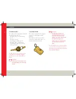
Page 8: ...he passenger airbag where provided CAUTION The radio control system may sometimes fail to operate due to interferences from nearby radio antennas transmitters which disturb the transmission frequencies For the system to resume operation move the vehicle several tens of metres Note Should you lose one or more radio controls follow the instructions given in the alarm system manual and contact the Fe...

Page 9: ...or safekeeping this code The PIN code can be used to deactivate the immobiliser system with the ignition key without using the radio control CAUTION Carefully read the instruction manual provided with the vehicle for proper use of the system Should you lose the PIN code you shall order a new radio control kit from the Ferrari Service Network 1 master 2 slaves together with the card showing the new...

Page 10: ...10 1 1 5 4 3 2 GENERAL IDENTIFICATION PLATES 1 Steering column plate 2 Chassis type and number 3 Engine type and number 4 Vehicle identification plate 5 Assembly number plate ...

Page 11: ...11 1 1 2 3 4 5 GENERAL ...

Page 12: ...12 1 A B C D E GENERAL LABELS A Low beams homologation label B ECE homologation label C Lubricants label D Paint code label E Unleaded fuel label ...

Page 13: ...13 1 F G H I L M GENERAL F High voltage label G Anti freeze label H Battery master switch label I Tyre pressure label L Tyre pressure monitoring system label M Oil level inspection label ...

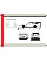
Page 14: ...70 1277 1632 1586 1935 GENERAL DIMENSIONS AND WEIGHTS Wheel base 2500 mm Max length 4550 mm Max width 1935 mm Max height 1277 mm Front track 1632 mm Rear track 1586 mm Kerb weight 1820 Kg Luggage compartment capacity 230 l ...

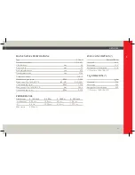
Page 15: ...rresponding r p m RPM 7 250 Max torque Dir 1999 99 CE Nm 588 6 Corresponding r p m RPM 5 250 PERFORMANCE Gearbox type 0 100 km h 0 400 m 0 1000 m 0 200 km h mechanical 4 25 sec 12 3 sec 22 sec 12 8 sec F1 4 2 sec 12 25 sec 21 9 sec 12 75 sec Max speed 320 km h FUEL CONSUMPTION litres per 100 km City cycle 34 5 Motorway 14 3 Average fuel consumption 21 8 Directive 1999 100 CE CO2 EMISSIONS g km Cit...

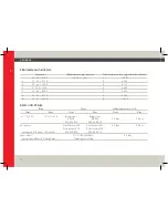
Page 16: ... 757 6 2 959 R 14 41 2 928 R 11 445 RIMS AND TYRES Rims Tyres Inflation pressure cold Front Rear Front Rear Front Rear 8 1 2 J X 19 10 1 2 J X 19 Bridgestone Bridgestone RE 050 RE 050 2 2 bar 2 0 bar 255 35 ZR19 305 30 ZR19 Snow tyres Pirelli Winter 210 Pirelli Winter 210 2 2 bar 2 2 bar Performance 210 Performance 210 Max Speed 210 km h 130 5 mph 255 35 ZR19 305 30 ZR19 Spare wheel T 115 70 R19 P...

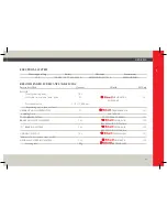
Page 17: ...ax 2 l HELIX ULTRA 151 SAE 5W 40 Oil consumption 1 2 l 1 000 km depending on conditions of use GEARBOX AND DIFFERENTIAL 5 l TRANSAXLE OIL 151 including lines SAE 75W 90 F1 GEARBOX SYSTEM 1 l FIAT TUTELA CS SPEED 151 BRAKE AND CLUTCH SYSTEM 1 3 l DONAX UB 152 BRAKE FLUID DOT4 Ultra F1 BRAKING SYSTEM 1 3 l DONAX UB 152 BRAKE FLUID DOT4 Ultra COOLING CIRCUIT 19 l GLYCOSHELL 151 Mixture of water and c...

Page 18: ... 20 l AIR CONDITIONING AND HEATING SYSTEM Compressor 265 cc HARRISON DIAVIA OLIO ISO 135 RL 150 Coolant 760 30 g R 134 A WINDSCREEN WASHER AND HEADLIGHT WASHER FLUID TANK 7 5 l Mixture of water and glass cleaner 153 Note for cleaning the windscreen use one phial of glass cleaner in summer and two in winter ...

Page 19: ...1 ...

Page 20: ...2 GENERAL SAFETY ABOUT YOUR VEHICLE ROOF DRIVING YOUR VEHICLE IN AN EMERGENCY CHECKS AND MAINTENANCE TABLE OF CONTENTS ...

Page 21: ...2 SAFETY Seat belts 22 Pretensioners 23 Child safety 23 Airbag 25 ABS 28 ASR 29 Inertia switch 30 ...

Page 22: ... the seat belts correctly fastened and adjusted at all times Correct use of the seat belts can reduce the risk of serious injury in the event of an accident The seat belts are automatic with three fastening points and an emergency inertia locking system on the winding unit equipped with pretensioner For an effective restraining action the seatbelt must be fastened correctly with the seatback in th...

Page 23: ... Network It is not permitted to remove or make modifications of any kind to the seat belts belt retractors and pretensioners Maintenance work involving strong impacts vibrations or heating of the pretensioner area may activate them vibrations caused by road bumps will not have this effect CHILD SAFETY Because of their size children are at greater risk than adults Suitable restraint or safety syste...

Page 24: ...on the front passenger seat if the airbag is enabled as this could cause serious injuries in the event of deployment Do not tamper with the seat belts or child restraint systems Established legislation in some countries already provides that children under 12 years of age may not travel in the front passenger seat The sticker B prohibits installing a child s seat facing rearwards on the front pass...

Page 25: ...bag system is composed of two instantly inflatable cushions one on the driver side in the centre of the steering wheel A and the other on the passenger side inside the dashboard B CAUTION When the ignition key is turned to position II see on page 65 the warning light C comes on and if no faults are detected goes off after 4 seconds If the warning light does not come on or if it stays on or if it c...

Page 26: ...ling objects e g cans bottles pipes etc placed on the airbag module covers or near them as they could be thrown towards the occupants by the inflating bag and may cause leakages of extremely hot gases When the system starts operating gases are released in the form of fumes together with the gas used for inflating the airbags These gases are not harmful CAUTION Always drive with your hands on the r...

Page 27: ...d Damaged or defective components of the airbag system cannot be repaired and must be replaced Improper operations performed on the system components may cause failures or deployment of the airbags with consequent damage The airbag system components have been specially designed only for this specific vehicle model Do not attempt to use them on other vehicles as this could cause serious injuries to...

Page 28: ...r pushes the brake pedal too sharply The system is composed of electro hydraulic unit EBD braking force distribution software four speed sensors on the wheels incorporated in the bearings These features add to the vehicle s standard braking system without changing its characteristics The driver will feel a sudden retreat of the brake pedal when the ABS activates When one of the wheels starts locki...

Page 29: ...distance may be reduced by as much as 40 CAUTION The ABS system does not exempt the driver from driving carefully and responsibly at all times The ABS system cannot compensate for driving at speeds that are excessively high for certain traffic or road surface conditions worn tyres worn components in the braking system or driving errors The purpose of the ABS system is solely to assist the driver i...

Page 30: ...s activated the system supports traction optimising vehicle performance Under low grip conditions e g ice sand etc do not select SPORT mode when the ASR is activated INERTIA SWITCH This is a safety switch positioned in the passenger compartment under the trim panel on the rear right hand side of the central console In the event of a collision it deactivates the fuel pump relays Activation of this ...

Page 31: ...31 2 SAFETY CAUTION The system can be reactivated by pressing button A on the upper part of the switch ...

Page 32: ...3 GENERAL SAFETY ABOUT YOUR VEHICLE ROOF DRIVING YOUR VEHICLE IN AN EMERGENCY CHECKS AND MAINTENANCE TABLE OF CONTENTS ...

Page 33: ...hes and buttons 57 Ignition switch 65 Handbrake lever 66 Seats 67 Fastening the seat belts 70 Manual deactivation of the passenger side airbag optional 71 Rear view mirrors 72 Internal lights 73 Ashtray Cigarette lighter 74 Sun visors 75 Glove compartment 75 Rear glove compartment 76 Engine compartment lid 77 Luggage compartment lid 78 Fuel tank cap 80 Air conditioning and heating system 82 ...

Page 34: ...34 3 ABOUT YOUR VEHICLE POSITION OF THE MAIN CONTROLS IN THE VEHICLE ...

Page 35: ...71 6 Air conditioning and heating system controls 82 7 Glove compartment opening buttons 75 8 Car stereo system 9 LOW GRIP mode button 108 Ref Control Page 10 Automatic gearshift mode switch 109 11 Roof tint level regulator 96 12 Roof opening closing switch 91 13 Reverse 1st gear engagement lever 104 14 Steering wheel position adjustment lever 53 15 Tyre pressure calibration button 61 16 Engine co...

Page 36: ...Exterior lights and direction indicator control lever 54 20 Gearbox control lever DOWN 102 Ref Control Page 21 Multi function display 45 22 Gearbox control lever UP 102 23 Windscreen and headlight wipers washer control lever 55 56 24 Ignition switch 65 For version with F1 gearbox only ...

Page 37: ...External rear view mirror adjustment control 73 28 Internal door opening handle 51 29 Door locking lever 51 30 Driver s seat position memory controls 69 31 Luggage compartment opening button 78 32 Fuel tank door opening button 80 Ref Control Page 33 Manual gearshift control lever 112 34 Cigarette lighter 74 35 Ashtray 74 ...

Page 38: ...E INSTRUMENT PANEL 1 Electronic speedometer 2 Revolution counter 3 Oil pressure gauge 4 Oil temperature gauge 5 Water temperature gauge 6 Fuel level gauge 7 Gear display 8 Warning lights 9 Multi function display For versions with F1 gearbox only ...

Page 39: ... VEHICLE 1 Electronic speedometer Indicates the driving speed in km h or mph Briefly press button A to view the total B or trip C mileage on the gauge To reset the trip odometer hold button A pressed down for at least 2 seconds ...

Page 40: ...on when the engine is running and pressure is too low In this case immediately switch off the engine and contact the Ferrari Service Network Avoid engine speeds in the red sector In the case of a mechanically controlled gearbox or when using SPORT mode with the F1 gearbox the ignition injection ECU temporarily cuts the power if these speeds are exceeded In Normal mode with the F1 gearbox the syste...

Page 41: ...ontact the Ferrari Service Network 5 Water temperature gauge Indicates the coolant temperature When the red warning light F comes on it indicates that the temperature is too high This light comes on when the temperature exceeds 125 C In this case reduce the engine speed immediately If the temperature remains high turn off the engine and contact the Ferrari Service Network 6 Fuel level gauge The sy...

Page 42: ...ith F1 gearbox only Incorporated in the revolution counter with the ignition key in position II it displays the gear engaged N Neutral R Reverse 1 1st gear 2 2nd gear 3 3rd gear 4 4th gear 5 5th gear 6 6th gear auto Automatic gearshift mode When the symbol _ is displayed it indicates a fault condition in the gearbox Please contact the Ferrari Service Network to have the necessary checks performed ...

Page 43: ...ously on the multi function display they indicate a failure of the electronic brake force distributor EBD If the warning light turns on while driving stop the vehicle check the level of fluid in the tank and contact the Ferrari Service Network Parking brake When the parking brake is engaged Airbag While driving to indicate a malfunction in the Airbag system and or in the seat belt pretensioners If...

Page 44: ...lights are activated When the hazard warning lights are turned on Position lights low beams When the position lights or low beams are turned on High beams When the high beams are turned on When the high beams are used to flash Parking lights When the parking light control switch is operated Rear fog lights When the rear fog lights are turned on Heated rear window and external rear view mirror defr...

Page 45: ...Multi function display signals The multi function display shows symbols relative to fault conditions and the state of the vehicle If multiple faults occur at the same time they are displayed for a period of time depending on their priority The signals from the tyre pressure monitoring system optional that may appear on the multi function display are described on page 48 The following symbols may b...

Page 46: ...urther information refer to page 122 Alternator failure The red symbol comes on when the battery needs to be recharged or if a fault has occurred in the power supply system Hazard warning lights If on it indicates that all the direction indicators are on at the same time Luggage compartment lid open If the red symbol comes on it means that the luggage compartment lid is open or not properly closed...

Page 47: ...ol comes on while driving it means that a system fault has occurred Have the vehicle checked by the Ferrari Service Network Fuel supply cut off If the amber symbol comes on it means that the inertia switch has activated and as a result the fuel supply is cut off see on page 30 ASR The amber symbol turns on to indicate that the ASR system has been disabled by means of the button relative see on pag...

Page 48: ...are connected to the electric system of the vehicle This wiring is positioned on the dashboard next to the engine compartment lid opening lever see on page 61 The system must be calibrated using the button on the dashboard after tyre replacement or inflation CAUTION The system warns the driver that there is a drop in tyre pressure However this does not exempt the driver from periodically checking ...

Page 49: ...ons in the section Replacing the wheels on page 128 when only one tyre has a puncture Puncture with wheel indication Activated when a puncture occurs indicating the tyre involved It remains on until the ignition key is turned to position 0 Follow the instructions in the section Replacing the wheels on page 128 when only one tyre has a puncture System calibration request Activated for a few seconds...

Page 50: ...er turning the ignition key to position II the warning light remains on for about 50 seconds and then goes off DOORS Introduction When a door is opened or closed the window automatically moves down by approximately 2 centimetres position A in order to avoid hitting the upper weather strip When the door is closed the window automatically moves back up position B until it meets the upper weather str...

Page 51: ...dow moves down to its target position and stops If the door is not opened after 20 seconds the window will move back up until it meets the weather strip Therefore to open the door release the handle and pull it again Door open indicator Each door is equipped with a red light F on the rear part and a light G on the lower part which come on when the door is opened These lights turn on automatically ...

Page 52: ...n a second time Passenger side power window Press button B to move the window up or down This button allows only manual operation when button B is released the window stops in the position reached When the door is open the window can only rise to its target position to prevent the door from colliding with the upper weather strip when it is closed CAUTION Improper use of the power windows can be da...

Page 53: ... STEERING WHEEL LEVERS When operating the left hand lever the exterior lights and direction indicators come on The exterior lights and the direction indicators only work when the ignition key is in position II Adjust the steering wheel position Lock the steering wheel by pushing the lever A back to the initial position CAUTION Do not adjust the steering wheel when the vehicle is moving ...

Page 54: ... to its central position when the steering wheel is straightened Position A lever at rest Direction indicators off External lights Position 0 Lights off Position 1 lever turned by one click Position lights and number plate lights on the relevant warning light also illuminates and the instrument panel is backlit Position 2 lever turned by two clicks Low beams on Flashing the headlights You can flas...

Page 55: ...ition key in position II The headlight washers only work with the low beams on Position B lever up Right hand side indicators Position C lever down Left hand side indicators Windscreen wipers Position 0 Windscreen wipers off Position lever lowered by one click Adjustable intermittent operation Position I lever lowered by two clicks Continuous slow operation Position II lever lowered by three click...

Page 56: ... towards the steering wheel A to simultaneously activate the windscreen washer and the windscreen wipers When the lever is released the windscreen washer stops while the windscreen wipers continue for a few more strokes Headlight washers With the low beams on pull the lever towards the steering wheel A to activate the headlight washer For better cleaning use the headlight washers when the vehicle ...

Page 57: ...e direction indicators will start flashing simultaneously These lights will operate with the ignition key in any position Their activation is indicated by the symbol B appearing on the multi function display and by the intermittent illumination of the warning light C and of the switch A For deactivation press the switch once again ...

Page 58: ...he steering wheel in position with the horn symbol Parking lights They are activated by pressing switch D The position lights will be turned on These lights will operate with the ignition key in any position Their activation is indicated by the illumination of the warning light E For deactivation press the switch once again ...

Page 59: ... by the words ASR ACTIVE H appearing on the multi function display for at least 4 seconds CAUTION Under medium or low grip conditions e g wet icy sandy etc road surfaces keep the ASR system active and do not select SPORT mode In any case we advise you to keep the ASR system enabled even under normal driving conditions CAUTION If the symbol G is displayed when the ASR is active it means that the sy...

Page 60: ... vehicle the driver is always obliged to observe the essential rules for safe driving SPORT mode The driver can change the vehicle setting depending on his her own driving style Press button K to activate or deactivate SPORT mode Its activation is indicated by the illumination of the warning light L SPORT mode is the ideal setting for racing style driving under high grip conditions while normal mo...

Page 61: ...of the warning lights N and O 30 minutes after activation the control button will automatically be turned off It is however advisable to turn it off when the demisting or defrosting procedure has been completed Tyre pressure calibration button To calibrate the system with the ignition key in position II press button P near the engine compartment lid opening handle for 4 10 seconds ...

Page 62: ...riefly press less than 2 seconds the left hand button R to sequentially switch between the various functions shown on the display outside temperature LH front tyre pressure FL RH front tyre pressure FR RH rear tyre pressure RR LH rear tyre pressure RL If one or more alarm symbols illuminate on the multi function display briefly press the LH button R to access the above mentioned functions using th...

Page 63: ...g the LH button from the minute setting option Instrument panel lighting Press the left hand button R at length to view the symbol U on the multi function display Briefly press the right hand button S to adjust the brightness of the instrument panel to a value between 0 and 30 Briefly press the right hand button S to switch between total and trip odometer if you press the RH button S at length the...

Page 64: ...ed the clock stops When the battery is reconnected the exact time must be reset using the multi function display scroll buttons see on page 62 If one or more alarm symbols appear on the multi function display the time will not be displayed as long as the alarm is active Considering that while driving more than one indicator lights may be turned on simultaneously the time and the ASR or Fuel reserv...

Page 65: ... locked The hazard warning lights and the parking lights can be turned on To facilitate steering wheel release turn the steering wheel slightly in both directions while turning the ignition key Position II Ignition Turning the key to this position the multi function display will run a check cycle on the signals coming from the vehicle systems If no malfunctions are found the words CHECK OK light u...

Page 66: ...the first steer Always remove the key from the ignition when you get out of the vehicle Never leave children unattended in the vehicle HANDBRAKE LEVER To engage the handbrake pull the lever A fully upwards until the rear wheels lock With the ignition key in position II the warning light B comes on to indicate that the handbrake is engaged ...

Page 67: ...tton pressed The warning light B will switch off when the handbrake is fully released CAUTION Always use the handbrake when the vehicle is parked For further information see on page 113 The seat position can be electrically adjusted using controls A and B Using control A you can slide the seat forward and backward and turning it clockwise or anticlockwise you can raise or lower the seat cushion Us...

Page 68: ...t in such a way that the centre of the headrest is level with the nape and not the neck Use the lever E to tilt the backrest forward Skin saver device To prevent the backrest from touching the rear panel of the passenger compartment when moving the seats backward a switch F has been fitted on the panel behind each seat When the backrest depresses this switch it stops the backward movement of the s...

Page 69: ...with the door closed press the required button until you hear the tone indicating the seat stop Driver s seat position memory This device allows you to memorise and recall two different seat positions You can memorise the seat position only when the ignition is in position II Adjust seat position as described in the previous points Then simultaneously press the button M and one of the buttons 1 or...

Page 70: ...cing type seats optional The seats can be slid forward and backward by pulling the lever G upward Turn the knob H to obtain the desired position of the backrest FASTENING THE SEAT BELTS Adjust the seat and headrest properly Grip the buckle A slowly pull the belt and insert the latch into the buckle B If the belt locks while you are pulling it out let it wind back briefly and pull it out again with...

Page 71: ... the belt latch A back to its rest position MANUAL DEACTIVATION OF THE PASSENGER SIDE AIRBAG optional If a child is to be transported in the front passenger seat always deactivate the passenger side airbag before fitting the child seat The airbag can be deactivated by means of the relative key operated switch located on the right hand side of the dashboard The switch is only accessible with the do...

Page 72: ... airbag is reactivated With the door open the key can be inserted and extracted in both positions REAR VIEW MIRRORS Interior rear view mirror This can be adjusted manually To set the mirror in the anti dazzle position push lever A forward CAUTION If the passenger side airbag is deactivated because you are carrying a passenger who is considered by the laws in force to be at risk and who must theref...

Page 73: ...CAUTION The mirrors must be always positioned correctly while driving Do not adjust the mirrors when the vehicle is moving INTERNAL LIGHTS You can select when the dome light should come on with the switches found on the windscreen upper cross member on when the doors are closed off automatically on when the doors are unlocked for about 10 seconds and when one of the doors is opened for about 3 min...

Page 74: ...the cigarette lighter into place by fully pushing down the button B After reaching the required temperature the cigarette lighter is automatically released to its initial position and is ready to be used CAUTION Do not use the cigarette lighter seat as a power socket for electrical items of any kind The cigarette lighter C reaches high temperatures Handle it with care to avoid risk of burns and fi...

Page 75: ...ing them downwards On the back of the sun visor there is a small map pocket GLOVE COMPARTMENT It is found on the dashboard on the passenger side and has a key lock A The glove compartment can be opened closed with the ignition key To access the compartment press on the lock ...

Page 76: ...by means of an actuator and the thrust of an internal spring which holds it in this position To close it push it into the closed position and stop pushing when you hear the locking click If you continue to push the spring thrust will reopen the glove compartment In the event that the actuator fails or the battery is flat the glove compartment can be opened by pulling the emergency opening string p...

Page 77: ...mn Disengage the lid retaining lever B found in the front central area of the vehicle by pushing it upwards The lid is kept in the open position by two gas struts C Closing Lower the lid until it is closed and press down near the lock until you hear it click in place CAUTION Always check that the lid is closed properly to prevent it from opening while driving ...

Page 78: ...h until the protective cap D is removed from its seat Through the opening where the cap was removed grip the ring E with your fingers and pull it downwards LUGGAGE COMPARTMENT LID The luggage compartment lid can be opened with the roof in the fully closed or fully open position Opening To open the engine compartment lid push the button A ...

Page 79: ...e the closing mechanism and or the lid itself Lift the luggage compartment lid To facilitate the operation there are two gas struts B that help pushing the luggage compartment lid upward and hold it in this position The luggage compartment is illuminated by an internal light that comes on automatically when the luggage compartment lid is opened Emergency opening If the button A does not work pull ...

Page 80: ...nticlockwise and put it in its seat C Always turn off the engine during refuelling Take extreme care when removing the cap Do not smoke or use open flames when refuelling furthermore inhaling vapours can be harmful Opening Push the release button A to open the fuel tank door ...

Page 81: ...ightly and close the fuel tank door Make sure that the cord D does not hang out of the fuel tank door Emergency opening If the button A does not work the fuel tank door can be opened manually with the ring E located on the right hand side of the luggage compartment ...

Page 82: ...ws 3 Adjustable central and side vents 4 Air vents for foot area 5 Sun radiation sensor 6 Outside temperature sensor 7 Passenger compartment temperature sensor 8 Air conditioning and heating system controls Operating modes Automatic This mode automatically adjusts humidity and ventilation according to the selected temperature Manual This mode allows manual adjustment using the controls ...

Page 83: ...has three operating modes Automatic The air flow distribution is controlled by the electronic system depending on the ambient conditions and the selected temperature Manual The air flow is directed towards four different areas Fast demisting defrosting This mode allows the user to demist and or defrost the windscreen and the side windows Temperature selection control This is used to set the desire...

Page 84: ...es air heating or cooling Prolonged use is not advisable Once the internal temperature has stabilised at the desired level you are advised not to change the position of the temperature selection switch unless the external temperature changes drastically Changing the position of the temperature selection switch results in a certain difference between the temperature in the passenger compartment and...

Page 85: ...3 ...

Page 86: ...4 GENERAL SAFETY ABOUT YOUR VEHICLE ROOF DRIVING YOUR VEHICLE IN AN EMERGENCY CHECKS AND MAINTENANCE TABLE OF CONTENTS ...

Page 87: ...F System description 88 Controls and warning lights 90 Opening sequence 92 Closing sequence 93 Emergency procedure 94 Special warnings 95 Adjusting the roof tint level 96 Roof cover 96 Cleaning the glass 97 ...

Page 88: ...lid by two rear foldaway locks driven by a single motor Moreover when the roof is open the rear window acts as a wind deflector The roof is operated by two electric motors mounted on either side of the roof which drive by means of a toothed belt a pulley installed in position with the fulcrum point In addition an electromagnetic clutch is fitted on either side so that the roof can be moved manuall...

Page 89: ...ctivation and during operation that people or things are at a safe distance from the roof s movable parts Never leave children unattended in the vehicle When the roof is operated the driver and passenger must remain properly seated in the their seats The roof may be opened closed only under the following conditions vehicle stationary parking brake engaged luggage compartment lid fully closed suffi...

Page 90: ... upper cross member of the windscreen Closing lower the handle and rotate it clockwise to the right until it stops After rotating the handle tilt it guiding it to the rest position Opening lower the handle and rotate it anticlockwise to the left until it stops After rotating the handle tilt it guiding it to the rest position ...

Page 91: ...by an amber warning light C that lights up on the instrument panel If the toggle switch B is released before the opening or closing cycle has been completed the roof stops and the clutches remain engaged If the opening closing toggle switch is not pressed within 10 minutes the system reverts to a Roof Unknown condition and the clutches are released after 2 seconds releasing the roof This condition...

Page 92: ...r by operating the handle A Push the toggle switch B backward to start opening the roof the entire action takes approximately 10 seconds The side windows lower fully they cannot be operated until the procedure has been completed When the roof has reached the fully open position the windows move back up During this last stage the toggle switch B can be released and the cycle may be considered compl...

Page 93: ...he front end of the roof to the windscreen cross member close the locks on the windscreen cross member by operating the handle A CAUTION This action is essential for the safety of the occupants and to avoid damaging the vehicle When the toggle switch B is pushed in the closing direction again the side windows move back up and the closing cycle may be considered complete The closing cycle can be in...

Page 94: ...ting the safety handle A If the fault persists after closing the roof manually contact the Ferrari Service Network If the battery is accidentally disconnected or it discharges during the roof opening closing cycle the system goes to the Initialisation condition and the ECU must be reset after recharging the battery Follow the procedure below Manually close the roof as described below Reconnect the...

Page 95: ...ent can be accessed only when the roof is fully open or fully closed see on page 78 Roof operation is stopped in the following cases When the toggle switch is released When the parking brake is released When the luggage compartment lid is opened When the ignition key is turned to position 0 When the battery voltage is below 10 5V In the above cases the failure warning light on the instrument panel...

Page 96: ...rder to limit the transmission of solar energy when the vehicle stays in the sun for a long period of time the system sets the roff tint to an intermediate level each time the ignition key is turned to 0 Stop Turn the adjustment dial 1 anticlockwise to increase the roof transparency and vice versa to decrease it Adjustments are only possible with the ignition key in position II Ignition When the k...

Page 97: ...uggage compartment open the zippers C and unfasten the buttons A from the roof pins Fold the cover on the zippers and put it in its bag Put the bag in its place in the front of the luggage compartment CLEANING THE GLASS The roof glass does not require any special treatment Use window cleaners and do not use abrasive cloths sponges or other tools that may scratch the surface ...

Page 98: ...5 GENERAL SAFETY ABOUT YOUR VEHICLE ROOF DRIVING YOUR VEHICLE IN AN EMERGENCY CHECKS AND MAINTENANCE TABLE OF CONTENTS ...

Page 99: ...ehicle F1 gearbox 104 Gearshifting F1 gearbox 106 Stopping the vehicle F1 gearbox 107 Turning off the engine and the system F1 gearbox 107 Other system functions F1 gearbox 108 Push start F1 gearbox 111 Starting and warming up the engine Mechanical gearbox 112 Driving the vehicle Mechanical gearbox 112 While driving Mechanical gearbox 113 Parking 114 Safe driving 114 Respecting the environment 117...

Page 100: ...egular intervals and always before long trips tyre pressure and condition levels of fluids and lubricants condition of the windscreen wiper blades warning lights and exterior lights operation In any case it is advisable to perform these checks at least every 1000 km and to always comply with the maintenance schedule It is also advisable to clean the glass on the exterior lights and all other glass...

Page 101: ... the ignition key is inserted The failure warning light B may also flash for a short period of time 10 sec and then switch off the system completes the start up phase and then starts correctly Avoid giving any commands to the system during this stage CAUTION If the warning light B continues flashing without going off turn off the system and restart If the failure persists contact the Ferrari Servi...

Page 102: ...y there is a system failure When the engine is off you can engage 1st reverse R and neutral N Holding the brake pedal down you must proceed as follows N Neutral pull both levers found behind the steering wheel R Reverse lift and pull the lever R towards the rear of the vehicle CAUTION Hold the lever R pulled backward until the letter R appears on the display Engaging 1st gear push the lever R forw...

Page 103: ...tion 0 wait a few seconds and retry Set the gear to neutral by pulling both levers UP and DOWN towards the steering wheel and check that the gear display indicates N not flashing Turn the key to position III and release it as soon as the engine has started After the engine has started the words Check OK will be displayed Do not hold the key in position III for a prolonged time If the engine does n...

Page 104: ...r or move the lever R forward CAUTION Use 1st gear to park and for uphill starts Release the brake pedal and press the accelerator to start off With the engine running and the vehicle stationary you can change directly from 1st or 2nd gear to reverse gear by operating the lever R from reverse gear to 1st gear by pushing the lever C forward or pulling the lever UP towards the steering wheel When re...

Page 105: ...n the vehicle is stationary on a hill or during the pick up manoeuvre In these cases release the accelerator pedal and use only the brake pedal to stop the vehicle or where possible start off immediately Important When the vehicle is stationary with a gear engaged always keep the brake pedal pressed until ready for departure Do not rev the engine using the accelerator pedal when you start off Shif...

Page 106: ...ue to engine overrevving The system automatically engages a higher gear if the accelerator pedal is pressed and the engine approaches the runaway speed rate overrevving This condition does not occur with the system in SPORT mode Downshifting DOWN Use the left hand DOWN lever even without releasing the accelerator pedal A DOWNshift request is not accepted if engagement of the requested gear will fo...

Page 107: ...e system automatically engages 1st gear unless N has already bee requested With the vehicle stationary and the engine running hold the brake pedal down until you are ready to start off again TURNING OFF THE ENGINE AND THE SYSTEM F1 gearbox The engine can be turned off with the system in N or a gear engaged After turning the ignition key from position II to position 0 the display remains on for a f...

Page 108: ...F1 gearbox LOW GRIP mode This mode may be used when the road surface is particularly slippery e g snow ice and it is activated or deactivated using the switch D The relevant warning light E on the instrument panel will come on While driving the system automatically switches to a higher gear if the engine reaches the pre established speed rate 3200 RPM The LOW GRIP mode has priority over the other ...

Page 109: ...e selecting LOW GRIP mode Automatic gearshift mode This mode is activated or deactivated pressing the AUTO button The word auto will light up on the gear display on the instrument panel and the system will automatically shift the gears UP and DOWN according to the vehicle speed the engine RPM and the torque power requested by the driver The automatic gearshift mode has priority over the SPORT mode...

Page 110: ... warning light will light up on the dashboard To switch back from SPORT to Normal mode operate the switch again Since SPORT mode has a lower priority than LOW GRIP and AUTO modes if these are already active when SPORT mode is activated the system will ignore the command even if the relevant warning light comes on CAUTION SPORT mode is characterised by a stiffening of the suspensions and faster gea...

Page 111: ...te the other LOW GRIP and AUTO operating modes before selecting SPORT mode In the event that the control lever cluster is malfunctioning in addition to activating the buzzer and turning on the failure warning light B the system auto selects the AUTO mode and any further gearshift requests will be ignored including N and reverse If the malfunction persists contact the Ferrari Service Network as soo...

Page 112: ... the vehicle fails to start turn the key back to position 0 before repeating the procedure In the event that the words Check OK are not displayed turn the key back to position 0 wait a few seconds and retry After the engine has started the words Check OK will be displayed If the engine fails to start after several attempts check for one of the following causes insufficient speed of the starter mot...

Page 113: ...er approaches peak speed the red zone the driver must be very careful to avoid exceeding that limit In normal conditions all the red and amber light indicators for the suspension and ASR systems on the multi function display must be off When on these LEDs indicate a malfunction in the corresponding system Ensure proper functioning of the various devices by checking the relevant control gauges CAUT...

Page 114: ...he best driving position Adjust the backrest so that your chest is upright and your head is as close to the headrest as possible Carefully adjust the headrest so that your head and not your neck is resting against it Ensure that nothing e g mat covers etc is blocking the pedals Check that the lights and headlights are working properly Ensure that any child restraint systems e g child seats cradles...

Page 115: ... your limbs and refresh yourself and avoid driving for hours on end Keep a constant air circulation in the passenger compartment Never coast downhill with the engine off in these conditions the engine brake brake servo and power steering cannot be used braking requires greater pressure on the pedal and steering will be harder Driving at night When you are travelling at night follow these fundament...

Page 116: ...og banks follow these rules Keep a moderate speed Turn on the low beams also during the day and use the rear fog light Avoid using the high beams On stretches where visibility is good turn off the rear fog light as it is very bright and may be annoying for the occupants of the vehicles behind you Remember that fog makes the road damp and therefore all manoeuvres are more difficult and what is more...

Page 117: ...tion at the same time This feature is affected by the physical limits and lateral grip of the tyres When the ABS is activated you will feel a slight pulsing of the brake pedal during emergency braking or in low grip conditions Do not release the pedal but continue to push it to give continuity to the braking action The ABS prevents the wheels from locking but it does not increase the physical limi...

Page 118: ...nt increase in noxious emissions Intense traffic conditions involving the use of lower gears or driving in urban areas with numerous traffic lights can increase the emission of noxious substances in the environment During prolonged stops e g at level crossings it is recommended that you turn the engine off Anti pollution device maintenance The correct operation of the anti pollution devices not on...

Page 119: ...5 ...

Page 120: ...6 GENERAL SAFETY ABOUT YOUR VEHICLE ROOF DRIVING YOUR VEHICLE IN AN EMERGENCY CHECKS AND MAINTENANCE TABLE OF CONTENTS ...

Page 121: ...on alarm devices 123 Replacing the brake pads and discs 123 Toolkit 124 Replacing the wheels 128 Replacing the headlight bulbs 130 Replacing the taillight bulbs 133 Light bulbs 135 Replacing a fuse relay 136 Battery master switch 144 Checking the battery 145 Towing the vehicle 146 ...

Page 122: ...flash or stay on permanently The activation of the SLOW DOWN symbol is controlled by the thermocouple through the Motronic ECU CAUTION If the warning light flashes the temperature of the catalytic converters is too high Slow down immediately and go to a service centre to have the malfunction corrected If the warning light remains on the temperature in the catalytic converters has reached a dangero...

Page 123: ...ngine check system failure comes on engine performance may also considerably be reduced Drive carefully avoiding sudden acceleration and high speeds REPLACING THE BRAKE PADS AND DISCS The brake failure warning light will come on to indicate excessive wear of the brake pads which must be replaced immediately CAUTION In order to ensure the quality of components and accurate installation it is recomm...

Page 124: ...k where skilled staff will check whether the brake discs need to be replaced TOOLKIT Toolkit bag The toolkit is found in the luggage compartment and it contains all the necessary tools for a first repair work in case of failure water pump and hydraulic steering driving belt A C compressor and alternator driving belt set of flat wrenches insulated cutting pliers screwdriver for slotted screws screw...

Page 125: ... is to be used to temporarily repair only one tyre punctured by small objects the kit may not be useful in the case of large punctures or tearing CAUTION Keep the kit in its box and out of the reach of children Do not inhale or swallow the fluid contained in the cartridge and avoid contact with the skin and eyes The repaired tyre must be replaced as soon as possible and the workshop personnel must...

Page 126: ... so that the socket is powered then activate the compressor by pressing the switch D To inflate repair the tyre successfully the lever terminal part H must be fitted into the relevant union J Stop the compressor when the pressure indicated on the pressure gauge C reaches the pressure specified for that tyre see on page 16 Remove the union G and screw the cap back onto the valve ...

Page 127: ...e the sensor replaced by the Ferrari Service Network The kit can also be used only to inflate a tyre using the lever terminal part H Remove the terminal part H from the union J on the cartridge and insert it in the wheel valve Lower the lever K and start the compressor Inflate to the indicated pressure see on page 16 Replacing the puncture repair fluid cartridge Remove the terminal part H from the...

Page 128: ...heels need to be replaced proceed as follows Replace the stud bolts with damaged thread or cone Carefully clean the stud bolts before fitting Absolutely do not lubricate the contact surfaces between the stud bolt and the wheel rim and between the wheel rim and the brake disk In order not to remove the anti lock coating do not clean the wheel rim cones with solvents or aggressive products Spare whe...

Page 129: ... to comply with these instructions could lead to loss of control of the vehicle and consequently damage to the vehicle and injuries to the occupants Replacing a wheel Position the vehicle on an even surface then engage 1st gear and lock the rear wheels with the parking brake If necessary turn on the hazard lights and place the hazard triangle at the prescribed distance Take the spare wheel and too...

Page 130: ...e stud bolts with the torque wrench tightening them to a torque of 100 Nm CAUTION The spare wheel is not equipped with a tyre pressure monitoring sensor see label on spare wheel bag After installation it is not monitored by the system but it does comply with International Regulation ECE R64 01 Once fitted we recommend you go to the nearest Centre of the Ferrari Service Network REPLACING THE HEADLI...

Page 131: ...cing the high beam bulbs Do not touch the halogen lamps with your hands if this happens accidentally clean the bulb with a cloth moistened in alcohol Remove the plastic cover A Detach the connector B of the bulb to be replaced Release the fixing clip C and remove the bulb D Fit the new bulb refit the fixing clip reattach the connector and reposition the plastic cover ...

Page 132: ...ement contact the Ferrari Service Network Replacing the position light bulbs Detach the connector E from the bulb holder F Turn and slide the bulb holder out of its seat on the headlight Remove the bulb and properly position the new bulb Refit the bulb holder in its seat and turn it clockwise until it locks Refit the connector Replacing the side direction indicator bulbs Remove the cover G being c...

Page 133: ...IGHT BULBS A Number plate lights B Position and stop light C Direction indicator light D Reverse light E Rear fog light F Auxiliary stop light Set the battery master switch to OFF When the operation has been completed reconnect the battery see on page 144 ...

Page 134: ...and remove the cover H Undo the two screws I that secure the bulb holder to the headlight Remove the bulb holder L Remove the bulb M turning it anticlockwise Replace the bulb and refit the bulb holder and the cover Replacing the auxiliary stop light bulbs For replacement of the light cluster contact the Ferrari Service Network ...

Page 135: ...HB3 60W Low beams gas discharge Front position lights incandescent W5W Front direction indicator lights incandescent PY21W Side direction indicator lights incandescent T4W Number plate lights incandescent R5W Rear position and stop lights incandescent P21 5W Rear direction indicator lights incandescent P21W Rear fog lights incandescent P21 5W Reverse lights incandescent P21W Auxiliary stop lights ...

Page 136: ...ed contact the Ferrari Service Network When replacing a fuse always use fuses of the same amperage same colour Spare fuses are found in the toolkit To remove the fuses use the pliers C provided in the toolkit bag Fuse colours dark yellow brown red light blue yellow white green Ampere A5 A7 5 A10 A15 A20 A25 A30 Maxi fuse colours yellow green orange red blue Ampere A20 A30 A40 A50 A60 ...

Page 137: ...he fuse and relay boxes A B C D E F Fuses and relays inside passenger compartment passenger side G Fuses and relays inside passenger compartment driver side H L M Fuses and relays inside engine compartment Symbol legend 30 permanent battery 15 key operated ...

Page 138: ... F41 F44 F43 R18 R17 A B C D E F IN AN EMERGENCY Remove the box covers 3 to access the fuses and relays CAUTION We recommend that you open only the boxes in which you need to work to avoid damaging other components Fuses and relays inside passenger compartment passenger side To access these fuses lower the protective footrest panel 1 found under the mat on the passenger side Rotate the two catches...

Page 139: ... hand and rear right hand position light Ref Use R5 Low beams and headlight washer activation switch R6 High beams R7 Position lights R8 Parking lights The box B contains the following fuses F and relays R Ref Amp Use F13 7 5 Reverse lights F14 7 5 Rear fog lights F15 5 Internal lights and number plate lights F16 5 30 instrument F17 10 Luggage compartment and fuel tank door actuator F18 15 Ignitio...

Page 140: ...lable for amplifier F28 30 30 direction indicator timer F29 15 30 passenger seat F30 10 30 luggage compartment dome and door lights F31 20 30 F1 ECU F32 20 30 power supply for first roof operating motor F33 10 15 ABS ASR ECU F34 5 15 instrument The box D contains the following fuses F and relays R Ref Amp Use F41 30 Starter motor and R14 relay coil F42 30 30 horn compressor F43 10 Stop lights and ...

Page 141: ...not connected upon ignition R15 Air conditioning compressor R16 Position available The box F contains the following fuses F and relays R Ref Amp Use F46 15 15 power supply for roof and electrochromic glass ECU F47 30 30 right hand Motronic master F48 15 Right hand oxygen sensor solenoid valve F49 7 5 30 right hand Motronic F50 10 15 right hand Motronic master relay F51 10 15 right hand Motronic re...

Page 142: ...ng panel To access these fuses remove the cover 4 The box contains the following fuses F and relays R Ref Amp Use F1 30 30 left hand Motronic master F2 15 Left hand oxygen sensor solenoid valve F3 7 5 30 left hand Motronic F4 10 15 left hand Motronic master relay F5 10 15 left hand Motronic relay R2 R3 R3 F6 15 Left hand injectors and coils Ref Use R1 Left hand Motronic master R2 Left hand fuel pu...

Page 143: ...nd water fan relay 7 Right hand water fan relay 8 Headlight washer timer 9 Air pump relay The boxes L and M are located next to each other in the engine compartment near the battery master switch To access these fuses remove the covers 10 The box L contains the following maxi fuses MF Ref Amp Use MF1 40 Right hand fan MF2 40 Left hand fan MF3 80 General MF4 60 ABS The box M contains the following ...

Page 144: ...d by means of the master switch A located in the engine compartment Disconnection of the battery is advised if the vehicle is not used for long periods of time Consult the chapter If the vehicle is stored for long periods in the section Checks and maintenance Each time the battery is reconnected before starting the engine wait at least 10 seconds with the ignition key in position II to allow the e...

Page 145: ...y from sources of heat and do not use open flames or create sparks near it Recharging the battery CAUTION The battery should be recharged in a well ventilated area and away from any flammable materials Batteries can produce combustible gases Do not smoke use open flames or create sparks near the battery Proceed as follows using a lead acid battery charger Set the battery master switch to OFF Disco...

Page 146: ... B Take the tow hook out of the toolkit bag Screw the hook tightly into its seat B Position the gearshift lever in neutral N for vehicles with F1 gearbox CAUTION The applicable driving and traffic regulations must be followed when the vehicle is being towed Do not tow the vehicle using a hook attached to the suspension levers and wheel rims but only onto the tow hook properly fitted in its seat Ho...

Page 147: ...6 ...

Page 148: ...7 GENERAL SAFETY ABOUT YOUR VEHICLE ROOF DRIVING YOUR VEHICLE IN AN EMERGENCY CHECKS AND MAINTENANCE TABLE OF CONTENTS ...

Page 149: ... Maintenance 150 Level checks 150 Windscreen wipers 153 Wheels and tyres 154 Maintenance of the seat belts and pretensioners 155 Cleaning the vehicle 156 If the vehicle is stored for long periods 158 Anti corrosion coating 158 ...

Page 150: ... checking operations indicated in the WARRANTY BOOKLET AND SERVICE TIME SCHEDULE It is however advisable to immediately report to our Service Centres any small fault which may occur during use of the vehicle e g small fluid leaks and not wait until the next service is due to correct the problem It is required to have the periodic service performed at least once a year even if the specified mileage...

Page 151: ...oil taking care not to exceed the MAX level on the dipstick Screw the cap B back on tightly Gearbox and F1 gearbox system oil It is recommended to have the oil level checked at a Ferrari Service Network Centre or by skilled staff Coolant CAUTION This procedure must always be performed when the engine is cold Never remove the cap C from the expansion tank when the engine is running or hot Remove th...

Page 152: ...e system s rubber gaskets beyond repair Do not use fluids other than those already contained in the system for topping up When the system has been topped up screw the cap back on and reconnect the electric system Brake clutch oil Check that the fluid in the tank is near the MAX level If the level is low unscrew the cap A and top up with the recommended oil taken from a sealed container CAUTION The...

Page 153: ...age the wiper blades avoid using them when the windscreen is dry the blades are stuck to the windscreen due to sub zero temperatures there are traces of snow on the windscreen or the wiper arms there are deposits on the windscreen The wiper blades must be cleaned periodically and checked for wear Replacing the wiper blades Turn on the windscreen wipers and stop them ignition key in position 0 when...

Page 154: ...cause damage to the tyres which may not always be visible Check the tyres regularly for any signs of damage e g scratches cuts cracks bulges etc Sharp objects that have penetrated the tyres may have caused damage which can only be diagnosed by removing the tyre Have any damage inspected by an expert as it may considerably reduce tyre life Remember that tyres deteriorate with time even if used litt...

Page 155: ...ice Network check the wheel toe in and camber MAINTENANCE OF THE SEAT BELTS AND PRETENSIONERS Periodically check that the screws on the anchoring points are tight and that the belt is in perfect condition and slides smoothly The belt must be kept clean any dirt on the belt could affect the efficiency of the belt retractor To clean the seat belt wash it by hand with mild soap and water and let it d...

Page 156: ...any water to drain The underbody and the lower surfaces of the vehicle should be cleaned regularly and more frequently at least once a week if the vehicle is used on salty or rough roads The vehicle should be cleaned thoroughly and carefully cleaning that only wets the vehicle without removing dirt or mud completely can prove damaging to the body The vehicle must be washed regularly with adequate ...

Page 157: ... organic substances such as petrol kerosene petroleum acetone or solvents Cleaning the interior Cleaning and care of the leather upholstery Suitable and regular treatment at least 3 4 times a year will ensure that the original quality natural characteristics and softness of the leather upholstery in your Ferrari is maintained unaltered over time With this in mind specific leather care products are...

Page 158: ...ttery disconnected the battery must be recharged at least every three months Protect the vehicle with a breathable fabric cover avoiding materials that would prevent any dampness on the bodywork from evaporating Before using the vehicle again after long periods of inactivity adjust the tyre pressure to the specified pressure and check the fluid levels of all the systems ANTI CORROSION COATING Alum...

Page 159: ...7 ...

Page 160: ...8 GENERAL SAFETY ABOUT YOUR VEHICLE ROOF DRIVING YOUR VEHICLE IN AN EMERGENCY CHECKS AND MAINTENANCE TABLE OF CONTENTS ...

Page 161: ...8 TABLE OF CONTENTS ...

Page 162: ...y 95 Dimensions and weights 14 Direction indicators 54 Displaying messages from the tyre pressure monitoring system 48 Doors 50 Driver side power window 52 Driver s seat position memory 69 Driving at night 115 Driving in fog 116 Driving in the rain 116 Driving on mountain roads 116 Driving on snowy and icy roads 117 Driving styles 118 Driving the vehicle F1 gearbox 104 Driving the vehicle Mechanic...

Page 163: ...on with the engine off F1 gearbox 102 Parking 113 Parking lights button 58 Particular driving conditions 118 Passenger side power window 52 Performance 15 PIN code 9 Position of the main controls in the vehicle 34 Power windows 52 Pretensioners 23 Push start F1 gearbox 111 Racing type seats 70 Rear fog lights button 60 Rear glove compartment 76 Recharging the battery 145 Recommended lubricants and...

Page 164: ...ing the system F1 gearbox 101 Steering wheel position adjustment 53 Stopping the vehicle F1 gearbox 107 Sun visors 75 Toolkit 124 Towing the vehicle 146 Transmission ratios 16 Turning off the engine and the system F1 gearbox 107 Tyre pressure calibration button 61 Updating 4 Vehicle keys 8 Warning lights 43 Warranty booklet 150 Water temperature gauge 41 Wheel alignment check and adjustment 155 Wh...

Page 165: ...8 ...

Page 166: ...any time for either technical or commercial reasons Contact the nearest authorised Dealer or Ferrari for any further information you may require For efficiency and safety as well as for preserving the vehicle s value it is advisable not to modify the vehicle equipment unless you use parts of the approved type COPYRIGHT Technical Service Dept Via Abetone Inferiore 4 41053 Maranello Modena Code No 6...

Reviews: