background image

Summary of Contents for 612 scaglietti

Page 1: ......

Page 2: ...1 USO E MANUTENZIONE OWNER S MANUAL USO Y MANTENIMIENTO ...

Page 3: ...mmend you have all the maintenance and checks carried out at our Agencies or at our authorised workshops astheyhaveskilledstaffandsuitableequip ment See Sales and Service Organisation handbook for loca tionsoftheDEALERSandAUTHORISEDFERRARISERVICECEN TRES The FERRARI TECHNICAL SERVICE is at your complete dis posal for any information and suggestions Debido a la gran potencia desarrollada porelmotor...

Page 4: ...tfitting To facilitate reading and rapid use the topics are sub dividedintosectionsandchapters Theimportantparts requiring particular attention are easily identifiable in the sections and chapters Extremecautionrequired Failuretocom ply with the instructions could cause ha zardoussituationsinvolvingpersonalandvehi cle safety Importantnote warningaimedatpreventinganydamage to the vehicle and thus h...

Page 5: ...ctronically controlled brake force distributor CST TRACTION STABILITY CONTROL ECU ELECTRONIC CONTROL UNIT F1 FORMULA 1 Electronically controlled gear box designed with the same technology used in the racing sector TFT THIN FILM TRANSISTOR display fitted on the instrument panel Abreviaturas Algunos términos y descripciones de significado con creto se encuentran abreviados en el presente manual A A ...

Page 6: ...ecambio original FerrariquesolamentedebensolicitarseenlosCENTROS DE ASISTENCIA FERRARI La garantía FERRARI caduca si se emplean recambios que no sean RECAMBIOS ORIGINALES FERRARI en las repa raciones Tarjeta de garantía Cadaautomóvilnuevodisponedelmanual Tarjetade garantía y plan de mantenimiento En él están contenidas las normas de validez de la ga rantía del automóvil Latarjetadegarantíacontiene...

Page 7: ...LAIO IMPIANTO ELETTRICO CONTROLLI E MANUTENZIONI INDICE ALFABETICO GENERAL USING THE VEHICLE ENGINE CHASSIS ELECTRIC SYSTEM CHECKS AND MAINTENANCE ALPHABETICAL CONTENTS GENERALIDADES USO DEL AUTOMÓVIL MOTOR AUTOBASTIDOR INSTALACIÓN ELÉCTRICA CONTROLES Y MANTENIMIENTO ÍNDICE ALFABÉTICO ...

Page 8: ...______________ 1 16 Dimensiones y pesos ______________________ 1 18 Características principales motor _________ 1 19 Prestaciones_____________________________ 1 19 Consumo de combustible__________________ 1 20 Emisiones de CO2 ________________________ 1 20 Relación de transmisión __________________ 1 20 Instalación eléctrica ____________________ 1 20 Llantas y neumáticos _____________________ 1 21...

Page 9: ...la entrega el automóvil se proporcionan dos llaves iguales En caso de extravío se puede solicitar un duplicado a la organizaciónFerrari comunicandoelnúmeroindicadoen la placa de plástico que acompaña la llave Tenga la precaución de anotar el núme ro en los espacios previstos en la tarjeta de garantía Car keys Ondelivery thecarissuppliedwithtwoidenticalkeys In case of loss a duplicate can be reques...

Page 10: ...the ignition key is removed Each ignition key contains an electronic device which transmits a code signal to the Ferrari CODE control unit andengineignitionisenabledonlyifthekeycode is acknowledged by the system Two keys are supplied with the car The key serves for start up central door locking opening activate deactivate passenger s airbag optional open the luggage compartment activation deactiva...

Page 11: ...di tions theprotectionsystemrecognizesthekeycode and deactivates the engine immobilizer 2 If the CODE warning light stays on and the EOBD one goes off after four seconds and then comes on again immediately the code is not recognised In this case it is advisable to turn the key back to po sition 0 and then back to III If the immobilizer stays on try with the other keys If you are still unabletostar...

Page 12: ...Contact the FERRARI SERVICE NETWORK immedia tely to have all the keys stored in the system me mory Strongimpactcandamagetheelectroniccomponentsinthe key Each key supplied has its own specific code which must be stored in the memory of the system control unit En marcha con la llave de contacto en II 1 Si el testigo CODE se enciende significa que el si stema está efectuando una autodiagnosis A la pr...

Page 13: ...e whole procedure through ca refully before carrying it out If you make a mistake you should turn the starter key to 0 and repeat operations from step 1 1 Read the 5 digit electronic code found on the CODE CARD 2 Turn the ignition key to positionII at this moment the CODE and EOBD warning lights are on 3 press the accelerator pedal down and keep it pres sed Approximately8secondslatertheEOBDwar nin...

Page 14: ...on the CODE CARD 7 When the last digit has been entered keep the ac celeratorpedalpresseddown TheEOBDwarning light comes on for 4 seconds and then goes off you can now release the accelerator pedal 8 A quick flashing of the led EOBD about 4 secon ds confirms that operation has been carried out correctly 9 Start the engine turning the key from II to III If the EOBD warning light remains on turn the...

Page 15: ...er compartment vehicle movement surveillance The engine immobilizer function is guaranteed by the Fer rari CODE system which is automatically activated when the ignition key is removed from the starter switch Alarma electrónica La alarma electrónica realiza las siguientes funciones gestión a distancia de la apertura cierre centraliza do de las puertas vigilancia perimetral controlando apertura de ...

Page 16: ...then closed the sensors will be reactivated Thedirectionindicatorsandtheredledonthedashbo ard should be flashing 9 times when you activate the alarm system this means that one of the doors or the front rear lid is not perfectly closed and therefore is not protected by the perimeter surveillance Check for correct closing of doors rear front lid and close the open one without deactivating the alarm ...

Page 17: ...ces bajopuerta y bajo los espejos exteriores el cierre centralizado del automóvil desbloqueará las puertas Pulsando dos veces el botón B además del desbloqueo de las puertas se encienden las luces de cruce durante 30 segundos El sistema de alarma se habrá desactivado y será posi ble entrar en el automóvil y poner en marcha el motor Pulse dos veces el botón B comporta el desbloqueo de las puertas y...

Page 18: ...botón parpadea durante unos 3 segundos y se apaga Deactivating the motion surveillance Themotionsensingsystemcanbedeactivatedbypres sing button C in the roof When this function is deac tivated the led on the button will flash for 3 seconds and then turn off Exclusión de la protección antilevantamiento Pulsando el botón D se desconecta la protección anti levantamiento del sistema de alarma Cuando s...

Page 19: ...nt with the cur rent legislation covering radio frequencies in each Country The homologation number is given in the figure For those markets that require the transmitter and or receiver marking the approval number is found on the component Homologación ministerial El sistema de alarma electrónico ha sido homologado en todos los países con legislación vigente en materia de frecuencias de radio El n...

Page 20: ...n mando a distancia que posea la CODE CARD del sistema Ferrari CODE un documento personal de identidad la documentación acreditativa de la posesión del au tomóvil Los radiomandos a distancia que no se hayan presentado al nuevo procedimiento de memorización de códigos serán automáticamente inhabilitados para que radiomandos po siblemente perdidos o robados no puedan ya desconectar la alarma electró...

Page 21: ...functions with the other remote control To replace the remote control battery detach the key cover A levering it off with a small screwdriver at the points indicated with an arrow extract the battery B pushing it in the direction of the arrow to slide it off the retaining cover C fit a new battery of the same type observing the indi cated polarity close up the key cover A To detach the key cover d...

Page 22: ...one vettura Vehicle identification data label Etiqueta identificación del automóvil Targhetta Numero Assembly Assembly number plate Placa del Número de Fabricación Tipo e numero telaio Chassis type and number Tipo y número de bastidor Tipo e numero cambio Gear box type and number Tipo y número de cambio Tipo e numero telaio Chassis type and number Tipo y número de bastidor ...

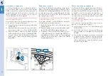
Page 23: ...2 2 1 6 7 8 9 10 5 4 3 2 12 11 1 13 1 16 Targhette Data plates Etiquetas ...

Page 24: ...e 6 Air bag maintenance plate Child seat warning plate 7 Airbag plate 8 Battery master switch instruction plate 9 Lead free petrol plate 10 Tyre pressure plate 11 Presence of tyre pressure control system plate 12 Engine and gearbox oil plate Engine oil level plate 13 Airbag system plate 1 Etiqueta homologación faros de cruce 2 Etiqueta del color de la pintura 3 Etiqueta Anticongelante 4 Etiqueta A...

Page 25: ...52 91 in Carreggiata anteriore Front track 1688 mm Vía anterior 66 45 in Carreggiata posteriore Rear track 1641 mm Vía posterior 64 60 in Peso in ordine di marcia Kerb weight Peso en orden de marcha cambio comando manuale manual control gearbox cambio accionamiento manual 1850 kg 4078 5 lb cambio F1 F1 gearbox Cambio F1 1865 kg 4111 5 lb Vettura a carico statico Vehicle under static load Automóvil...

Page 26: ...máx Dir 1999 99 CE Regime corrispondente giri min Max power engine speed rpm 7 250 Régimen correspondiente r p m Coppia massima Dir 1999 99 CE Maximum torque Dir 1999 99 CE Nm 589 Par máximo Dir 1999 99 CE Regime corrispondente giri min Corresponding engine speed rpm 5 250 Régimen correspondiente r p m Prestazioni Cambio Da 0 a 100 km h Da 0 a 400 m Da 0 a 1000 m Da 0 a 200 km h Transmission From ...

Page 27: ... del cambio 1 41 13 3 154 2 37 17 2 176 3 36 23 1 565 4 32 27 1 185 5 29 31 0 935 6 25 33 0 757 R 31 13 2 384 Impianto elettrico Tensione di alimentazione Supply voltage Tensión de alimentación 12 V Batteria Battery Batería FIAMM 12V 100 Ah 850A Generatore elettrico Alternator Generador eléctrico NIPPONDENSO 150 A Motorino avviamento Starter motor Motor de arranque NIPPONDENSO CO2 emissions g km C...

Page 28: ...ONE RE 050 Run flat 245 45 ZR18 285 40 ZR19 2 2 bar 32 psi 2 2 bar 32 psi BRIDGESTONE RE 050 Run flat 245 45 ZR19 2 2 bar 32 psi Pneumatici da Neve Snow tyres Neumáticos de nieve Velocità Max 240 km h Max speed 240 km h 149 mph Velocidad máx 240 km h PIRELLI Winter Sotto Zero 245 45 R18 285 40 R19 2 2 bar 32 psi 2 2 bar 32 psi Sostituzione Ruota Wheel Replacement Cambio de la Rueda Pre serraggio c...

Page 29: ...receives the punctured tyre information from the tyre pressure ECU it manages the residual tyre life by viewing a warning signal in the relativeareaontheTFTdisplayafter50km 31miles After having run 100 km 62 miles a message on the display will warn the driver not to drive further Always comply with the prescribed set up values as this is fundamentaltoobtainthebestperformancefromyourtyres and to en...

Page 30: ...ondiciones de utilización CAMBIO E DIFFERENZIALE compreso tubazioni GEARBOX AND DIFFERENTIAL including lines CAMBIO Y DIFFERENCIAL tuberías incluidas IMPIANTO CAMBIO F1 F1 GEARBOX SYSTEM SISTEMA CAMBIO F1 IMPIANTO FRENI E FRIZIONE BRAKE AND CLUTCH SYSTEM SISTEMA DE FRENOS Y EMBRAGUE Quantità Quantity Cantidad 13 l 1 5 l 1 0 2 0 l 1 000 km 5 0 l 1 0 l 1 3 l Rifornire con Fill with Rellenar con Shel...

Page 31: ... 50 IMPIANTO GUIDA IDRAULICA HYDRAULIC STEERING SYSTEM SISTEMA DE DIRECCIÓN ASISTIDA HIDRÁULICA Scatola guida Steering box Caja de dirección SERBATOIO CARBURANTE FUEL TANK DEPÓSITO DE COMBUSTIBLE Riserva Reserve Reserva Quantità Quantity Cantidad 1 3 l 19 0 l 1 8 l 100 g 105 0 l 20 0 l Rifornire con Fill with Rellenar con Shell DONAX UB BRAKE FLUID DOT4 Ultra GLYCOSHELL Shell DONAX TX Shell RETINA...

Page 32: ...tità Quantity Cantidad 265 cc 1100 30 g 6 5 l Rifornire con Fill with Rellenar con DELPHI RL 488 R 134 A Nota per la pulizia del parabrezza usare una fiala di glass cleaner in estate e due in inverno N B for cleaning the windscreen use one phial of glass cleaner in the summer and two in the winter Nota utilice para la limpieza del parabrisas un frasco de limpiacristales en verano y dos en invierno...

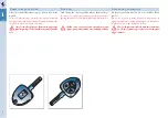
Page 33: ...3 2 1 1 26 ...

Page 34: ..._ 2 51 Salida y conducción del automóvil Cambio manual ________________________ 2 67 Durante la marcha ______________________ 2 69 Parada _________________________________ 2 70 Conducción segura ______________________ 2 71 Respeto por el medio ambiente ___________ 2 78 Palanca del freno de mano _______________ 2 81 Asientos delanteros ____________________ 2 82 Asientos Traseros ___________________...

Page 35: ...3 4 2 22 21 19 5 16 2 14 15 13 24 7 4 10 6 3 25 8 17 18 1 24 11 12 9 19 22 23 20 2 2 Plancia strumenti e comandi Instrument Panel and controls Salpicadero de instrumentación y mandos ...

Page 36: ... Handbrake lever 13 Air conditioning heating system controls 14 Fuel tank cap flap opening button 15 Luggage compartment lid opening button 16 Engine compartment lid opening lever 17 Central air conditioning and heating vents 18 Car stereo system 19 Passenger s power window control 20 Rear A C heating vent 21 Driver side power window controls 22 Internal door opening handle 23 Seat tilt lever 24 A...

Page 37: ...lizzazione marcia inserita 5 Spie di controllo Instrument panel 1 TFT Display 2 Electronic speedometer 3 Rev Counter 4 Gear engaged display 5 Warning lights Cuadro de instrumentos 1 Pantalla TFT 2 Tacómetro electrónico 3 Cuentarrevoluciones 4 Visualización de la velocidad engranada 5 Testigos de control ...

Page 38: ...rey background night black background To modify the display brightness refer to page 46 The user can interact with the system by choosing the graphic configuration and setting the parameters Three areas are identifiable on the screen on the basis of the display type chosen A permanent display of information shared by all configurations B display of the information generated by specific events and ...

Page 39: ... de la vista se producen conlapresiónejercidasobrelasteclas MODE DISP UP DOWN y ENTER situadas en el volante Description of CONTROLS MODE Brief pressure 2 sec Activates the MENU page Within a submenu returns to previous screen Odometer flashing resets to previous data display During an error message display cycle exits the cur rent display ESCAPE function Long pressure 2 sec MENU page not active a...

Page 40: ...metro parpadeante selección del TRIP a poner a cero Función Auto sensor crepuscular activa regulación de la intensidad luminosa de modo creciente DOWN selección de las funciones principales con desplaza miento hacia bajo Página MENÚ inactiva regulación de la intensidad luminosa del cuadro de modo decreciente Odómetro parpadeante selección del TRIP a poner a cero Función Auto sensor crepuscular act...

Page 41: ...using the MODE button see page 38 COMFORT TYRE PRESSURE TRIP A TRIP B Configuraciones La pantalla puede asumir las configuraciones siguien tes seleccionables tanto con la tecla DISP como des de la PÁGINA MENÚ con la ayuda de la tecla MODE véase pág 38 CONFORT PRESIÓN DE NEUMÁTICOS TRIP A TRIP B Comfort The display shows as well as the normal parameters the virtual control gauges such as oil temper...

Page 42: ... Trip A and B Unlike on the previous screens the level gauges are notdisplayed asthesearereplacedwith distancetrav elled average speed trip time and date N B Whenamalfunctionindicatorlamporawarn ing appears the TRIP configuration is dis played Trip A y B Respecto a las vistas anteriores no se visualizan los in dicadores de control sustituidos por Distancia reco rrida velocidad media tiempo de viaj...

Page 43: ... A auto maticallyresets whereasifitisenabled theactiveodom eter flashes use the UP and DOWN buttons to select the desired TRIP and press ENTER to reset the flash ing display When the odometer is flashing pressing the MODE button briefly or after 10 seconds returns to the pre vious screen Parámetroscomunesatodaslasconfiguraciones A Cuentakilómetros Presente en la pantalla TFT pulsando el botón EN T...

Page 44: ... la hora está presente siempre en to das las configuraciones y puede visualizarse en forma to 12 o 24 horas véase la pág 46 E Engine oil pressure gauge Under normal conditions the red warning light F switches on prior to start up to perform a self check If a failure occurs it lights up when the engine is run ning and pressure is insufficient In this case turn the engine off immediately and carry o...

Page 45: ...tor y diríjase a la RED DE ASISTENCIA FERRARI L Indicador de temperatura del agua Indica la temperatura del líquido de refrigeración Si se enciende el testigo de color rojo M indica una temperatura demasiado elevada Se enciende cuando la temperatura supera los 120 C En este caso reduzca inmediatamente el régimen de giro del motor si dicha temperatura persiste apague el motor y diríjase a la RED DE...

Page 46: ...s configurations from the MENU PAGE menu Page To display the MENU page press the MODE button briefly The following parameters can be set Lighting Display setting Date and time Language and units of measurement Car setting To select the above parameters and functions use the UP and DOWN buttons To confirm the selection press the ENTER button Implementación de las configuraciones Es posible implemen...

Page 47: ...ate can be displayed in two formats day month year or month day year To select the format and ad justitusetheUPandDOWNbuttonsandconfirmwith ENTER On the basis of the displayed format the range is from 1 to 12 or 0 to 23 To select the format and adjust it use the UP and DOWN button and confirm with ENTER Language and units of measurement The following language options are available English German I...

Page 48: ...or unlock Buzzer volume Light sensor TheparameterscanbeselectedwiththeUPandDOWN buttons To confirm the selection press the ENTER button If the Scheduled Maintenance option is selected the service time schedule is displayed see page 281 Configuración del automóvil Los parámetros modificables son Bloqueo de puertas Desbloqueo de puertas Volumen del zumbador Sensor de luz La selección de los parámetr...

Page 49: ...external temperature is not displayed it is also given on the TFT display Rev Counter It indicates the engine s r p m Avoid engine speed rates in the red sector If such speed rates are exceeded the ignition injection ECU will temporarily cut off the fuel supply Tacómetro electrónico Indica la velocidad de circulación Siempre que no se visualiza la temperatura exterior el valor se muestra también e...

Page 50: ... 4 4th gear 5 5th gear 6 6th gear d Automatic gearshifting mode When the symbol is displayed it indicates a failure in the gearbox Contact the FERRARI SERVICE NETWORK to have it checked Warning lights display If a warning light indicating a failure switches on while the vehicle is running contact the FERRARI SERVICE NETWORK to have the necessary checks performed Indicadordevelocidadengranada cambi...

Page 51: ...antalla ABS x WhiledrivingtoindicateamalfunctionintheABS system The standard brake system remains functional con tact the FERRARI SERVICE NETWORK ABS x Para señalar durante la marcha la ineficacia del sistema ABS El sistema normal de frenos permanece operativo diríjase a la RED DE ASISTENCIA FERRARI Brake failure x This indicates an insufficient level of brake fluid in the tank Simultaneouslightin...

Page 52: ...apague inmediatamente el motor y diríjase a la RED DE ASIS TENCIA FERRARI Temperaturadellíquidorefrigeración x Indica una temperatura demasiado elevada del líquido de refrigeración En este caso apague el motor y diríjase lo antes posi ble a la RED DE ASISTENCIA FERRARI Avería del cambio F1 x Fijo con señal acústica cuando se detecta un error de funcionamiento del cambio F1 Si la avería lo permite ...

Page 53: ...ol system and in the ignition in jection system After turning the ignition key to position II this remains lit for a few seconds following engine start up for a self check For further information see page 192 Anomalías del sistema de control del motor x Durante el funcionamiento para señalar una ano malía en el sistema de control de las emisiones y en el sistema de encendido inyección Permanece en...

Page 54: ...rrespondiente véasepág 136 Avería sistema CST El encendido del grafismo de color ámbar indica una avería del sistema CST véase pág 208 CST system fault When the amber icon turns on the CST system is signalling a fault see page 208 The Ferrari CODE system x The vehicle is equipped with an electronic sys temforimmobilizingtheengine FerrariCODE which activates automatically when the ignition key is e...

Page 55: ... CST x Cuando se produce el encendido simultáneo de los testigos indicados en la figura Atención riesgo de bloqueo de las ruedas posteriores a causa de la ineficacia del co rrector electrónico de frenada y la posi bilidad de acabar cruzándose Detenga el automóvil evitando frenadas violentas No prosiga la marcha y diríjase inmediatamente a la RED DE ASISTENCIA FE RRARI No obstante es posible mover ...

Page 56: ... Se enciende en caso que falle la instalación o se funda una de las lámparas de las luces de posi ción intermitentes o antiniebla posterior Nivel insuficiente del lavaparabrisas Señala un nivel insuficiente del líquido en el de pósito lavaparabrisas Interruptor inercial Señala la intervención del interruptor inercial en caso de accidente y la consiguiente ausencia de alimentación de combustible Ca...

Page 57: ...RI para com probar el automóvil Tapa de combustible abierta Indica que se ha abierto la tapa de combustible Avería de la dirección asistida Indica la ineficacia del sistema de dirección asis tida Diríjase a la RED DE ASISTENCIA FERRARI Avería de luces de freno Se enciende en caso que falle la instalación o se funda una de las lámparas de las luces de FRE NO Temperatura de los catalizadores En caso...

Page 58: ...mperatura exterior es igual o inferior a 3 C para señalar el riesgo de firme helado en la carretera En estas situaciones deberá adoptar una conduc ta prudente al volante y reducir la velocidad ya que la adherencia de los neumáticos se reduce notablemente En esta situación no conecte el modo SPORT Avería de los sensores de aparcamiento Indica la avería del sistema de sensores de apar camiento paral...

Page 59: ... are ei ther approaching or due on that day see page 281 Uponreachingadeadline contacttheFERRARI SERV ICE NETWORK Programa de Mantenimiento En función del mensaje combinado se señala la aproximación y el cumplimiento de la condición paraelmantenimientoprogramado véaselapág 281 Cuando se cumpla diríjase a la RED DE ASISTENCIA FERRARI Finger trap prevention system failure This indicates that the win...

Page 60: ... excessively high speeds Rodaje el estilo de conducción que se adopta durante los pri meros 1000 km de recorrido determina la finalización adecuada del rodaje evite por tanto permitir que el motor alcance regímenes elevados Motor y transmisión Durante los primeros 1000 Km de recorrido evite su perar las 5000 rpm Despuésdelencendido evitesuperarlas4000rpmantes de que el motor alcance suficiente tem...

Page 61: ...able to carry out these checks at least every 1000 km 620 mi and to always comply with the compulsory measures prescribed in the service time schedule It is also advisable to cleantheglassontheexternallightandallotherglass surfaces properly adjust the mirrors steering wheel seats and seat belts Capacities Use unleaded fuel only The use of fuel containingleadwouldirreparablydam age the catalytic co...

Page 62: ...n the door is closed the window automatically rise back to the up per limit position B upper threshold Condiciones En fase de apertura cierre de la puerta la ventanilla desciende automáticamente unos 2 centímetros posi ción A límite para evitar interferencias con la junta de la puerta Al cerrar la puerta la ventanilla alcanza automáticamente hasta el límite superior posiciónB cierre superior Openi...

Page 63: ...LOCK button E Using the handle F to open the door the window will lower to the preset limit When the door is closed it will rise back to the upper threshold position If the handle F is operated without opening the door the window will lower to the preset level but after 2 seconds if the door is not opened the window will rise to the upper threshold Therefore thehandlemustbereleasedandpulledagain i...

Page 64: ...uipped with a lamp G located beneath theinternalpanel whichindicatesthatthedoorisopen and illuminates the ground on which the driver or pas senger will step when exiting the vehicle For this pur pose the vehicle is also equipped with a second lamp H located beneath the external rear view mirrors Indicación de puertas abiertas e iluminación el área de salida del automóvil Cada puerta dispone de un ...

Page 65: ... halts at the end of its travel or when the button is pressed a second time The driver side is also equipped with button B which operates the passenger side power window Elevalunas del conductor Pulsando el botón A se activa el ascenso o descenso de la ventanilla Es posible el funcionamiento manual apertura cierreparcial oautomático apertura cie rrecompleto LapresiónsobreelbotónAporuntiem po breve...

Page 66: ...ththeupper weather strip when closed Press button D on the key for a long time to lower both windows Improper use of power window controls can be dangerous Before use always check that people and objects are at a safe dis tance Pay particular attention during the au tomaticoperationofthedriver ssidepow er window To protect against accidental operation of the powerwindowsthepassengersremaininginthe...

Page 67: ... of the external lights ac cording to the external brightness level The warning light on the dashboard switches on see page 52 Conmutador de luces El conmutador A tiene cinco posiciones 0 Luces apagadas 6 6 6 6 6 Luces de posición y de la matrícula encendidas 2 2 2 2 2 Luces de cruce encendidas F F F F F Luces de estacionamiento AUT Encendido y apagado automático de las luces exteriores en función...

Page 68: ...again to switchoffthehighbeamsandswitchonthelowbeams For the use of the high beams follow current Road Regula tions Luces de carretera Paraconectarlaslucesdecarretera conelconmutador de lucesA en posición 2 empuje la palanca izquierda B hacia el salpicadero Cuando las luces de carretera están encendidas se en ciende el correspondiente testigo en el cuadro de ins trumentos véase pág 52 Tirando nuev...

Page 69: ...idas se enciende en el cuadro de instrumentos el testigo co rrespondiente véase pág 52 Con las luces de aparcamiento conectadas bajando la palanca izquierda B véase pág 67 se encienden las luces de posición del lado izquierdo mientras que su biéndola se encienden las del derecho únicamente Automatic on and off When the light switch A is turned to AUTand the igni tion key is in position II the posi...

Page 70: ...igentes en el país por donde se circula recae siempre sobre el conduc tor El sistema de encendido y apagado automá ticodelaslucesexterioresdebeconsiderarsecomo una ayuda para el conductor Si es necesario encienda y apague las luces manualmente Twilight sensor The twilight sensor is composed of two sensors a glo bal sensor which measures the brightness upwards and a directional one which measures t...

Page 71: ...de reposo se rea liza automáticamente al realinear la dirección Para señalar un cambio momentáneo de carril que requie re un giro de volante mínimo se puede empujar la palanca sin llegar al bloqueo posición inestable Direction indicators With lever B in position up the right hand direction indicators are switched on down theleft handdirectionindicatorsareswitched on Warning light C will light up o...

Page 72: ...rabrisas solamente fun cionan con la llave de encendido en la posición II Windscreen wipers The lever A has 5 settings OFF Windscreen wipers stationary AUTO Automatic operation In this position the rain sensor sensing range can be adjusted lever pushed down to first click position 1 Slow continuous operation lever pushed down to second click position 2 Fastcontinuousoperation leverpusheddown to th...

Page 73: ...le while Do not start the windscreen washer during the cold months until the windscreen has warmed up If it has not warmed up the liquid could freeze on the glass and block the view Lavaparabrisas Se acciona tirando de la palanca A hacia el volante re torno automático Accionando el lavaparabrisas entra automáticamente en funcionamiento el limpiaparabrisas Soltando la palanca el lavaparabrisas deja...

Page 74: ...dry to wiper at second continuous speed with pouring rain To regulate the frequency of intermittent operation with the lever on the AUTO position turn the dial C Turningthedialclockwise intermittentoperationvar ies from a maximum fast intermittent wipe to a min imum slow intermittent wipe N B The rain sensor function is reset by turning the igni tion key to position 0 and also by leaving the right...

Page 75: ... automático En caso de presencia de hielo o nieve sobre el parabrisas delantero no active el sensor de lluvia para evitar que se dañe el motor del limpiaparabrisas y o las escobillas Beforecleaningthefrontwindscreen for exampleinservicestations makesurethe rain sensor is switched off or that the key is turned to 0 The rain sensor must be switched off also when washing the car by hand or in automat...

Page 76: ...the horn symbol A on either side of the steering wheel SPORT mode The driver can change the vehicle setting depending on his her own driving style The SPORT mode can be activated or deactivated bypressingbuttonB Activationisindicatedbywarn ing light C on the instrument panel The SPORT mode function will favour a racing style drivingunderhighgripconditions whilethe normal mode will favour a comfort...

Page 77: ...indicated on the TFT display by the green warning light F for a minimum time of 4 seconds In medium or low grip conditions wet icy or sandy roadbeds etc keep the CST system switched on and do not select the SPORT mode Inanycase weadviseyoutokeepthe CSTsystemactivated even under normal driving conditions When the CST is active the amber warn ing light switches on to indicate a systems malfunction C...

Page 78: ...T display buttons The MODE DISP UP DOWN and ENTER but tons enable interaction with the TFT display system and their operation is described in the TFT display paragraph see page 38 Only make changes to the TFT display with the car stationary Botones de la pantalla TFT Los botones MODE DISP y UP DOWN y EN TER sirvenparacomunicarseconelsistemadelapan tallaTFT cuyafunciónsedescribeenelapartado pan tal...

Page 79: ...n sens ing system When this function is deactivated the led above the button will flash for 3 seconds and then turn off Deactivation of anti lift alarm system Pressing button B deactivates the anti lift alarm sys tem When this function is deactivated the led above the button will flash for 3 seconds and then turn off Mandos en el techo Desconexión de sensores volumétricos del sistema de alarma Pul...

Page 80: ...procedure with the vehicle in motion The detected situation will then be shown on the dis play For further information refer to the Tyre pressure monitoring system on page 227 Handsfree microphone optional The microphone D is available on cars equipped with a phone supplied on request For further information on the device refer to the Carrozzeria Scaglietti us er s manual Botón de calibrado de la ...

Page 81: ...ton again When the lights are switched on the direction indica tors the relative warning lights on the instrument pan el and the button itself all flash Door lock engagement and release The buttons B and C located on the central tunnel operate respectively the doors locking and release functions see page 62 Opening the glove compartment ButtonDcontrolstheglovecompartmentopening see page 142 Mandos...

Page 82: ...en una de las posi ciones siguientes Posición 0 Stop Motor apagado se puede extraer la llave Bloqueo de dirección conectado Se pueden encender las luces de emergencia y las de estacionamiento Para facilitar el desbloqueo de la dirección mientras gira la llave gire también ligeramente el volante en ambos sentidos Ignition switch The ignition key can be set to the following positions Position 0 Stop...

Page 83: ...er starting up the Check OK indicator will light up Position III Ignition Never remove the key when the car is in motion The steering wheel will lock with the first steer ing turn Alwaysremembertoremovethekeyfrom the ignition block when you get out of the vehicle Never leave children unattended in the car In case of tampering with the device con tact the appropriate authorities for in spection Pos...

Page 84: ... few seconds The gear currently engaged will remain highlighted on the display When the door on the driver s side is opened the F1 sys tempumpstartsupforseveralseconds Thisfunctionmakes it possible to have the system ready when the ignition key is inserted The failure warning light B may also flash for a short time 10 sec and then switch off the system is completing the start up stage and will the...

Page 85: ... ignition key was turned to position II Contact the FERRARI SERVICE NETWORK to have the mal function identified and repaired Si el testigo B continúa parpadeando sin apagarse repita el encendido del sistema después de haberlo apagado Si la anomalía persiste diríjase a un CENTRO AUTORIZADO FE RRARI para que se realice las comprobaciones pertinentes Si el testigo B permanece encendido el sistema est...

Page 86: ...ring wheel R Reverse gear lift and pull the lever D in the direction of the rear of the car Keep lever D pulled up until the R sig nal appears on the display Toengagethereversegearwiththereversegear shift lever D keep it pushed forwards until the 1 signal appears on the display Engagement of the 1st gear push lever D forwards Upshifting pull the UP lever towards the steering wheel Downshifting pul...

Page 87: ...stema con el motor apagado para evitar des cargar la batería Evite toda secuencia innecesaria de cambio con el motor apagado para impedir un calentamiento excesivo de la bomba del sistema F1 Starting the engine Before starting up the engine make sure that the alarm system and all electrical devices with a high power absorption are off Ensure that the handbrake is engaged and that the doors are clo...

Page 88: ...s thisstepcouldtakeaslightly longer time However if the gearshift is in neutral N the start up is immediate With the engine started release the key which will automatically return to position II If the engine fails to start after turning the key back to the 0 position wait until the gearshift display switches off and then repeat the entire procedure After several attempts if the engine fails to st...

Page 89: ...r directamente de la 1ª o 2ª velocidad a la R marcha atrás accionando la palanca C y de la marcha atrás a la 1ª empujando hacia adelante la pa lanca D véase pág 85 o tirando hacia el volante de la palanca UP Si se introduce la marcha atrás se conecta también una se ñalacústicadeseguridadquesuenaintermitentementetodo el tiempo que se encuentre engranada la marcha R Si en el paso R 1ª el sistema eng...

Page 90: ...ut pressing the brake pedal or the accelerator the engine compartment lid is opened The acoustic alarm may also come on to forewarnthedriverthattheclutchisstart ing to overheat This may occur when using the accelerator pedal with the car stopped on up hill stretches or during the pickup manoeu vre In these cases it is necessary to release the accelerator pedal and use only the brake pedal to keep ...

Page 91: ...ed and with the brake pedal pressed Ifthecarisstoppedonanuphillstretch donotusethe pick up manoeuvre to keep the car stationary Use the brake only and press the accelerator pedal only when ready to depart If the accelerator pedal is pressed very quickly fully down with the CST cut out and the SPORT but ton activated there will be a performance start off which will involve marked skidding of the dr...

Page 92: ... pressed all the way down and with the engine running at over 5500 rpm In any case it is best to Shift gears without releasing the accelerator pedal if it is pressed Wait until one gearshift is completed before request ing the next one thereby avoiding a rapid sequence of multiple requests CAMBIO DE MARCHA HACIA ARRIBA UP Actúe sobre la palanca derecha UP sin soltar el pedal del acelerador La soli...

Page 93: ...t until a gearshift has been completed before re questing another one avoiding multiple requests in rapid sequence CAMBIO MARCHA EN REDUCCIÓN DOWN Actúe sobre la palanca izquierda DOWN sin soltar tampoco el pedal del acelerador La solicitud de DOWN no se aceptará cuando la so licitud de marcha obligue al motor a trabajar más allá de un cierto régimen de giro en función de la marcha solicitada o si...

Page 94: ...again Parada del automóvil Cuando el automóvil se detiene el sistema introduce automáticamente la 1ª velocidad salvo si se ha solici tado anteriormente la N Con el automóvil aparado y el motor en marcha man tenga pisado el pedal del freno hasta que decida partir Apagado del motor y del sistema Se puede apagar el motor tanto con el cambio en N como con una velocidad engranada Después de haber girad...

Page 95: ...o solicite la inserción de una marcha mientras el sistema se está desconectando Otras funciones del sistema Modo Baja Adherencia Se puede utilizar cuando el firme de la carretera se presente especialmente deslizante nieve hielo y se activa odesactiva pulsandoelinterruptorE Estohace queseenciendaeltestigo Fcorrespondienteenlapan talla TFT del cuadro de instrumentos El sistema inserta automáticament...

Page 96: ...SPORT operationmodesbefore selecting the Low grip mode Automatic gearshift mode This mode is activated or deactivated using the G switch The symbol d auto H will light up on the engaged gear display on the dashboard and the sys tem will automatically shift the gears UP and DOWN according to the speed of the vehicle to the engine speed rate and to the torque power requested by the driver The Automa...

Page 97: ...c to the Normal mode It is a good rule to deactivate other operation modes before selecting the Automatic mode auto H yelsistemafuncionaráenmodo CambioAuto mático manteniendo no obstante las suspensiones en la posición SPORT Es posible volver al modo normal o SPORT si éste era el modo activo anteriormente realizando un cambio de marcha o manteniendo pulsado el interrup tor Ghasta que se apague el ...

Page 98: ...though the respec tive indicator will light up The SPORT mode is characterized by a stiffening of the suspensions and faster gearshifting compared to the Normal mode Furthermore in this mode the intervention of the CST system is much more noticeable and when the vehicle accelerates suddenly the vehicle s grip on the road is much lower Gearshifting will be faster if requested with the ac celerator ...

Page 99: ...e tracks Incaseoffaultsinthecontrolleverassemblies thesystem as wellasactivatingthebuzzerandturningonthefaultwarn inglight B seepage83 auto selectsthe Automatic mode and any further gearshift commands will be ignored in cluding N and R If the malfunctioning persists contact the FERRARI SERVICE NETWORK as soon as possible to have the cause eliminated Los cambios de marcha DOWN sin pisar el pedal de...

Page 100: ...isplay Turn the key to position III and release it as soon as the engine starts Do not keep the key turned to position III for a long time If the car fails to start turn the key back to the position 0 before repeating the procedure After the engine has been started the words Check OK will appear If the Check OK symbol does not appear turn the key back to position 0 wait a few seconds and then repe...

Page 101: ...tick into the 1st gear position Use the 1st gear for parking and for hill starts Completely release the handbrake Slowly release the clutch pedal while gradually ac celerating Then proceed to engage the other gears pushing the clutch pedal all the way down and moving the gear stick into the next position When shifting to a lower gear take care not to exceed the peak engine speed red zone allowed f...

Page 102: ... malfunction in the respective system Ensure proper operation of the various devices by checking the respective control instruments Continuing to drive with a red warning lightswitchedoncouldputtheoccupants safety at risk and cause serious damage to the vehicle affecting its operation and perform ance After racing type driving let the engine idle for several minutes before stopping it in order to ...

Page 103: ...harp downhill slopes use a wedge or rock to block the wheels Never leave the ignition key in position II Always remove the key when getting out of the car Never leave children unattended in the car Do not park the car on flammable mate rials paper grass dry leaves etc They could catch fire if they come into contact with hot parts of the exhaust system Do not leave the engine running with the car u...

Page 104: ...nsure that nothing mat covers etc is blocking the pedals Ensure that lights and headlights are working prop erly Ensurethatanychildrestraintsystems childcarseats etc are secured onto the rear seat correctly Topreventobjectsbeingthrownforwardsintheevent of sudden braking place them in the luggage com partment Your reflexes are quicker if you eat lightly before driving avoid heavy meals before a tri...

Page 105: ...edriverandforoth ers Travellingwithoutyourseatbeltfastened increases the risk of serious injury and death in the event of a collision Always make sure the seat belts are fastened This applies to those travelling in the front or the rear includ ing the children in their car seats Deactivate the passenger s airbag where possible if a children s car seat is fitted on the front seat Do not travel with...

Page 106: ...ante del aire del ha bitáculo No descienda nunca pendientes con el motor apaga do En estas situaciones se carece de la ayuda del fre no motor del servofreno y de la dirección asistida la frenada puede requerir un mayor esfuerzo sobre el pedal y girar un mayor esfuerzo sobre el volante Driving at night When you are travelling at night follow these funda mental rules Reduceyourspeed particularlyonro...

Page 107: ... the other vehicles and reduce your speed When it is raining particularly hard visibility can also be reduced In these cases to make yourself more visible to others switch on the low beams even dur ing the day Do not drive though puddles at high speeds as you donotknowhowdeeptheymaybe travellingthough a puddle at high speeds can result in loss of vehicle control aquaplaning Hold the steering wheel...

Page 108: ...s could cause problems for the occu pants of the vehicles behind you Remember that fog makes the roadbed damp and thereforeallmanoeuvresaremoredifficult and what is more braking distances become longer Keep a safe distance from the vehicle in front of you Avoidsuddenchangesinspeedanddirection asmuch as possible As far as possible avoid overtaking In the event of an emergency stop failures inabilit...

Page 109: ...ción en carreteras de montaña Para no sobrecalentar los frenos en los descensos utilice el freno motor introduciendo velocidades cortas No realice los descensos en ningún caso con el motor apagado o en punto muerto ni mucho menos con la llave de contacto extraída de la cerradura de la co lumna de dirección Conduzca a velocidad moderada evitando cortar en las curvas Recuerde que los adelantamientos...

Page 110: ...metime compatiblywiththetyre sphysicallim its due to lateral grip When the ABS is activated during emergency brak ing or in low grip conditions the driver will feel a slight pulsing of the brake pedal Do not release the pedalbutcontinuetopressittogivecontinuitytothe braking action TheABSpreventsthewheelsfromlocking butitdoes notincreasethephysicalgriplimitsbetweenthetyres and the road keep a safe ...

Page 111: ...abilidad de todos FERRARI ha diseñado y realizado este automóvil utili zandotecnologías materialesydispositivoscapacesde reducir al mínimo las influencias nocivas para el medio ambiente Es importante que mantenga siempre un comporta miento correcto y responsable durante la utilización del automóvil ya que evitará daños al medio ambien te Es importante mantener el automóvil en perfecto esta dosigui...

Page 112: ...ping these devices in good working conditions is the first rule for driving ecologically sound The first precaution is to follow the Service Time Schedule scrupulously If starting is difficult do not make prolonged attempts Pushstarts towingthevehicleorusingdownhillslopes to start are all manoeuvres which could damage the catalytic converters Use the battery charger only and contact the FERRARI SE...

Page 113: ...Never spray anything on the catalytic converters the lambda sensors or the ex haust lines It is normal for the catalytic converter to reach extremely high temperatures dur ing operation To avoid fire risks do not park the car on flammable materials grass dry leaves pineneedles etc Failuretoobservethese rules may create risk of fire No instale otras protecciones térmicas ni retire las existentes en...

Page 114: ...handbrake pull the lever slightly up wards and press the release button C Lower down the lever fully keeping the button pressed The warning light B will switch off when the hand brake is fully released Always use the handbrake when the car is parked After hearing a series of catches released by pullingthehandbrakelever thevehicleshould be blocked If this is not the case please contact the FERRARI ...

Page 115: ...thecarisstop ped The seats can only be adjusted with the ignition key in position II It is however possible when the door is closed to op erate the seat for approx 15 seconds after turning the ignition key to 0 and then for other 15 seconds after the last operation 1 Back forwards adjustment Push lever A on the outer side of the seat forward or back 2 Height adjustment Move the rear part of the le...

Page 116: ...re the user can pro duce a combined motion which allows the adjustment of both the seat height and tilt position at the same time 5 Seat back rake adjustment Push lever B forwards or backwards to raise or lower the seat backrest respectively 6 Adjusting the headrest Move the lever B up or downwards until the headrest is positioned correctly at the nape of the neck The upper seatbelt coupling moves...

Page 117: ... device operative with doors open only which moves the said seats forwards and lowers them automatically when their seatbacks are lowered and returns them to the original position when the seatbacks are raised again Regulación lumbar Pulse el mando C a la altura de las flechas horizontales para incrementar o reducir el apoyo lumbar y a la altu ra de las verticales para subir o bajar el apoyo lumba...

Page 118: ... and position the exter nal rear view mirrors once again to ensure you have the best possible visibility for performing the manoeu vre then disengage the reverse gear Next push one of the three buttons F each one corre spondingtoamemorisableposition for3secondsuntil you hear a double confirmation tone Lumbar support adjustment is not included in the seat position memorisation The memorisation of a...

Page 119: ...e hasta la señal acústica de finalización del asiento Para detener el asiento pulsar uno de los botones F o uno de los mandos para la regulación véase la pág 114 Un funcionamiento incorrecto de la centralita de control de los asientos se indica con 5 señales acústicas emitidas suce sivamente al girar la llave de contacto a la posición 0 dirí jase en este caso a la RED DE ASISTENCIA FERRARI para el...

Page 120: ...ggiatesta posteriori B sono fissi Rear seats These can seat 2 passengers Armrest The rear armrest is mobile and can be folded up into the seat back To lower it pull the tab A Headrest The rear headrests B are fixed Asientos Traseros Permiten alojar 2 pasajeros Apoyabrazos El apoyabrazos trasero es móvil y se introduce en el respaldo Tire de la lengüeta A para bajarlo Reposacabezas Los reposacabeza...

Page 121: ...e control A in the four direc tions Thesteeringwheelpositionismemorised togetherwith the position of the external rear view mirrors when the driver s seat position is stored Do not adjust the steering wheel with the car moving To assist the driver when entering and exiting the ve hicle in these situations the steering wheel moves up automatically see Easy entry system on page 118 Regulación del vo...

Page 122: ...ear view mirror This can be adjusted manually For the anti dazzling effect move lever A forwards External rear view mirrors Thesecanbepoweradjustedusingthecontrol B with the ignition key in position II and are equipped with defogging elements Espejos retrovisores Espejo retrovisor interior Se orienta manualmente Para obtener el efecto antideslumbrante sitúe la pa lanca A hacia adelante Espejos ret...

Page 123: ...t being changed inadvertently 3 Closing mirrors by rotating selector switch B to the lower central position both mirrors close to facilitate parking in narrow spaces When the selector is re turned to the upper central position the mirrors re turn to the open position Do not turn the ignition key to position 0 while the rear viewmirrorsarebeingtilted whethertheyarebeingopened or closed If not the m...

Page 124: ...djust the position of the mirrors then engage the reverse gear and reposition the external mirrors to ensure the best possible visibility for manoeuvring then disen gage the reverse gear Lastly press one of the seat buttons 1 2 or 3 see page 117 eachoneofwhichcorrespondstoamemorisable position until a double confirmation tone is heard Thenewpositionoftheexternalrear viewmirrorswill be automaticall...

Page 125: ...ct ly fastened and positioned seat belts at all times Correct use of the seat belts can markedly re duce the risk of serious injury in the event of an accident Theseatbeltsareautomaticwiththreefasteningpoints and an emergency inertia locking system on the wind ing unit which is fitted with a pre tensioner For maximum protection keep the backrest in the up right position ensure that your back is pr...

Page 126: ...sk of injury in a collision substantially Thecorrectadjustmentisachievedwhenthebeltpasses about mid way between the end of the shoulder and the neck Using rear seat belts The belts for the rear seats must be worn as shown in the illustration Remember that in the event of a violent collision passengersintherearseatswho are not wearing seatbelts as well as risking se rious injuries also put the fron...

Page 127: ...d a little and then pull it again but do not jerk it roughly Make sure that it has clicked into the locked posi tion Position the seat belt correctly Ifthedriver sseatbelthasnotbeenfastened thewarn inglightEwillswitchonwhentheignitionkeyisturned to position II Do not use any objects spring clips locks etc that could keep a seat belt from fitting properly Do not allow children to be held on a pas s...

Page 128: ...ores El pretensor se activa en caso de colisión frontal vio lenta El cinturón se recoge un poco antes de iniciar la acción de retención garantizando de este modo una perfecta adhesión al cuerpo La activación de los pretensores se señala al encender se el testigo G en el cuadro de instrumentos y al blo quearse el cinturón Despuésdelaactivación elpretensorcesa sufuncionamientoynosepuedereparar Diríj...

Page 129: ...leach or aggressive solvents as they can weaken the fibres Make sure the retractors do not get wet they will operate properly only if they do not undergo water infiltration The pre tensioner requires no maintenance or lubri cation If immersed in water or mud the pre tension er must necessarily be replaced The pre tensioner must be replaced every 15 years All work on any part of the safety system c...

Page 130: ...d to protect persons weighing at least 36 Kg 79 lb and of heights exceeding 1 50 m 4 9 feet To hold any passengers who do not fall within these limits specialrestrainingsystems equippedwithspe cific belts must be fitted or accessories which can adapt the child s position to suit the vehicle s seat belts Follow the instructions that the Manufacturer of the devices is required to supply when install...

Page 131: ...pective restraining systems as in the event of a collision this is the safest place in the car Donotfastenrear facingbabyseatstothe passenger s seat if the airbag is active as the child risks serious injury if the airbag is in flated Backwards mountingchildseatsmustnot beusedonfrontpassengerseatsequipped with airbags as these could cause injury and even death during inflation even in minor col lis...

Page 132: ...lts or child re straintsystems Establishedlegislationin some countries already provides that children under12yearsofagemaynottravelinthefront passenger seat The sticker L prohibits placing a child s seat facing backwards Ifyouhavetocarryachild alwaysswitch off the passenger side airbag optional feature not provided on some models before placing the child seat on the passenger s seat Además el asie...

Page 133: ...inturones de seguridadperoincrementasuefectividad Un uso correcto de los cinturones de seguridad integradoconlaaccióndelosairbags ofrecela máxima protección en caso de colisión frontal Elementos del sistema de airbags El sistema de airbags está formado por dos cojines de inflado instantáneo situados uno A en el lado del con ductor en el centro del volante y el otro en el lado del acompañante en el...

Page 134: ...riverandpassengerarebothadvised not to travel handling objects beverage cans or bottles pipes etc that could cause in jury in the case of airbag activation When the system starts operating gases are released in the form of fumes together with the gas used for inflating the airbags These gases are not harmful Drive with your hands always on the frame of the steering wheel so that in the case of act...

Page 135: ...E NET WORK personnel All the airbag system components must be replaced after an accident that has caused airbag activation Followinganaccidentnotinvolvingairbagactivation you must contact the FERRARI SERVICE NETWORK to have the systemcheckedandreplaceanysystemcomponentsthatmay be damaged or malfunctioning Damaged or defective components of the airbag system cannot be repaired and must be replaced ...

Page 136: ...ed10years after installation even if the car has not been involved in any accidents The plate D on the right hand side of the dashboard bears the airbag system expiration date Please contact the FERRARI SERVICE NETWORK for replacement of the system when this date approaches The plates E and F indicate that the airbag system is installed Si el automóvil ha sido objeto de robo o de tentativa de robo...

Page 137: ... thedashboard Theswitchisaccessiblewithopendoor only The key switch has two positions 1 passenger airbag active position ON the corre sponding warning light on the instrument panel is off it is prohibited to carry children on the pas senger seat 2 passengerairbagdeactivated positionOFF warn ing light G on instrument panel and led H on roof pushbutton panel lit up children can travel in the passeng...

Page 138: ...rsideairbagiscutout because a person considered by the laws inforcetobeatriskistravellingandmustthere foreusesupplementaryrestrainingsystems the passenger will not have the additional protec tion of the airbag in the event of a collision Only deactivate the airbag when a per son at risk is being carried and always reactivate it at the end of the journey El testigo G y el led Hpermanecen encendidos...

Page 139: ...ents radio CD player CD holder aerial amplifier CD changer central twiddler speaker side twiddler speaker n 2 sidewooferspeaker n 2 rearlateraltweeters n 2 central woofer speaker sound system amplifier bassbox with speaker Underneath the radio CD player A there is a CD hold er which can be accessed by opening the flap B Radio reproductor de CDs El sistema radio reproductor de CDs incluye los si gu...

Page 140: ...ne drawer can be opened at a time To close the drawer lift the tilted end E and push the drawer C towards the dashboard Close the flap B pressing its upper central part The CD changer F is installed in the luggage compart ment The vehicle can be fitted with a GPS aerial and satellite navigation system For further information on this de vice refer to the Carrozzeria Scaglietti user s manu al Empuje...

Page 141: ...seconds whenthedoorsareunlocked forapprox 10seconds when the inertia switch is activated for approx 15 minutes Instead they switch off when the time set comes to an end on closing the doors and turning the key is in posi tion II on locking the doors when the inertia switch is rearmed Plafones Los plafones se encienden automáticamente en las situacio nes siguientes al abrirse una puerta durante uno...

Page 142: ...nzadello stesso punto Rear When the doors are closed the dome lights E located above the side quarter windows can be switched on by pressing the spot F to switch them off press the same spot Traseros Con las puertas cerradas los plafones E situados enci madelasventanillasfijaslateralessepuedenencender pulsando en el punto F para apagarlos pulse a la altu ra del mismo punto ...

Page 143: ...o access the document compartment A push the but ton B on the tunnel The compartment is lit by the lamp C which switches on automatically when the lid is opened Keep the document compartment closed when travelling To close the compartment push the upper end until you hear the click of the lateral locks Underneath the dashboard in position with the exter nal edge of the document compartment there i...

Page 144: ...re is a mesh pock et F to hold newspapers magazines etc Do not place metal items in these pockets as this could be dangerous for the passen gers in the event of a collision Clothes hooks They are fitted in the rear of the passenger compart ment Press button G to draw out the hook To refit the hook push it upwards into its seat Turn hooks to close position when not used Alojamiento portaobjetos En ...

Page 145: ...e key is inpositionII Afterreachingtherequiredtemperature the cigarette lighter is automatically snap released to its start position and is ready to be used Do not use the cigarette lighter seat as a power socket for electrical items of any kind The cigarette lighter reaches very high temper atures Handleitwithcaretoavoidriskofburns and fire Ceniceros delantero Para acceder al ceniceroH o al encen...

Page 146: ...abletoshadeboththewindscreenand the windows on the doors There is a mirror on the back of the passenger s sun visor P which can be accessed by lifting the cover Q Ateithersideofthemirrortherearetwocourtesylights R which switch on when the mirror cover Q is lifted Viseras parasol Se orientan hacia el parabrisas y hacia las ventanillas de las puertas Detrásdelaviseraparasoldelacompañantesedispone de...

Page 147: ...ocated in the centre of the front part of the vehicle The lid is kept in the open position by two gas struts C Always check to ensure that the lid is closed properly to prevent it from open ing while driving Capó motor Apertura Para desbloquear el capó motor tire de la palanca A situada debajo de la columna de dirección Libere la palanca B de retención del capó situada en posición central en la pa...

Page 148: ...su posición abierta con 2 amortiguadores B Abriendoelcapómaleteroseenciendeautomáticamen te el plafón C Apertura de emergencia Para abrir el capó del maletero también se puede utili zar la tecla presente en el mando a distancia véase la pág 9 En caso que el botón A no funcione tire de la palanca D situada en el hueco portaobjetos del apoyabrazos entre los asientos traseros Después de abrir manualm...

Page 149: ...ng If air is released when the cap is unscrewed this shouldbeconsideredperfectlynormal Thetankfillerneck s airtight seal can cause a slight pressure build up in the sys tem Always switch off the engine during refu elling Take extreme care when removing the cap When refilling the tank do not approach the vehicle with naked flames or lit cigarettes fur thermore inhaling vapours can be harmful Tapón ...

Page 150: ... to close it Ensure that the string D is not hanging out of the fuel filler cap compartment Cierre Apriete hasta el fondo el tapón B y cierre empujando la tapa Asegúrese de que el cable D no sobresale del hueco del tapón del depósito Emergency opening In the event of a failure of the button A the lid can be opened manually by pulling the small lever E located on the left hand side of the luggage c...

Page 151: ...earbox Thespecificdrivingandroadregulations must be followed when the car is being towed Do not hook the car through suspension levers and rims use only the tow hook in its seat Keep the ignition key in position II to permit the lights to work and to prevent thesteeringwheelfromlockingifturned donot start the engine when towing the vehicle Keep in mind that the power steering and brake servo will ...

Page 152: ...151 2 7 8 9 5 1 2 3 3 3 3 3 3 4 4 1 1 2 1 6 2 119 Climatizzazione Airconditioningandheatingsystem Climatización ...

Page 153: ...e temperature sensor 7 Passenger compartment temperature sensor 8 Heatingandventilation airconditioningcontrols 9 Pollen filter The vehicle is equipped with an automatic dual zone air conditioner heater This latter is special in that it adjusts the air tempera ture distribution and flow in the vehicle s passenger compartment in two separate zones driver s side and passenger side 1 Difusores fijos ...

Page 154: ...values to suit the passengers needs Controls A Left hand temperature setting B Air conditioning compressor activation deactiva tion C Left hand air distribution selection D Windscreen defogging demisting E Fan speed adjustment F Recirculation function G Right hand air distribution selection H Defogging demisting rear window and external rear view mirrors I Right hand temperature setting J Residual...

Page 155: ...lected temperature Pressed led on The air conditioner is off However heatingisstillenabledandwillturnon according to the temperature set Interruptor de accionamiento del acon dicionador B En reposo el acondicionador está conectado El aire se refrigera y o sólo se deshumidifica en función de la temperatura seleccionada Pulsado led encendido El acondicionador está desconectado La calefacción también...

Page 156: ...del aire se gestiona con un sistema electrónicoenfuncióndelascondicionesambien tales y de la temperatura seleccionada Manual Permite dirigir el flujo de aire en seis posiciones en la zona correspondiente conductor acompa ñante Mandos de selección de temperatura A y I Configura el valor de temperatura deseada en el interior del habitáculo En las posiciones extremas se encuentra la acti vación de la...

Page 157: ...ra activar esta función se tiene que empu jar el botón REST antes de girar la llave a 0 El sistema utilizará la bomba de recirculación del agua caliente y la primera velocidad del ventila dor para mantener la temperatura Air recirculation switch F Released The air flow comes from the outside Whenoutsidetemperaturesexceed35 C 95 F theairrecirculationoptionremainsonwitha120 secondpauseeverytwentymin...

Page 158: ...na sul valore desiderato si consiglia di non variare la posizione del commutatoreselezionetemperaturafinoaquandonon intervengonogrossevariazioninellatemperaturaester na Una variazione nella posizione del commutatore sele zione temperatura comporta una certa differenza tra la temperatura nell abitacolo e l aria in uscita dalle boc chette Questadifferenzaandràattenuandosimanmano che l impianto va a ...

Page 159: ...low B Air flow rate C Turned anti clockwise open Turned clockwise closed Maintenance The pollen filter must be replaced every year as indi cated in the Service time schedule Sun radiation sensor The sensor is positioned on the instrument panel and itoptimisesventilationandtemperaturecontrolinside the compartment depending upon the incidence an gle of the sun rays Regulación de los difusores orient...

Page 160: ..._________3 5 Engine lubrication system _________________3 7 Gas and oil vapour recirculation__________ 3 10 Cooling system __________________________ 3 12 Ignition Injection System ________________ 3 17 Fuel supply system _______________________ 3 21 Air injection system and catalytic converters ________________ 3 28 Exhaust system overheating alarm devices_ 3 32 Engine malfunction alarm devices__...

Page 161: ...160 3 3 2 Gruppo motore Engine assembly Grupo motor ...

Page 162: ...s 1 6 intake valves 2 Cam shaft drive pulley for cylinders 1 6 exhaust valves 3 Drive pul ley 4 Tensioner 5 Camshaft drive pulley for cylinders 7 12 intake valves 6 Camshaft drive pulley for cylinders 7 12 exhaust valves 7 Driving dowels Distribución Esquema accionamiento distribución 1 Polea del árbol de levas de accionamiento de las válvulas de admisión de los cilindros 1 6 2 Polea del árbol de ...

Page 163: ...ts with au tomatic clearance recovery which always ensure oper ating tolerance The timing is controlled by means of 2 timing belts controlled by the crankshaft On each head the valves are arranged in a 20 30 V layout with a bucket at the upper end that houses a pad La distribución es por 4 árboles en cabeza 2 por ban cada y 4 válvulas 2 de admisión y 2 de escape por cilindro accionadas por taqués ...

Page 164: ...zione Timing data Datos de fase Belts Each engine bank is equipped with a belt for camshaft control There are two additional belts on the engine which control the auxiliary parts one for the water pump and the hydraulic steering pump and another for the air conditioning system compressor and the power alter nator In normal operating conditions the belt tension does not require any adjustment The b...

Page 165: ...a compressore A C e alternatore Belts 1 Timing belts 2 Water pump and hydraulic steering driving belt 3 Alternator and A C compressor belt Correas 1 Correas de accionamiento de la distribución 2 Correa de accionamiento de la bomba de agua y de la bomba dirección hi dráulica 3 Correa del compresor del A A y del alternador ...

Page 166: ...ión del motor Lubrication system A Oil radiator B Oil tank C Oil filters D Oil pressure electric transmitter E Delivery pump F Scavenge pump Q Pressure relief valve H Blow by system I Thermal contact Sistema de lubricación A Radiador del aceite B Depósito de aceite C Filtros de aceite D Transmisor eléctrico de la presión de aceite E Bomba de alimentación F Bomba de recuperación G Válvula limita do...

Page 167: ... apagado se gira la llave de contacto a la posición II o cuando con el motor en marcha desciende por debajo del valor mínimo En condiciones normales de funcionamiento la pre sión de aceite debe estar comprendida entre 5 6 bar con el motor en marcha a 6000 rpm y temperatura de aceite de 100 C Un valor de presión comprendido entre 2 y 2 5 bar con motor caliente a ralentí también se considera normal ...

Page 168: ... dipstick which is located in front of the engine oil filler cap on the left of the engine compartment If following the check the oil proves to be under the MIN level top it up and then have the system checked by a FERRARI SERVICE CENTRE MAX MIN 1 5 litres Unscrew the tank cap and top up with the prescribed oil if necessary see Capacities section on page 29 taking care not to exceed the MAX level ...

Page 169: ...ur recirculation Recirculación de gases y vapores de aceite A Tubo de salida de vapores de aceite de lasculatas B VálvulaunidireccionalPCV C Depósito de aceite D Tubo de admi sión de vapores de aceite E Separador de vapores de aceite F Tubo de drenaje delaceite G Válvulasinretorno H Tubo de recuperación de vapores de aceite del colector A Head vapour outlet pipe B One way PCV valve C Oil tank D Oi...

Page 170: ...dos retorna al de pósito a través de un tubo de drenaje con válvula sin retorno otra parte de los vapores son aspirados por el motor a través del tubo de admisión de vapores gra cias a la depresión creada por el motor en condiciones normales de funcionamiento En caso de mal funcionamiento del motor con un as censoanómalodelapresión losvaporesdeaceitecon densados a través de la válvula unidireccion...

Page 171: ... system Refrigeración Cooling system outline 1 Airbreathingscrew 2 Pumpbodywithther mostat 3 Water radiator 4 Drainage cap 5 Electric fans 6 Expansion tank 7 Filler cap 8 NTC sensor on left hand head water output manifold Esquema del sistema de refrigeración 1 Tornillo de purgado de aire 2 Cuerpo de la bomba con termostato 3 Radiador de agua 4 Tapón de drenaje 5 Electroventiladores 6 Depósito de e...

Page 172: ...E CENTRE Circulation of the coolant is activated by a centrifugal pump driven by the crankshaft by means of a belt The thermostat unit is fitted with a bleeder screw to release the air from the cooling circuit when it is re filled or it has circulation problems La refrigeración del motor se realiza en circuito presu rizado 1 kg cm2 mediante circulación de mezcla an ticongelante La temperatura máxi...

Page 173: ...e cuando la temperatura del líquido de refrigeración alcanza 80 85 C Nota no se puede eliminar la válvula termostática ya que la circulación del líquido de refrigeración se reali zaría principalmente a través del by pass excluyendo el radiador Comprobación del nivel de líquido de refrigeración Realice siempre la operación con el motor frío No retire nunca el tapón A del depósito de ex pansión con ...

Page 174: ...expansion tank via the filler neck bleeding the system through the cap A on the thermostatic valve body until reaching a steady level Close the filler neck with the cap Open the heater by selecting the max air condition ing and heating system temperature Switch on the engine and let it idle until the cooling system radiator fan switches on Slowly open the filler neck and top up the tank until the ...

Page 175: ...or a minute and then back to the idling speed Turn off the heater Bring the engine speed back up to 3000 rpm for a minute and then back to the idling speed Stop the engine and let it cool down Check the level once again top up if necessary and bleed as explained above Screw on the filler neck cap tightly Deje girando el motor a 3000 rpm durante un minu to y vuelva al ralentí Cierre el calefactor D...

Page 176: ...175 3 14 3 13 4 12 6 13 14 12 2 8 8 2 12 5 9 7 9 11 3 5 13 10 1 12 13 3 17 Impianto Accensione Iniezione Ignition Injection System Instalación Encendido Inyección ...

Page 177: ...esanelectricalsignalbymonitoringtheteeth on a gear wheel fitted on the crankshaft The wheel incorporates a window two missing teeth which enables the ECU to identify the top dead centre on cylinder on 1 Components in the engine compartment 1 Electronic control unit 2 Ignition coil with spark plug 3 Air flow meter 4 Coolant temperature sensor 5 Motor driven throttle body 6 Timing sensor 7 R p m sen...

Page 178: ...e tipo NTC está situado en el colector de agua en las culatas transmite a la centralita la información de la temperatura del líquido de refrigeración Potenciómetros mariposa Colocados en los cuerpos de válvula mariposa motori zadosdelasdosbancadas permitenalacentralitacon trolar de modo continuo la apertura de las mariposas motorizadas Sensor de detonación Están fijados en el plano superior del bl...

Page 179: ...able This potentiometer informs the engine ECU of the torque required by the driver Accelerator pedal position sensor Thisismechanicallyfastenedontotheacceleratorpedal Its task is to read the exact position of the pedal Motor driven throttle body It is installed between the air flow meter and the en gine plenum chamber This device includes a throttle valve a direct current motor and two potentiome...

Page 180: ... de alimentación 1 Depósito de gasolina 2 Bomba eléctrica Izq con filtro 3 Bomba eléctrica Der con filtro e indicador de nivel 4 Boca de llenado de com bustible 5 Tapón de vaciado del sistema 6 Separador de vapores de gasolina 7 Válvula multifunción 8 Válvula de ventilación 9 Tu bería de alimentación de gasolina 10 Tubo portainyectores 1 Fuel tank 2 LH electric pump with filter 3 RH electric pump ...

Page 181: ...ator inside the pump itself There are two valves fitted on the tank s upper surface which prevent the fuel leaking out if the vehicle over turns The LH valve in addition to the function just described also controls the tank ventilation and roll over After passing through the filters inside the pumps the pressurised fuel is sent to the injector rails on the in duction manifolds There is no fuel bac...

Page 182: ...e Fuel vapour emission control system 1 Vapour separator 2 Active carbon filter 3 Diagnostics pump 4 Diagnostics pump filter 5 Connection linea 6 Anti evaporation solenoid valves 7 Intake manifold Sistema de control de emisiones de vapores de gasolina 1 Separador de vapores de gasolina 2 Filtro de carbón activo 3 Bomba de diagnosis 4 Filtro bomba de diagnosis 5 Tuberías de conexión 6 Electroválvul...

Page 183: ...batterymustbediscon nected as reported on the plates located on the tank and the active carbon filter The tank draining which we recommend you have carried out by an authorised workshop must only be carried out via the cap located on the bottom of the tank With the engine running and depending upon the operating conditions the Motronic ECUs control the canister purge solenoid valves so that the fu...

Page 184: ...ental refuelling with leaded fuel Inertia switch This safety switch is located in the passenger compart ment on the underfloor in front of the driver s seat and in the event of a collision it deactivates the fuel pump relay Activation of this switch is indicated by the lighting up of the relative icon on the TFT display see page 55 and by the activation of the hazard warning lights When this is ac...

Page 185: ...ssario rimuovere la bobina Ordine di accensione 1 12 5 8 3 10 6 7 2 11 4 9 Spark plugs The spark plugs should be checked and or replaced by the FERRARI SERVICE NETWORK centres as the coil must be removed to gain access to them Bujías de encendido La comprobación o la sustitución de las bujías debe realizarse en la RED DE ASISTENCIA FERRARI ya que para acceder a la bujía es necesario desmontar la b...

Page 186: ...onnec tor is located under the lower covering of the dash board next to the steering column To access the diagnosis socket you must remove the hatchAunderneaththedashboardbyundoingthetwo fastening screws By means of this plug in connection the tester can in terface with all the car s systems and carry out the diag nosis testing Toma de diagnosis Elautomóvilestáequipadoconunconectorúnicopara la con...

Page 187: ...pressione Sistema de inyección de aire y catalizadores Sistema de inyección de aire 1 Racor de toma gases de escape 2 Tubo de inyección de aire 3 Colector de escape 4 Bomba de aire 5 Válvula neumática 6 Electroválvula 7 Depósito de acumulación depresión Air injection system and catalytic converters Air injection system 1 Exhaust gas sampling union 2 Air injection pipe 3 Exhaustmanifold 4 Airpump 5...

Page 188: ... recogido en el filtro correspondiente se intro duce incluso en volúmenes elevados mediante una bomba eléctrica accionada por la centralita de control motor derecha De este modo se queman los hidrocarburos que pu dieran presentarse en los gases de escape La inyección de aire se activa cuando la temperatura del líquido de refrigeración está comprendida entre 10 C y 40 C 3 C no funciona para tempera...

Page 189: ... encargan de reducir las emisiones a la atmósfera de HC CO y NOx Cada colector de escape dispone de un precatalizador que gracias a su posición próxima a la salida de los gases de la cámara de explosión garantiza un calenta miento más rápido y una reducción de las emisiones de escape en las fases que siguen inmediatamente al encendido del motor 1 Colector de escape con precatalizador 2 Sonda lambd...

Page 190: ... de gases de escape se puede realizar uti lizando los racores presentes en los colectores No deje abiertos racores con el motor en marcha ya que los gases de escape podrían provocar un sobreca lentamiento de las válvulas sin retorno con las roturas consiguientes Para evitar producir daños graves a los catalizadoresesabsolutamenteindispen sable utilizar solamente gasolina sin plomo No aparque el au...

Page 191: ...ema de es cape se encenderá el testigo rojo presente en la panta llaTFT condosnivelesdealarmadiferentes tempera tura elevada o temperatura excesiva El encendido del testigo está accionado por la termo rresistencia mediante la centralita de control motor Si la temperatura es elevada el conductor deberá reducir la velocidad inme diatamente y dirigirse a un TALLER DE SERVICIO para eliminar la causa d...

Page 192: ...smoscatalizadores sisecontinúalamarcha la centralita de control motor interviene cor tando la alimentación a los inyectores Elconductordeberádetenerelautomóvilytras ladarla al taller mediante un servicio de asis tencia para que se elimine la causa del mal funcionamiento FERRARI declina toda responsabilidad por los daños a personas o cosas derivados de la no contemplación de dichas advertencias If ...

Page 193: ...no malía en sistema de control motor indica la apari ción de una posible anomalía en el motor o en el siste ma de control de emisiones El sistema electrónico detecta y aisla el error evitando daños en el motor o las emisiones nocivas Al encenderse el testigo anomalía en sis temadecontrolmotor podríaapreciar seunasensibledisminucióndelasprestaciones del motor Conduzca con prudencia evitando acelera...

Page 194: ...s ABS y EBD _____________________ 4 20 Freno de estacionamiento _______________ 4 26 Suspensiones ___________________________ 4 27 Ruedas y neumáticos ____________________ 4 32 Sistema monitoreo presión de los neumáticos 4 35 Sustitución de las ruedas ________________ 4 43 Instalación Climatizador ________________ 4 47 Bastidor Carrocería ___________________ 4 50 Dotación de herramientas _________...

Page 195: ...tch is of the kind with the thrust bearing always in contact when the plate is worn the pressure plate retreats As the control is hydraulic no adjustment of the pedal position is necessary A reduced pedal travel for disengagement for the ve hicles equipped with a mechanical gearbox indicates the plate has reached an advanced state of wear When travelling you are advised to place your foot on the c...

Page 196: ...ando meccanico 1 Disco de embrague 2 Empujador 3 Cojinete de empuje autorregulable 4 Casquillo portacojinete 5 Manguito brida 6 Soporte para sensor de embrague cambio F1 7 Sensor de embrague cambio F1 8 Soporte de guía para clavija cambio de accionamiento manual 1 Clutch disc 2 Pressure plate 3 Self adjusting thrust bearing 4 Bearing holder bushing 5 Flange union 6 Support for clutch sensor F1 gea...

Page 197: ...196 4 4 4 Cambio e differenziale Gearbox and differential Cambio y diferencial ...

Page 198: ... differential El cambio está situado longitudinalmente es de 6 ve locidades más marcha atrás sincronizadas Las velocidades son de inserción rápida con desplaza miento reducido Los sincronizadores son de doble y triple cono El cambio se acciona con un actuador hidráulico en la versiónF1 yporunsistemadevarillasdeaccionamiento mecánico en la versión con accionamiento manual La caja del cambio contien...

Page 199: ...moving the cap on the right of the housing which can be accessed by removing the rear underfloor the oil level should be level with the cap removed If the check shows the oil to be under the Min level top it up and then have the system checked by a FERRARI SERVICE CENTRE Comprobación del nivel de aceite de la caja de cambios Mantengaelmotorfuncionandoaralentíduranteunos dos minutos y espere cinco ...

Page 200: ...ntrol de la transmisión cambio F1 F1 gearbox transmission check 1 Actuator 2 Power unit 3 Motor driven pump 4 Accumulator 5 Oil tank 6 Low oil sensor 7 Tank cap 8 Connection line for clutch quick coupling union 9 Gear engagement selection potentiometers 1 Actuador 2 Power unit 3 Electrobomba 4 Acumulador 5 Depósito de aceite 6 Sensor de nivel de aceite insuficiente 7 Tapón del depósito 8 Tuberíade...

Page 201: ...removing the rear under floor The main features of the electronically controlled sys tem for gearbox and clutch are the following speeding up of gear shifting time when upshifting and downshifting possibility of shifting to the desired gear without tak ing your hands off the steering wheel greater comfort with the elimination of the clutch pedal greater safety in preventing errors on the part of t...

Page 202: ...y possible by removing the rear underfloor An insufficient oil level is detected by the sensor locat ed on the top of the tank It switches on the warning light on the TFT display in the instrument panel In these cases you must take the vehicle to a FERRARI SERV ICE CENTRE to have the system checked and topped up Nivel de aceite del sistema de cambio F1 El depósito de aceite del sistema cambio F1 e...

Page 203: ...ering wheel Conducción y dirección Hydraulic steering system 1 Steering box 2 Oil tank 3 Hydraulic steering pump 4 Pump driving belt 5 Oil cooling coil 6 Cardan transmission 7 Steering column 8 Steering angle sensor Sistema de servodirección 1 Caja de dirección 2 Depósito de aceite 3 Bomba de dirección hidráulica 4 Correa de accionamiento bomba 5 Serpentín para la refrigeración del aceite 6 Transm...

Page 204: ... las suspensiones más adaptada para mantener la estabilidad del automóvil en cualquier si tuación La posición del volante se regula eléctricamente en altura y profundidad actuando sobre el mando situa do en el lado exterior de la columna de dirección véa se la pág 120 Además para mejorar la funcionalidad del puesto de conducción el sistema dispone de easy entry que eleva el volante a la posición m...

Page 205: ...om the tank in the engine compart ment and ensure that the level lies between the MIN and MAX notches on the dipstick The oil level check must be carried out with the cap resting on the tank If necessary top up the oil level to the MAX notch usingtheoilprescribed see Capacities section page 29 Screw the cap back on tightly Comprobación del nivel de aceite sistema de dirección asistida La comprobac...

Page 206: ...the hydraulic ECU with brake fluid at the pressure required for system operation In the case of ABSactivation the solenoid valves in the hydraulic ECU will intervene with suitable adjusting cycles in order to prevent the wheels from locking Sistema de frenado El sistema de frenado de accionamiento hidráulico está formado por frenos de disco ventilados en las cua troruedas servofrenodedepresión ent...

Page 207: ...206 4 6 3 13 2 5 4 7 4 7 8 8 1 12 6 9 4 9 4 11 10 4 14 ...

Page 208: ...s 8 Pinzas de freno traseras 9 Discos de freno traseras 10 Botón de desconexión del CST 11 Testigos del cuadro de instrumentos 12 Interruptor para luces de freno 13 Sensor de derrapaje Brake Pads The brake pads are fitted with a wear indicator that is connected to the brake warning light see page When this warning light comes on or in any case whenever braking no longer appears to be regular the p...

Page 209: ... in order to create a torque sufficient to resist the vehicle s yawing moment Sistema CST Este automóvil está equipado con el sistema de control de la estabilidad CST control de estabilidad y trac ción el cual contiene los siguientes sistemas de con trol ABS EBD ASR y ESP Éste dispone de un modelo que prevé con gran precisión el comportamiento del automóvil Asimismo es capaz de prever si el conduc...

Page 210: ...RI SERVICE NETWORK as soon as possible to have the system checked If you have to tow the vehicle with 2 wheels raised make sure the ignition key is in position 0 If this is not the case when the CST is switched on the relative ECU memorises themalfunctionandconsequentlythewarninglightsonthe instrument panel switch on this indicates that the system must be restored by the FERRARI SERVICE NETWORK In...

Page 211: ...relation to the roadbed conditions acceleration on slippery snowy or icy road surfaces in the event of loss of grip on wet roadbeds aqua planing The ASR system works jointly with electronic suspen sion adjusting system under normal conditions SPORT modeoff stabilityinlowandmediumgrip conditions has priority while with SPORT mode ac tive thesystemfavourstractiontherebyoptimisingthe vehicle s perfor...

Page 212: ...bién la función de con trol del par de retención del motor al soltar el acelera dor en condiciones de baja adherencia nieve hielo etc en estas condiciones el elevado par de retención del motor puede provocar inestabilidad en el automó vil El sistema utilizando los mismos sensores del sistema ABS evitalaaparicióndeldeslizamientodeunaoambas ruedas motrices al soltar el acelerador y procede a la aper...

Page 213: ...t processes the signals coming from 4 sensors fitted in side the circuits on the 4 wheels When a wheel tends to lock the sensor warns the unit which in turn signals to an electro hydraulic unit to intervene by modulating the pressure exerted on the brake calipers the driver perceives a pulsation on the brake pedal which is completely normal In the event of a failure the system will be deactivated ...

Page 214: ...ly carefully when the road surface is wet covered with snow or ice ThecarisprovidedwithElectronicBrake force Distribution EBD The warning light comes on with running engine to indicate a fault in the EBD system in this case sharp braking could lead to the rear wheels locking tooearly andthevehiclemayskid Drivingwith the utmost care go the nearest FERRARI SERVICE NETWORK Centreimmediatelytohavethes...

Page 215: ...igirse inmediatamente al taller más próximo de la RED DE ASISTENCIA FERRARI para la verificacióndelsistema conduciendodeforma que se eviten frenadas bruscas Si se enciende el testigo de nivel mínimo de líquido de frenos detenga inmediata mente el automóvil y compruebe el nivel de lí quido de frenos en el depósito véase la pág 216 si el nivel es inferior al mínimo rellene con el líquido indicado y ...

Page 216: ...ry risks The style of driving shall al ways be adapted to weather conditions range of visibility and traffic Themaximumobtainabledecelerationis always depending on the grip between tyre and road With snow or ice the grip is obvi ously reduced and the braking distance is very high even with the ABS system Lasprestacionesdelsistema entérminos de seguridad activa no deben inducir al conductor a corre...

Page 217: ...29 taken from a full container and contact a FERRARI SERVICE CENTRE to have the system checked Theoilcontainedinthebrake clutchand hydraulic steering systems besides dam agingplastic rubberandpaintedparts ishigh ly dangerous if it comes into contact with the eyes or the skin Comprobación del nivel del líquido de frenos embrague Paraaccederaldepósitodeberálevantarelcapómotor véase la pág 146 Despué...

Page 218: ... indicates the presence of a synthetic fluid in the system Theuseofmineral basedfluidswillcause irreparable damage to the system s rub ber gaskets Do not use fluids other than those already con tained in the system for topping up Once the system has been topped up screw on the cap and close the engine compartment lid En los automóviles con cambio F1 el depósito sola mente alimenta el sistema de fr...

Page 219: ...nd operates the rear brake discs by means of shoes with brake pads To engage it pull the lever up fully see page 113 Freno de estacionamiento Está accionado por la palanca manual y actúa sobre los discos de freno traseros mediante mordazas con pasti llas de freno Para accionarlo tire completamente hacia arriba de la palanca véase la pág 113 1 Handbrake lever 2 Lever position switch 3 Control cable...

Page 220: ...lezione SPORT Suspensions Suspensiones 1 Shock absorbers 2 Electronic Control Unit 3 Wheel acceleration sensor 4 Vertical acceleration sensor 5 Malfunction indication on the TFT display 6 SPORT mode selection button 1 Amortiguadores 2 Centralita electrónica 3 Sensor de aceleración de la rueda 4 Sensor de aceleración vertical 5 Señalización de avería mediante la pantalla TFT 6 Botón de selección SP...

Page 221: ... front pitching when braking Asingle double rowballbearingisfittedonthewheel hub and it does not require maintenance Transverse stabiliser bars The features of the system with which the vehicle is fittedequipped arealteredhydraulicallyandelectron ically during use according to the travelling and load conditions Características De ruedas independientes con brazos transversales superiores e inferior...

Page 222: ...rocesses the sensor output data to adapt the suspension settings in real time to the roadbed and driving conditions with a response that is ten times faster than that of the systems available on the market The system is controlled by an ECU which manages thesolenoidvalvesoneachshockabsorberinresponse to the sensor signals thus adjusting the suspension damping and setting These sensors allow the EC...

Page 223: ... driving speed vertical acceleration front and rear steering angle to calculate the lateral acceleration braking in progress Acceleration sensors These sensors detect and transmit data to the ECU concerning the degree of the vertical stress affecting the vehicle Componentes del sistema Amortiguadores Tipo Mannesmann Sachs Sondetipooleoneumáticodedobleefecto contarado variable con control electróni...

Page 224: ...vería afecte a una válvula se pue den crear las condiciones para que uno o dos de los cuatro amortiguadores se quedarán en un tarado fijo válvula bloqueada En cualquier caso se garantiza que siempre se podrá conducir con seguridad el automóvil La anomalía detectada se memoriza en la centralita El sistema está preparado exclusivamente para la conexión del tester de diagnosis Ferrari SD 3 median te ...

Page 225: ...áticoenlallanta esimportante durantelosprimeros 200 300 km de uso de un neumático nuevo seguir las siguientes recomendaciones evite aceleraciones violentas evite frenadas y giros bruscos circule a velocidad moderada tanto en recta como en curva Instrucciones para la utilización de los neumáticos Para una conducción segura es prioritario que los neumá ticos se mantengan continuamente en buen estado...

Page 226: ...ocedures Haveoldtyresinspectedbyanexperiencedtyrefittertomake surethattheycanbeusedsafely Inanycase tyresthathave remainedonavehicleformorethan3yearsmustbechecked by skilled personnel Never fit tyres of uncertain origin Cuerpos extraños introducidos en el neumático pue den provocar daños estructurales que solamente se pueden descubrir desmontando el neumático En todos los casos los desperfectos de...

Page 227: ... deben ser equilibradasenlaRED DE ASISTENCIAFERRARI oporper sonal especializado Se recomienda utilizar únicamente contrapesos autoadhe sivos Instrucciones para la aplicación Para una aplicación correcta de los contrapesos proce da del modo siguiente Limpie cuidadosamente con heptano la parte de la llanta donde se aplicará el contrapeso Retire el papel protector y fije el contrapeso ejercien do una...

Page 228: ...r ruote posteriori 4 Pulsante calibrazione Tyre pressure monitoring system Sistema monitoreo presión de los neumáticos 1 Centralita de control 2 Antenas para las ruedas delanteras 3 Antenas para las ruedas traseras 4 Botón de calibrado 1 Electronic Control Unit 2 Aerials for front wheels 3 Aerials for rear wheels 4 Calibration button ...

Page 229: ...atessomesym bols on the TFT display with two priority levels a soft warning sw if the pressure decrease in relation to the rated pressure is greater than 0 2 bar and a hardwarning hw ifitis greaterthan0 4barorthere is a dynamic decrease of over 0 2 bar min The calibration button is positioned on the small con trol panel on the inside roof see page 79 The system must be calibrated using the respect...

Page 230: ...h tyre Whenindicationbyeventoccurs e g malfunctionswith priority levels reported on page 228 the malfunction is viewed in the place of the information on tyre pres surelevels Themalfunctionisdisplayedforatimeequal to its entire display cycle When the display cycle ends the tyre pressure screen page becomes available again and the summary symbol for the malfunction is dis played in the specific are...

Page 231: ...37 Condiciones normales Normalmente el usuario tiene la posibilidad presionando la tecla específica para la visualiza ción rápida de las informaciones tecla DISP pulsada brevemente o con la función Menú de accederalavistainformativa vista 1 quemues tra los valores de presión de cada neumático La vista se visualiza en el área B véase pág 37 de la pantalla TFT Low pressure When the onboard instrumen...

Page 232: ... Naturally inthiscaseaswell ifthepressuremal function persists upon the next engine start screens 5 and 6 will reappear on the display Subsequently the symbol will be viewed in the area dedicated to the warning lights until the situationhasbeenrectified asisthecaseforother priority level hw malfunctions screen page 4 Puede suceder que el sistema ignore cuál es la rueda que indica la avería y no se...

Page 233: ...lable upon request by the user by pressing the Mode button The punctured tyre will be highlighted with respect to normal operating conditions Itispossiblethatthesystemdoesnotknowwhich wheel is generating the malfunction and there fore cannot specify which wheel is affected in this case the display will alternate between screenpages10and11 Oncethecyclehasbeen completed the symbol will be displayed ...

Page 234: ...nd screen page 14 appears for 5 sec The information page that shows the pressure valueforeachtyrecannotberecalledbytheuser Before calibrating the system en surethetyrepressurelieswithinthe prescribed values see page 27 If this is not the case the system could issue wrong low pressure indications Sistema no calibrado En caso que el sistema no se hubiera calibrado después de una operación de sustitu...

Page 235: ...emperature during the first calibration procedure screen page 17 will appear radiofrequencieswhichdisturbthewheelsen sors signal Sistema temporalmente inactivo Al presentarse las situaciones siguientes temperatura excesiva durante el primer calibrado aparece la vista 17 radiofrecuencia que distorsiona la señal de los sensores de rueda Sistema inactivo Durantealgunossegundosdesdeelcontactocon la ll...

Page 236: ...roducts Sustitución de las ruedas En caso de sustitución de una o más rue das Sustituya los tornillos que presenten la rosca o el cono dañados Limpiecuidadosamentelostornillosantesde su montaje No lubrique nunca las superficies de contacto entre tornillos y llanta tampoco entre llanta y disco de freno Para no estropear el tratamiento antiagarro tamiento nolimpienuncaloshuecosdelallan ta con disolv...

Page 237: ...nte cadenas de nieve No monte más de una rueda de repuesto simultánea mente A Spare wheel B Toolkit bag C Speed limit plate A Rueda de repuesto B Bolsa de herramientas C Etiqueta del límite de velocidad Failure to comply with these instructions could lead to loss of control of the vehicle and consequently damage to the vehicle and injuries to the occupants To prevent the tyre pressure monitoring s...

Page 238: ...withtheparking brake If necessary turn on the hazard lights and place the hazard triangle at the prescribed distance Take the spare wheel and the tools from their seats in the luggage compartment underneath the bottom panel Loosenthefivewheelfasteningstudboltsbyapprox imately half a turn using the wrench supplied Sustitución de una rueda Coloque el automóvil en una superficie plana intro duzca la ...

Page 239: ... sólido a la altura de uno de los puntos de elevación señalados bajo la plataforma del automóvil Eleve con prudencia el vehículo accionando el gato hasta que se separe la rueda del suelo La colocación incorrecta del gato puede provocar la caída del automóvil El gato del equipo debe ser utilizado úni camente para la sustitución de las rue das Unscrew the five stud bolts completely and remove the wh...

Page 240: ...oning heating System 1 Compressor 2 Condenser 3 Dehydrator filter 4 Pressure gauge 5 Expansion valve 6 Heater evaporator 7 Proportional valves 8 Pump for water recirculation 9 Sun radiation sensor 10 Pollen filter 11 Coolant filling draining cap Instalación Climatizador 1 Compresor 2 Condensador 3 Filtro deshidratador 4 Presóstato 5 Válvula de expansión 6 Calefactor evaporador 7 Válvulas proporcio...

Page 241: ...ccording to the external tem perature Asthecoolantcoolsdowninsidethecondenser itcon denses and then becomes liquid The dehydrator filter removes all traces of dampness caused by the presence of water vapours in the system and acts as a tank for the liquid coolant Thepressuregaugemeasuresthepressureandswitches off the compressor when this latter reaches its limits From the dehydrator filter the coo...

Page 242: ... refrigerante es aspirado de nuevo por el compresor e introducido en el ciclo La regulación del sistema de climatización la realiza una centralita electrónica que recibe las señales de los sensores correspondientes y activa una serie de actua dores y relés Dicha centralita también proporciona la señal a la ecu Motronic de la conexión del compresor y del estado del sistema de A A Heater evaporator ...

Page 243: ... produced with aluminium materials as the den sity of aluminium is 1 3 2 70 kg dm3 of that of steel 7 85 kg dm3 Despite the considerable weight reduction with the aluminium parts the stability and resistance levels are higher than those obtainable with steel sheets Thealuminiumsub assembliesarelesspronetobend ing and offer excellent resistance to corrosion Materiales Constructivos en Aluminio Para...

Page 244: ...nd as hous ingbaysand orfasteningsforthemechanicalassem blies such as the engine transmission and suspen sions Reinforcing sheets and gusset plates these are made of highly resistant aluminium and are welded at var ious points on the space frame Estructura Space Frame La estructura global de la carrocería se basa en un bas tidor space frame Fundamentalmente la estructura space frame se compone de ...

Page 245: ...e possible with the normal steel bodies are not permitted for the aluminium bod ies as aluminium is not a material which can be easily restored to its original shape Jointings on the space frame are normally made by welding only The body parts can be replaced by means of glueing riveting bolting and welding The aluminium bodies cannot be straightened cold as is the case with steel sheetbodies buto...

Page 246: ...luggage compartment and it contains all the necessary tools for a first repair work in case of failure set of flat wrenches insulated cutting pliers screwdriver for slotted screws Phillips head screwdriver tow hook set of spare light bulbs and fuses Dotación de herramientas Bolsa de herramientas A Alojadaenelmaleteroanterior contienelasherramien tas necesarias para una primera intervención en caso...

Page 247: ...nt for one repair only The liquid sealant contained in the tyre repair spray bottle can damage the sen sor fitted inside the wheel rim see the specific labelonthespraybottle Insuchcases thesen sor must always be replaced by an AUTHORISED FERRARI SERVICE CENTRE Pequeña botella repara pinchazos B Debeconservarsesiempreensufundacorrespondien te y guardada en el maletero Encasodepincharunneumático pue...

Page 248: ... inhalethecontentsdirectlyandavoidanycon tact with eyes Keep it out of reach of children Thecontentishighlyflammableandmustthere fore be kept away from any sources of combus tion Pormotivosdeseguridadsedesaconsejan este tipo de reparaciones de los neumáti cos Una intervención de sustitución del neumático realizada con un equipo inadecuado podría dañar el sensor interior de la llanta perjudi cando ...

Page 249: ...s bajos y las superficies inferiores del automóvil deben limpiarse periódicamente intensificando la frecuencia de limpieza al menos 1 vez a la semana cuando aparezca sal en la carretera o haya demasiada suciedad Es importante que el lavado se realice de modo completo y a fondo un lavado mojando sola mente el barro sin retirarlo puede resultar perjudi cial El automóvil debe limpiarse periódicamente...

Page 250: ... sobre el freno a velocidad moderada para que discos y pastillas se limpien Para conservar el brillo de la pintura repásela una o dos veces al año con el pulimento recomendado por FERRARI Las zonas que presenten grietas desconchados cau sadosporlaspiedras arañazos desperfectosdeapar camiento etc debensertratadasinmediatamenteen un CENTRO AUTORIZADO FERRARI Evite estacionar el automóvil durante lar...

Page 251: ... If you do not wish to disconnect the battery in order to keep certaindevicesfunctioningsuchas carradiochannelmem ory alarmsystem etc thebatterymustberechargedatleast once a month If the vehicle is kept out of use for a long period of time with the battery disconnected the battery must be recharged at least every three months Protect the vehicle with a breathable fabric cover avoiding materials th...

Page 252: ...LAVE ___________ 5 2 BATERÍA __________________________________ 5 3 REGULACIÓN DE FAROS _______________________ 5 8 LUCES ___________________________________ 5 8 SUSTITUCIÓN DE LÁMPARAS ____________________ 5 9 SUSTITUCIÓN DE UN FUSIBLE __________________ 5 18 Impianto elettrico CIRCUITI COMANDATI DALLA CHIAVE _____________ 5 2 BATTERIA _________________________________ 5 3 REGOLAZIONE PROIETTORI ...

Page 253: ...r windows Steering wheel position adjustment Ignition Injection Electric fuel pumps Air conditioning and heating system Instruments Motors for water and oil radiators cooling fans Windscreen rear window and rear view mirrors de frosting External rear view mirrors adjustment Shock absorber setting control system ABS CST system Exhaust temperature control circuit Tyre pressure monitoring system Circ...

Page 254: ...ntenance free The battery does not need refilling with distilled water or sulphuric acid Periodically check that the terminals and pins are completely clean and firmly secured Visually inspect the outer covering for any cracks or openings If the battery runs overloaded it will wear out quick ly Have the vehicle s electrical system checked if the battery tends to discharge very often Do not keep th...

Page 255: ...emove hatch B Usethebatterymasterswitchtocutoffpowerfromthe battery to the electrical system To disconnect the battery turn the control lever C on the switch counterclockwise and remove it it will re main connected to the battery master switch by the specific cable Interruptor cortacorrientes Está situado en el lado derecho del hueco maletero Retire la tapa B para tener acceso Actuando sobre el in...

Page 256: ...m again until it the windows can be lowered Disconnection of the battery is advised if the vehicle is not used for long periods of time Refer to the section on If the vehicle is laid up for long peri ods in the Chassis chapter Desmontaje conexión de batería Antes de desconectar la batería desconecte la alarma electrónica con el radiomando a distancia véase la pág 16 No desconecte nunca la batería ...

Page 257: ...nables the electronic system managing the motor driven valves to run the self learning procedure During this time make sure not to activate any device atrás PARO adelante PARO atrás PARO Abata el respaldo y asegúrese de que el asiento realiza dos recorridos completos hacia atrás y adelante Coloque el respaldo en posición normal Cada vez que se vuelve a conectar la batería espere al me nos unos 30 ...

Page 258: ...flames or lit cigarettes and do not create any sparks near it Carga de la batería La operación de carga de la batería debe realizarse si es posible en un lugar venti lado y alejado de materiales posiblemente in flamables Las baterías pueden producir en algunos casos gases combustibles No acerque lla mas cigarrillos encendidos ni provoque chis pas Battery charger The vehicle is equipped with a spec...

Page 259: ...nt lights 1 Position light 2 High Low beam 3 Front direction indicator 4 Side direction indicator Before replacing a light bulb in the headlights ensure that the respective fuse is intact Regulación de faros Diríjase a la RED DE ASISTENCIA FERRARI para la orienta ción de los faros Luces Luces delanteras 1 Luz de posición 2 Luz de carretera cruce 3 Intermitente frontal 4 Intermitente lateral Antes ...

Page 260: ...n tact the FERRARI SERVICE NETWORK The low high beams are fitted with XE NON light bulbs These bulbs require high voltage power Avoid any operation with the ignition key in position II Before replacing any of the bulbs detach the battery connection When reconnecting the battery follow the pro cedure given in page 255 Sustitución de lámparas Para la sustitución de las lámparas de las luces de carre...

Page 261: ...se the connector B from bulb holder C turn the bulb holder C counterclockwise and extract it from its seat remove the bulb D by pressing it in and turning it counterclockwise fit the new bulb by pressing it fully in and turning it clockwise refit the bulb holder in its seat and turn it clockwise until it locks refit the connector refit the panel in the wheelhouse Sustitución de lámparas de intermi...

Page 262: ...t the bulb holder in its seat and turn it clockwise until it locks refit the panel in the wheelhouse Para la sustitución de la lámpara de la luz de posición proceda del modo siguiente gire en el sentido contrario de las agujas del reloj el portalámparas E y retírelo de su alojamiento Sustituya la lámpara F colocada a presión coloque el portalámparas en su alojamiento y gírelo en el sentido de las ...

Page 263: ...partment and remove the tail light covering A unscrew nuts B and extract the entire light assembly outwards release the connector C from the bulb holder E with the tail light removed from the vehicle unscrew knobs D and extract the bulb holder E from the light assembly remove the bulb by turning it counterclockwise replace the bulb then refit the bulb holder Sustitución de lámparas de luces poster...

Page 264: ...tical they are marked on their exteriors with signs which give their position on the car body S left D right E external I internal Refit the tail light assembly taking care that the gas ketFiscorrectlyinstalledinitsseating andthenreat tach the connector Refit the tail light cover and reposition the weather strip on the luggage compartment outer edge en caso que se sustituyan más de una lámpara par...

Page 265: ...ing screws A remove the transparent cover and replace the bulbB which is pressure fitted into the two contact clips refit the transparent cover and screw down the two securing screws Sustitución de la lámpara de luces de la placa de matrícula Proceda el modo siguiente para sustituir una lámpara Afloje los dos tornillos A de fijación extraiga la tulipa y sustituya la lámpara B introducida a presión...

Page 266: ...ight A from the roof Replace the bulb concerned B or C Refit the dome light taking care not to pinch the ca bles Rear dome lights Remove the dome light D by levering it out gently with a screwdriver in point Y Replace the bulb E Refit the dome light inserting it first from the con nector side and then pushing it in at the other side until it clicks into place Sustitución de lámparas de otras luces...

Page 267: ...aise the dome light F Push the screwdriver into point Jto completely lever out the dome light RaisethebulbholderGandextractthebulbH which is pressure fitted Replace the bulb Refit the dome light first on the connector side and then pushing it in at the other side until it clicks into place Plafón guantera portadocumentos hueco ma letero y luz bajo puerta Hagapalancacuidadosamenteconundestornillado...

Page 268: ...1W Rear fog lights incandescent Luces antiniebla posteriores incandescentes Luci retromarcia ad incandescenza H6W Reverse lights incandescent Luces de marcha atrás incandescentes Luci fanale stop supplementare a led Auxiliary stop lights with led Luz suplementaria de freno a led Luce plafoniera ad incandescenza 10W Ceiling light bulb incandescent Luz plafón central incandescente Luce plafoniera po...

Page 269: ...in the fuse box in the passenger compartment behind the dashboard hatch on the left of the steering wheel see page 272 Sustitución de un fusible Cuandoundispositivoeléctriconofunciona comprue be que el fusible correspondiente está entero A Fusible entero B Fusible fundido Diríjase a la RED DE ASISTENCIA FERRARI si el fallo se re pite Encasodesustitución utilicesiempresolamentefusiblesdel mismo val...

Page 270: ...ia Location of the fuse and relay boxes A Fuses and relays in the engine compartment B Fuses and relays in the passenger compartment C Fuses and relays in the luggage compartment D Maxi fuses on the battery Disposición de las cajas portafusibles y relés A Fusibles y relés en el vano motor B Fusibles y relés en el habitáculo C Fusibles y relés en el hueco maletero D Mega fusibles en la batería ...

Page 271: ...rain sensor ECU CVB Luggage compartment ECU IFR Clutch switch NAG Drive set up node NAP Passenger position node NBC Body Computer Node NCL Air conditioning and heating system node NCR Automatic gearbox node NCS Suspension control node NFR Brake system node NIM Inside roof node NQS Instrument panel node NSP Parking sensors node NTP Tire Pressure Node NVO Steering wheel node Leyenda de símbolos y ac...

Page 272: ...Pompa aria secondaria Maxi relay Secondary air pump Maxi relé Bomba de aire secundario R15 50A Maxirelè Ventola DX Maxi relay RH fan Maxi relé Ventilador DER R16 50A Maxirelè Ventole SX Maxi relay LH fan Maxi relé Ventilador IZQ R29 20A Micorelè 30 NFR Maxi relay 30 NFR Maxi relé 30 NFR R00 Rele cassetto Glove compartment relay Relé guantera Installato in abitacolo nella zona del sotto pianale ant...

Page 273: ... puertas cortesía maletero F 33 non usato not used no utilizado F 34 non usato not used no utilizado F 35 7 5A 15 CLA NC IFR alternatore presa segnali motore 15 CLA NC IFR alternator engine signal socket 15 CLA NC IFR alternador toma de señales del motor F 36 10A 30 motore cassetto 30 glove compartment motor 30 motor guantera F 37 10A 15 CLA NA terzo stop NQS 15 CLA NA third stop NQS 15 CLA NA ter...

Page 274: ...predispo sizione telefono mostrina plafoniera comando tergicristallo 15 NVO CSG CSP NIM NCL CEM CRP radio phone option dome light fixing plate windscreen wiper control 15 NVO CSG CSP NIM NCL CEM CRP radio preinstalación teléfono placa de mandos plafón acciona miento limpiaparabrisas F 50 7 5A 15 Impianto airbag 15 Airbag system 15 Sistema de airbags F 51 7 5A 15 NCR plancetta F1 15 NCR F1 instrume...

Page 275: ... bobinas relé bombas de gasolina interruptor inercial pin F21 F 16 7 5A Compressore A C A C compressor Compresor A A F 17 10A Abbagliante sx LH high beam Carretera izq F 18 10A Abbagliante dx RH high beam Carretera der Rif Amp Utilizzo Ref Amp Use Ref Amp Utilización F 6 25A 30 chiave commutatore di accensione 30 key ignition switch 30 llave cerradura de contacto F 7 30A 30 relè principale iniezio...

Page 276: ... movement underneath relay for rear connected devices Movimiento asiento delantero lado conductor columna de dirección bajo relé trasero servicios F 56 30A Movimentazione anteriore lato passeggero sotto relè servizi posteriore 1 Front passenger side movement underneath relay 1 for rear connected devices Movimiento delantero lado acompañante bajo relé traseros servicios 1 F 60 20A 30 NVB NPG NPP at...

Page 277: ...wer supply 30 alimentación de potencia NPP F 89 7 5A 15 NSP NCS 15 NSP NCS 15 NSP NCS Rif Amp Utilizzo Ref Amp Use Ref Amp Utilización MF68 Maxi 30A 30 sistema Hi Fi amplificatore Maxi 30A 30 Hi Fi system amplifier Maxi 30A 30 sistema Hi Fi amplificador MF69 Maxi 20A 30 NCR Maxi 20A 30 NCR Maxi 20A 30 NCR MF70 Maxi 30A 30 pompa cambio F1 Maxi 30A 30 F1 gearbox pump Maxi 30A 30 bomba cambio F1 MF72...

Page 278: ... Micro relé BOSCH Principal inyección IZQ R17 20A Microrelè BOSCH Pompa benzina 1 velocità DX BOSCH micro relay RH fuel pump 1st speed Micro relé BOSCH Bomba gasolina 1ª velocidad DER R18 20A Microrelè BOSCH Pompa benzina 2 velocità DX BOSCH micro relay RH fuel pump 2nd speed Micro relé BOSCH Bomba gasolina 2ª velocidad DER R19 20A Microrelè Retromarcia Micro relay Reverse gear Micro relé Marcha a...

Page 279: ...30 CPL Midi 50A 30 CPL MF74 Midi 70A 30 CPL Midi 70A 30 CPL Midi 70A 30 CPL MF75 Midi 100A 30 CVB Midi 100A 30 CVB Midi 100A 30 CVB MF86 Mega CAL2 30 motorino avviamento Mega CAL2 30 starter motor Mega CAL2 30 motor de arranque D Maxi fuses on the battery If the fault is on a maxi fuse contact the FERRARI SERV ICE NETWORK D Mega fusibles en la batería Si las avería se ha producido en un mega fusib...

Page 280: ...____________________ 6 3 Services and Maintenances INTRODUCTION _____________________________ 6 2 WARRANTY CARD ___________________________ 6 2 MAINTENANCE _____________________________ 6 3 Controlli e manutenzioni INTRODUZIONE _____________________________ 6 2 TESSERA DI GARANZIA _______________________ 6 2 MANUTENZIONE ____________________________ 6 3 ...

Page 281: ... reparación de cualquier compo nente del sistema de seguridad deben confiarse a la RED DE ASISTENCIA FERRARI Tessera di Garanzia La vettura è corredata dal libretto Tessera di Garan zia e Piano di Manutenzione In esso sono contenute le norme per la validità della garanzia della vettura La tessera di garanzia contiene inoltre appositi spazi per far registrare da parte dei CENTRI AUTORIZZATI l avven...

Page 282: ...s importante que a fin de solu cionar el problema informe de ello inmediatamente a nuestrosSERVICIOSDEASISTENCIA sinesperarlasiguiente revisión En cualquier caso deberá respetar la periodicidad de mantenimiento recomendada sin dejar que los inter valos superen el año aunque no haya alcanzado el ki lometraje indicado véase Mantenimientos Anuales señalados en la Tarjeta de Garantía y Plan de Mante n...

Page 283: ...ssera di Garanzia e Piano di Manutenzione riporta oltre agli intervalli prescritti perleoperazioniindicate ancheleverifichedaesegui re annualmente sulla vettura Se si usa la vettura in condizioni particolari es strade polverose temperature estreme uso gravoso ecc è necessario eseguire alcune operazioni più frequente mente es sostituzione filtri aria ecc Per le qualità degli oli da utilizzare veder...

Page 284: ...283 7 7 1 Indice alfabetico ITALIANO ________________________________7 2 Alphabetical contents ENGLISH ________________________________ 7 4 Índice alfabético ESPAÑOL ________________________________7 6 ...

Page 285: ...à di funzionamento _________________ 153 Manutenzione ____________________________ 158 Sensore irraggiamento solare ________________ 158 COFANO BAULE _____________________________ 147 COFANO MOTORE ___________________________ 146 COMANDI SU TUNNEL _________________________ 80 COMANDI SUL PADIGLIONE _____________________ 78 COMMUTATORE A CHIAVE ______________________ 81 CONSULTAZIONE DEL LIBRETTO _...

Page 286: ...a vettura in particolari condizioni __ 111 Manutenzione dei dispositivi antinquinamento __ 111 RODAGGIO _________________________________ 59 RUOTE E PNEUMATICI ________________________ 224 Istruzioni per l uso dei pneumatici ____________ 224 Equilibratura ____________________________ 226 Catene da neve ___________________________ 226 SEDILI ANTERIORI ___________________________ 114 Sistema Riscald...

Page 287: ...OME LIGHTS ______________________________ 140 DOORS ____________________________________ 61 DRIVING AND STEERING WHEEL _________________ 202 Check of the Oil Level in the hydraulic steering system __________________________ 204 ELECTRIC SYSTEM ____________________________ 26 ELECTRONIC ALARM SYSTEM ____________________ 14 Requesting new keys _______________________19 Replacing radio operated contr...

Page 288: ...ds _____________ 108 Driving with the ABS braking system______ 109 SEAT BELTS ________________________________ 124 Fastening the seat belts ___________________ 126 Unfastening the seat belts __________________127 Pretensioners ____________________________127 Care of the seat belts and pretensioners ______ 128 Child safety ____________________________ 129 SERVICE ___________________________________...

Page 289: ..._____________________127 Cuidado de cinturones de seguridad y pretensores128 Seguridad de niños ______________________ 129 CIRCUITOS ACCIONADOS POR LA LLAVE ___________ 252 CLIMATIZACIÓN _____________________________ 151 Modos de funcionamiento _________________ 153 Mantenimiento _________________________ 158 Sensor de radiación solar _________________ 158 CONDUCCIÓN SEGURA _______________________...

Page 290: ...___________88 Parada del automóvil ______________________ 93 Apagado del motor y del sistema _____________93 Otras funciones del sistema __________________94 Lógica para la maniobra de aparcamiento en subida ________________________________96 Salida empujando _________________________98 SALIDA Y CONDUCCIÓN DEL AUTOMÓVIL CAMBIO MANUAL __________________________ 99 Puesta en marcha del motor _______...

Page 291: ...ements Information in this publication is therefore not binding in any way FERRARI reserves the right to make any modifications deemed fit for whatever reason to the model descri bed in this publication without obligation of prior notice Contact your FERRARI Dealer for any further informa tion For efficiency and safety s sake as well as for preser ving the car value it is advisable not to modify t...

Page 292: ......

Reviews: