170
3
6
4
5
3
7
2
1
8
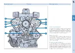
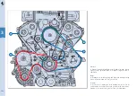
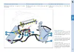
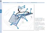
3.12
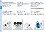
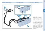
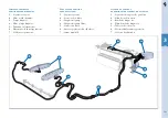
Raffreddamento
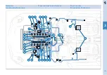
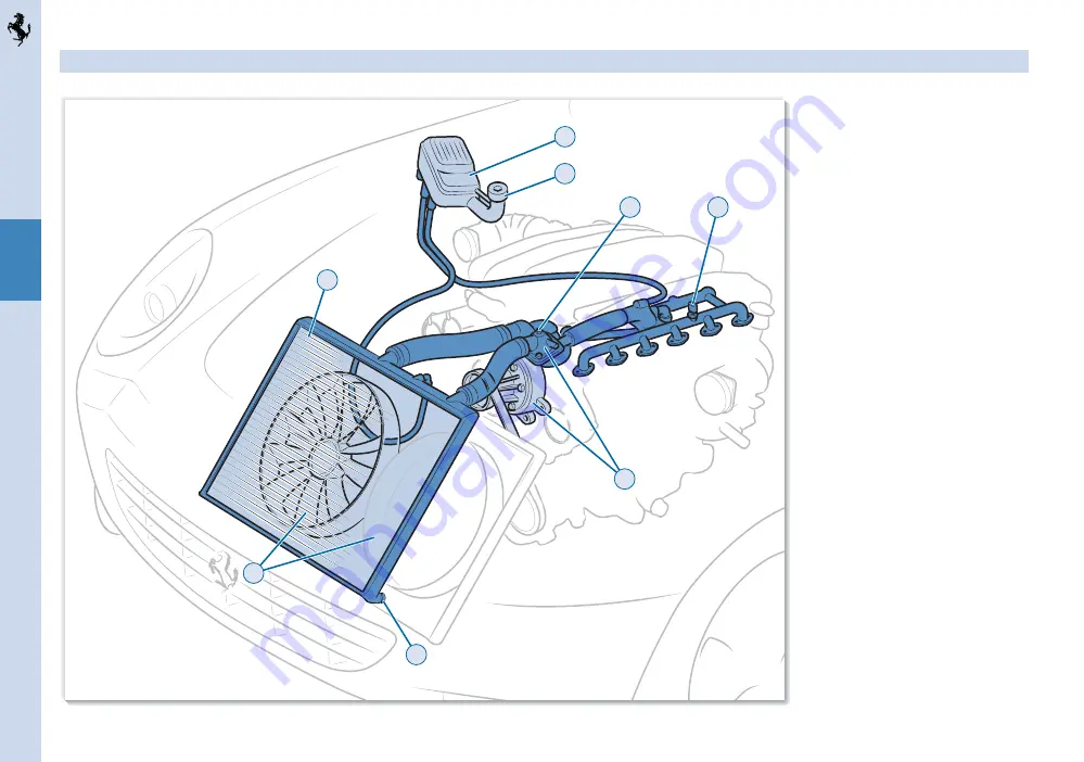
Schema impianto di raffreddamento
1
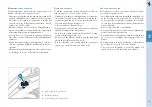
- Vite spurgo aria;
2
- Corpo pompa con termo-
stato;
3
- Radiatore acqua;
4
- Tappo di scarico;
5
- Elettroventilatori;
6
- Serbatoio espansione;
7
- Tappo di carico;
8
- Sensore NTC su colletto-
re uscita acqua dalla testa sinistra.
Cooling system
Refrigeración
Cooling system outline
1
- Air breathing screw;
2
- Pump body with ther-
mostat;
3
- Water radiator;
4
- Drainage cap;
5
- Electric fans;
6
- Expansion tank;
7
- Filler
cap;
8
- NTC sensor on left-hand head water
output manifold.
Esquema del sistema de refrigeración
1
- Tornillo de purgado de aire;
2
- Cuerpo de la
bomba con termostato;
3
- Radiador de agua;
4
- Tapón de drenaje;
5
- Electroventiladores;
6
- Depósito de expansión;
7
- Tapón de llenado;
8
- Sensor NTC en el colector de salida de agua
e la culata izquierda.
Summary of Contents for 612 scaglietti
Page 1: ......
Page 2: ...1 USO E MANUTENZIONE OWNER S MANUAL USO Y MANTENIMIENTO ...
Page 23: ...2 2 1 6 7 8 9 10 5 4 3 2 12 11 1 13 1 16 Targhette Data plates Etiquetas ...
Page 33: ...3 2 1 1 26 ...
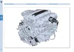
Page 161: ...160 3 3 2 Gruppo motore Engine assembly Grupo motor ...
Page 197: ...196 4 4 4 Cambio e differenziale Gearbox and differential Cambio y diferencial ...
Page 207: ...206 4 6 3 13 2 5 4 7 4 7 8 8 1 12 6 9 4 9 4 11 10 4 14 ...
Page 292: ......