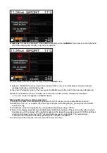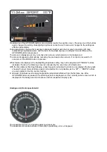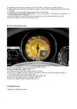
E5.04 Indications
on the TFT display
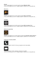
The driver is notified of a fault by the instrument panel via the following events:
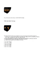
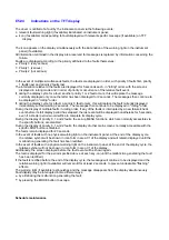
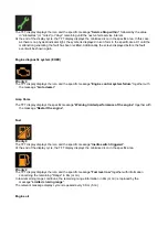
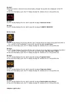
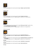
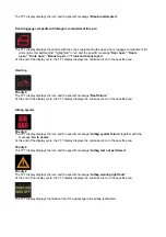
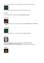
The icon appears on the display simultaneously with the illumination of the warning light on the instrument
panel (if available).
All information contained in the display area reserved for messages is replaced by information concerning the
failure.
Faults are displayed according to the priority attributed to the faults themselves:
In the event of multiple simultaneous faults, the faults are displayed in order, with priority 0 faults first, priority
1 faults next and priority 2 faults last.
The information relative to the faults are displayed for 5 seconds each, in "rolling" order. with the screens
displayed in rolling mode and in order of priority or occurrence of the relative fault event.
If, during the display cycle for a fault, another priority 1 or 2 fault occurs, this will replace the message
currently displayed only once the latter has been displayed for 2 seconds. The messages then continue to
be displayed in "rolling" order.
If, during the display cycle for a fault, a priority 0 fault occurs, this will replace the fault currently displayed
immediately, without waiting 2 seconds. The messages then continue to be displayed in "rolling" order.
During the display of multiple faults in rolling order, if any of the faults is interrupted by a new failure/check
event before its full display period has elapsed, the last event will be displayed nonetheless for 5 seconds,
even if a shorter period would suffice to complete its display cycle.
During the display of priority 0, 1 and 2 faults, the set-up MENU functions, which are normally accessible via
the specific buttons, are disabled.
During the display of priority 0, 1 and 2 faults, the display of other main screens normally accessible with the
specific DISP button is disabled.
The faults remain displayed for 20 seconds.
In the event of faults with no physical warning light on the instrument panel, at the end of the display cycle,
the relative symbol will be shown in icon form in area C1 of the display and will remain displayed until the
malfunction generating the fault has been rectified.
In the event of faults with a physical warning light on the instrument panel, at the end of the display cycle, the
relative symbol will not be shown in icon form in area C1 of the display.
Additionally, the screen displayed before the fault event will be shown again.
The fault is displayed for the period specified above at each key-on (until the malfunction generating the fault
has been rectified).
If the fault is rectified before the end of the display cycle, the message will continue to be displayed and the
relative warning light (if available) will remain lit for at least 2 seconds, to prevent undesirable "flashing"
effects.
The warning light (if available) extinguishes and the message disappears from the display simultaneously.
Fault display may be interrupted in two different ways:
relevant fault warning light (if available) illuminated on instrument panel;
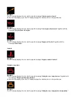
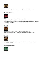
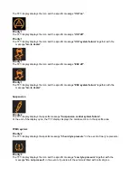
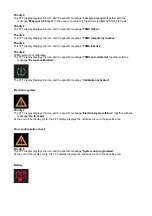
icon (if available) corresponding to fault displayed with relevant specific message (if available) on TFT
display.
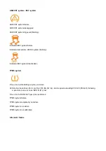
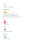
Priority 0 (very serious)
Priority 1 (serious)
Priority 2 (not serious)
by eliminating the malfunction generating the fault;
by pressing the MODE button to escape.
Schedule maintenance
Summary of Contents for California
Page 19: ...Z Tyre type and pressure label ...
Page 20: ...04 02 Assembly number Assembly number A Assembly number label ...
Page 21: ...04 03 Chassis number Chassis number B Punched chassis number ...
Page 22: ...04 04 Engine type and number Engine type and number C Punched engine type and number ...
Page 23: ...04 05 Chassis number Chassis number D Chassis number ...
Page 24: ...04 06 Gearbox type and number Gearbox type and number E Gearbox type and number plate ...
Page 25: ...04 07 Vehicle identification Vehicle identification K VIN label Vehicle Identification Number ...
Page 28: ...04 10 Fuel Fuel I Fuel label ...
Page 29: ...04 11 Paintwork Paintwork L Paintwork label ...
Page 30: ...04 12 Emissions control Emissions control M Emissions control data label ...
Page 31: ...04 13 Airbag Airbag N Do not install child seat on passenger seat label ...
Page 32: ...04 14 Airbag Airbag O Airbag maintenance label ...
Page 33: ...04 15 Airbag Airbag P Airbag warning label ...
Page 43: ...Fluids and lubricants table Model Fluids and lubricants table Download ...
Page 71: ...Screw the cap A back on tightly ...
Page 104: ...Connect the battery F2 01 ...
Page 118: ...Vehicle Setup Parameter Check Form Model Vehicle Setup Parameter Check Form Download ...
Page 520: ...A DCT gearbox clutch oil tank and clutch oil pump B Clutch oil pipes C Clutch oil radiator ...
Page 623: ...CCM Brake Disc Wear Form Model All Models CCM Brake Disc Wear Form Download ...
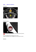
Page 1070: ...A Horn button B Engine start button C Manettino ...
Page 1102: ...Perform the respective cycle with the DEIS diagnostic tester ...
Page 1144: ...Connect the battery F2 01 ...
Page 1220: ...Precautions and guidelines for using the RHT retractable hard top ...
Page 1334: ...Undo the indicated fasteners Retrieve the indicated shims Release the clip 1 ...
Page 1335: ...Remove the indicated clip Undo the indicated screw Undo the screws indicated ...
Page 1452: ...Refit the rear wheelhouses E3 05 Connect the battery F2 01 ...
Page 1453: ...F2 07 Lights Diagnosing condensation in headlamps ...
Page 1561: ...Ss Sensor signal λ Lambda ratio excess g Rich mixture M Lean mixture ...
Page 1570: ...Refit the DCT gearbox C2 03 Connect the battery F2 01 ...
Page 1656: ...G Heater evaporator H Pollen filter I Air vents M Expansion valve ...
Page 1677: ...Refit the front wheelhouses E3 05 ...
Page 1686: ...Refit the caps 1 Refit the engine compartment cosmetic shields E3 13 ...

