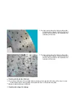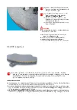
disc replacement is necessary.
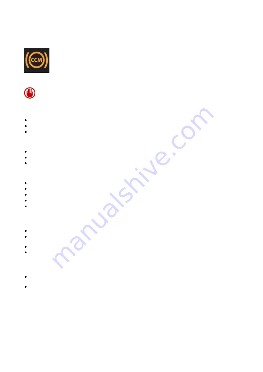
The user is warned of this condition by the appearance of the message:
“CCM brake discs worn”
on the
display, together with the specific amber symbol. At the end of the display cycle, or when the MODE
button is pressed (with
“Escape”
function), the symbol is reduced to icon form.
An RLI for “Number of brake disc replacements” is also generated, identifying the number of times that the
discs have been replaced.
Once the brake discs have been replaced, the wear index may be reset on the instrument panel.
To maintain a record of the latest brake wear index reset, three values are stored in the statistics memory for
the front and rear brakes, which are updated upon reset (with the possibility of storing the last seven
resets):
At each service, submit the following data (printing out the parameters from the instrument panel):
There are essentially
5
different scenarios possible:
The wear index indicated on the instrument panel may only be reset when the discs are replaced,
once the wear index exceeds 100%.
Number of brake disc changes counter: --------- (dimensionless number)
Kilometres at first disc brake change: --------- Km
Wear percentage at first disc brake change: --------- %
vehicle serial number;
vehicle mileage (“Odometer” parameter);
“
Disc Wear Index” value.
1 - Replacing all carbon discs due to vehicle usage;
2 - Replacing one carbon disc (or two discs on same axle) due to failure;
3 - Replacing a working instrument panel (dialogue with diagnostic instrument possible);
4 - Replacing of a malfunctioning instrument panel (dialogue with diagnostic instrument not possible);
5 - Replacing the carbon discs before reaching wear threshold (“Disc Wear Index” parameter < 100%).
1 - Replacing the carbon discs due to vehicle usage
In this situation, the amber warning signal on the TFT display is lit.
Use the diagnostic instrument to verify from the instrument panel that the disc wear index has exceeded
100%.
Replace the carbon discs.
Reset the carbon disc wear index on the instrument panel with the diagnostic instrument.
2 - Replacing one carbon disc (or two discs on same axle) due to failure
In this situation, only one disc (or two discs on the same axle) are replaced, without modifying the
parameters on the instrument panel.
In other terms, the “Disc Wear Index” parameter is left at the value for the discs not being replaced
(partially worn).
3 - Replacing a working instrument panel (dialogue with diagnostic instrument possible)
Summary of Contents for California
Page 19: ...Z Tyre type and pressure label ...
Page 20: ...04 02 Assembly number Assembly number A Assembly number label ...
Page 21: ...04 03 Chassis number Chassis number B Punched chassis number ...
Page 22: ...04 04 Engine type and number Engine type and number C Punched engine type and number ...
Page 23: ...04 05 Chassis number Chassis number D Chassis number ...
Page 24: ...04 06 Gearbox type and number Gearbox type and number E Gearbox type and number plate ...
Page 25: ...04 07 Vehicle identification Vehicle identification K VIN label Vehicle Identification Number ...
Page 28: ...04 10 Fuel Fuel I Fuel label ...
Page 29: ...04 11 Paintwork Paintwork L Paintwork label ...
Page 30: ...04 12 Emissions control Emissions control M Emissions control data label ...
Page 31: ...04 13 Airbag Airbag N Do not install child seat on passenger seat label ...
Page 32: ...04 14 Airbag Airbag O Airbag maintenance label ...
Page 33: ...04 15 Airbag Airbag P Airbag warning label ...
Page 43: ...Fluids and lubricants table Model Fluids and lubricants table Download ...
Page 71: ...Screw the cap A back on tightly ...
Page 104: ...Connect the battery F2 01 ...
Page 118: ...Vehicle Setup Parameter Check Form Model Vehicle Setup Parameter Check Form Download ...
Page 520: ...A DCT gearbox clutch oil tank and clutch oil pump B Clutch oil pipes C Clutch oil radiator ...
Page 623: ...CCM Brake Disc Wear Form Model All Models CCM Brake Disc Wear Form Download ...
Page 1070: ...A Horn button B Engine start button C Manettino ...
Page 1102: ...Perform the respective cycle with the DEIS diagnostic tester ...
Page 1144: ...Connect the battery F2 01 ...
Page 1220: ...Precautions and guidelines for using the RHT retractable hard top ...
Page 1334: ...Undo the indicated fasteners Retrieve the indicated shims Release the clip 1 ...
Page 1335: ...Remove the indicated clip Undo the indicated screw Undo the screws indicated ...
Page 1452: ...Refit the rear wheelhouses E3 05 Connect the battery F2 01 ...
Page 1453: ...F2 07 Lights Diagnosing condensation in headlamps ...
Page 1561: ...Ss Sensor signal λ Lambda ratio excess g Rich mixture M Lean mixture ...
Page 1570: ...Refit the DCT gearbox C2 03 Connect the battery F2 01 ...
Page 1656: ...G Heater evaporator H Pollen filter I Air vents M Expansion valve ...
Page 1677: ...Refit the front wheelhouses E3 05 ...
Page 1686: ...Refit the caps 1 Refit the engine compartment cosmetic shields E3 13 ...

