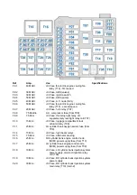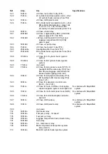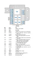
F-01
60 MAXI
+30 fuse for electric engine cooling fan
relay (T16) - first speed
F-02
30 MAXI
+30 fuse, ABS (valves)
F-03
30 MAXI
+30 fuse, ignition switch
F-04
50 MAXI
+30 fuse, ABS (pump)
F-05
40 MAXI
+30 fuse, A.C. node (NCL)
F-06
50 MAXI
+30 fuse for electric engine cooling fan
relay (T15) - second speed
F-07
20 MAXI
+30 fuse, horn relay (T07)
F-08 7.5
Middle A.C.
compressor fuse (from T08)
F-09
7.5 Mini
+30 fuse, third stop light relay, LH
supplementary rear light relay coil (T37)
F-10
15 Mini
+30 fuse, luggage compartment lock
actuator relay (T06)
F-11
25 Mini
LH cylinder bank oxygen sensor fuse (from
T09)
F-14
15 Mini
+30 fuse, high beam relays
F-15
7.5 Mini
+30 fuse, alternator sensing
F-16
25 Mini
RH cylinder bank engine control node
(NCM) power supply fuse (from T10)
F-17
25 Mini
LH cylinder bank engine control node
(NCM) power supply fuse (from T09)
F-18
10 Mini
+30 fuse, LH cylinder bank injection system
power supply, main LH injection relay
coil (T09)
F-19
10 Mini
+30 fuse, RH cylinder bank injection system
power supply
F-20
30 Mini
+30 fuse, RH cylinder bank injection system
main relay (T10) (main 2)
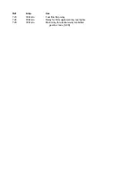
Ref
Amp.
Use
Specifications
Summary of Contents for California
Page 19: ...Z Tyre type and pressure label ...
Page 20: ...04 02 Assembly number Assembly number A Assembly number label ...
Page 21: ...04 03 Chassis number Chassis number B Punched chassis number ...
Page 22: ...04 04 Engine type and number Engine type and number C Punched engine type and number ...
Page 23: ...04 05 Chassis number Chassis number D Chassis number ...
Page 24: ...04 06 Gearbox type and number Gearbox type and number E Gearbox type and number plate ...
Page 25: ...04 07 Vehicle identification Vehicle identification K VIN label Vehicle Identification Number ...
Page 28: ...04 10 Fuel Fuel I Fuel label ...
Page 29: ...04 11 Paintwork Paintwork L Paintwork label ...
Page 30: ...04 12 Emissions control Emissions control M Emissions control data label ...
Page 31: ...04 13 Airbag Airbag N Do not install child seat on passenger seat label ...
Page 32: ...04 14 Airbag Airbag O Airbag maintenance label ...
Page 33: ...04 15 Airbag Airbag P Airbag warning label ...
Page 43: ...Fluids and lubricants table Model Fluids and lubricants table Download ...
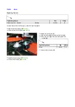
Page 71: ...Screw the cap A back on tightly ...
Page 104: ...Connect the battery F2 01 ...
Page 118: ...Vehicle Setup Parameter Check Form Model Vehicle Setup Parameter Check Form Download ...
Page 520: ...A DCT gearbox clutch oil tank and clutch oil pump B Clutch oil pipes C Clutch oil radiator ...
Page 623: ...CCM Brake Disc Wear Form Model All Models CCM Brake Disc Wear Form Download ...
Page 1070: ...A Horn button B Engine start button C Manettino ...
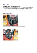
Page 1102: ...Perform the respective cycle with the DEIS diagnostic tester ...
Page 1144: ...Connect the battery F2 01 ...
Page 1220: ...Precautions and guidelines for using the RHT retractable hard top ...
Page 1334: ...Undo the indicated fasteners Retrieve the indicated shims Release the clip 1 ...
Page 1335: ...Remove the indicated clip Undo the indicated screw Undo the screws indicated ...
Page 1452: ...Refit the rear wheelhouses E3 05 Connect the battery F2 01 ...
Page 1453: ...F2 07 Lights Diagnosing condensation in headlamps ...
Page 1561: ...Ss Sensor signal λ Lambda ratio excess g Rich mixture M Lean mixture ...
Page 1570: ...Refit the DCT gearbox C2 03 Connect the battery F2 01 ...
Page 1656: ...G Heater evaporator H Pollen filter I Air vents M Expansion valve ...
Page 1677: ...Refit the front wheelhouses E3 05 ...
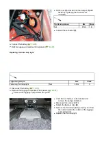
Page 1686: ...Refit the caps 1 Refit the engine compartment cosmetic shields E3 13 ...

