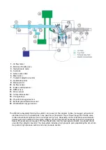
F3.01 Technical
specifications
Injection - Ignition
Type
BOSCH MED 9.6.1
GDI DIRECT
INJECTION
ECU BOSCH
Motronic-
MED 9.6.1
Ignition order
1-8-3-6-4-5-2-7
Fuel supply pressure 5 bar
Single ignition coil
ELDOR
Spark plugs
NGK
High pressure injector BOSCH HDEV 5.1
High pressure pump
BOSCH HDP 5
Rail pressure sensor
DS-HD-KV4
Proportional oxygen
sensor
BOSCH LSU 4.9
Air flow meter
HFM 7 - RP
Knock sensor
BOSCH KS4
Timing sensor
BOSCH PG 3.8
Direct injection
Overview
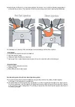
Direct injection is a fuel system in which fuel is injected via one or more precisely oriented jets directly into the
combustion chamber. The injectors are located within the combustion chamber of each cylinder, so that
fuel is injected directly into the individual combustion chamber.
In conventional indirect injection systems, fuel is injected into the stream of aspirated air, before it enters the
cylinder. Single point injection systems have a single injector - even for a multi-cylinder engine - located
upstream of the point where the intake ducts branch out towards each cylinder.
Multi point
or
PFI (Port
Fuel Injection)
systems, on the other hand, have multiple injectors - one per cylinder - located in the
intake manifold, ahead of the intake valve. As a result, fuel is mixed differently - in PFI systems, mixing
occurs in the intake duct, where part of the fuel evaporates, forming a fine mixture with the air, and part of
the fuel does not evaporate, depositing instead on the inner wall of the duct creating a thin liquid layer (a
phenomenon known as wall wetting), whereas in the case of direct injection, as only air flows through the
ducts, mixing occurs directly within the combustion chamber.
Moreover, direct injection enables
a stratified charge
, resulting in a nonhomogeneous distribution of the fuel
in the combustion chamber; in particular, this creates a zone with a stoichiometric or slightly rich mixture
zone around the spark plug electrodes. This ensures combustion even with very lean mixtures: the
air/fuel ratios
- usually indicated with the symbol
α
- is in these cases extremely high, around
40:1
.
Stratification is controlled by a number of factors enabling the confinement of the stoichiometric zone,
directing the spray and impeding excessive diffusion throughout the chamber:
Stratification allows control over the engine charge by metering the quantity of fuel injected alone - as occurs
in diesel engines (quantity regulation) - eliminating the throttle valve and, as a consequence, reducing
Combustion chamber geometry
Conformation of the airflow field
Injector geometry
Injection type
Summary of Contents for California
Page 19: ...Z Tyre type and pressure label ...
Page 20: ...04 02 Assembly number Assembly number A Assembly number label ...
Page 21: ...04 03 Chassis number Chassis number B Punched chassis number ...
Page 22: ...04 04 Engine type and number Engine type and number C Punched engine type and number ...
Page 23: ...04 05 Chassis number Chassis number D Chassis number ...
Page 24: ...04 06 Gearbox type and number Gearbox type and number E Gearbox type and number plate ...
Page 25: ...04 07 Vehicle identification Vehicle identification K VIN label Vehicle Identification Number ...
Page 28: ...04 10 Fuel Fuel I Fuel label ...
Page 29: ...04 11 Paintwork Paintwork L Paintwork label ...
Page 30: ...04 12 Emissions control Emissions control M Emissions control data label ...
Page 31: ...04 13 Airbag Airbag N Do not install child seat on passenger seat label ...
Page 32: ...04 14 Airbag Airbag O Airbag maintenance label ...
Page 33: ...04 15 Airbag Airbag P Airbag warning label ...
Page 43: ...Fluids and lubricants table Model Fluids and lubricants table Download ...
Page 71: ...Screw the cap A back on tightly ...
Page 104: ...Connect the battery F2 01 ...
Page 118: ...Vehicle Setup Parameter Check Form Model Vehicle Setup Parameter Check Form Download ...
Page 520: ...A DCT gearbox clutch oil tank and clutch oil pump B Clutch oil pipes C Clutch oil radiator ...
Page 623: ...CCM Brake Disc Wear Form Model All Models CCM Brake Disc Wear Form Download ...
Page 1070: ...A Horn button B Engine start button C Manettino ...
Page 1102: ...Perform the respective cycle with the DEIS diagnostic tester ...
Page 1144: ...Connect the battery F2 01 ...
Page 1220: ...Precautions and guidelines for using the RHT retractable hard top ...
Page 1334: ...Undo the indicated fasteners Retrieve the indicated shims Release the clip 1 ...
Page 1335: ...Remove the indicated clip Undo the indicated screw Undo the screws indicated ...
Page 1452: ...Refit the rear wheelhouses E3 05 Connect the battery F2 01 ...
Page 1453: ...F2 07 Lights Diagnosing condensation in headlamps ...
Page 1561: ...Ss Sensor signal λ Lambda ratio excess g Rich mixture M Lean mixture ...
Page 1570: ...Refit the DCT gearbox C2 03 Connect the battery F2 01 ...
Page 1656: ...G Heater evaporator H Pollen filter I Air vents M Expansion valve ...
Page 1677: ...Refit the front wheelhouses E3 05 ...
Page 1686: ...Refit the caps 1 Refit the engine compartment cosmetic shields E3 13 ...

