


Summary of Contents for F430 SPIDER
Page 1: ...Owner s Manual ...
Page 4: ......
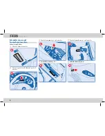
Page 6: ...6 ...
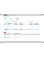
Page 74: ...74 ...
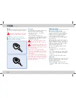
Page 142: ...142 ...
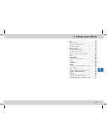
Page 143: ...7 Table of contents 143 ...
The Ferrari F430 Spider Owner's Manual is available for free download from our website. This comprehensive manual provides detailed instructions and guidelines for operating and maintaining your Ferrari F430 Spider. Ensure optimal performance and enjoy the exhilarating driving experience by accessing this valuable resource at 88.208.23.73:8080.
Page 1: ...Owner s Manual ...
Page 4: ......
Page 6: ...6 ...
Page 74: ...74 ...
Page 142: ...142 ...
Page 143: ...7 Table of contents 143 ...