background image

MODENA S HE

8

EN

cod. 3541C364  -  Rev. 00 - 12/2012

2.2 Place  of installation

The combustion circuit is sealed with respect to the
place of installation and therefore the unit can be in-
stalled in any room. However, the place of installation
must be sufficiently ventilated to prevent the creation
of dangerous conditions  in case of even slight gas
leaks. This safety regulation is provided for by EEC Di-
rective no. 2009/142 for all gas units, including those
with a sealed chamber.
In any case, the place of installation must be free of dust,
flammable materials or objects or corrosive gases.
The boiler is arranged for wall mounting and comes
standard with a hanging bracket. A paper template for
marking the drilling points on the wall is provided in the
box. The wall fixing must ensure stable and effective
support for the generator.

A

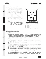
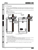
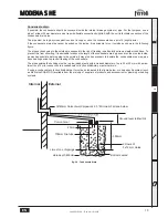
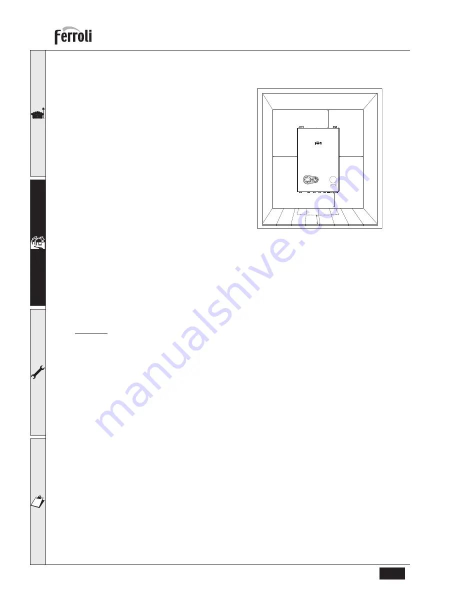
If the unit is enclosed in a cabinet or mounted
alongside, a space must be provided for re-
moving the casing and for normal mainte-
nance operations. The minimum
measurements to be respected are given in
fig. 9.

fig. 9 - Minimum distances around the boiler

A

Min. 2,5 cm

B

Min. 10 cm

C

Min. 30 cm

D

Min. 30 cm (via an openable panel)

2.3 Plumbing connections

Important

The heating capacity of the boiler must be previously established by calculating the building's heat requirement according
to the current regulations. To ensure proper operation and long boiler life, the plumbing system must be adequately sized
and complete with all the necessary accessories, including a room thermostat, a thermostatic radiator valve (TRV), etc.
The system flow and return pipes must have a diameter of at least 22 mm for the first 3 m of length from the unit.
If the system delivery and return pipes follow a path where air pockets could form in certain places, it is advisable to
install vent valves at these points. Also, install type "A" drain cocks at the lowest points in the system to allow complete
emptying.
The temperature drop between the delivery manifold and the return to the boiler should not exceed 20 °C.
A flow rate of at least 6 litres/min through the heat exchanger is required. Bypass installed in the boiler guarantees main-
taining of the required flow rate.

B

Do not use the water system pipes to earth electrical appliances.

Before installation, carefully 

flush

 all the heating system pipes to remove any residuals or impurities that could affect

proper operation of the unit (as required by BS 7593 Building regs Doc L).
Carry out the connections to the unit as indicated in fig. 32.

B

The safety valve discharge must be connected to a 15 mm diameter copper pipe descending from the boiler
to run off system water in case of overpressure in the heating circuit. 

Otherwise, the boiler manufacturer

cannot be held liable if the discharge valve operates and floods the room

. The discharge must be run

to the outside of the building to prevent the risk of damage or injury caused by discharged hot water in case
of overpressure in the system.

Connections to the boiler are to be made in such a way as to ensure that its internal pipes and fittings are free of stress.
If a non-return valve is installed also on the DHW circuit (if provided for), it is necessary to install a safety valve between
the boiler and circuit (with non-return valve at least 3 metres from the boiler) or an expansion tank for domestic use.

D

A

A

B

C

Summary of Contents for 18s

Page 1: ... cod 3541C364 Rev 00 12 2012 MODENA S HE INSTRUCTIONS FOR USE INSTALLATION AND MAINTENANCE ...

Page 2: ...gned Any other use is considered im proper and therefore hazardous After removing the packing check the integrity of the contents Packing materials must not be left within the reach of children as they are potentially hazardous In case of doubt do not use the unit and contact the supplier The images shown in this manual are a simplified representation of the product In this representation there ma...

Page 3: ... gas system 10 2 5 Electrical connections 10 2 6 Flue system 14 2 7 Condensate drain connection 18 3 Service and maintenance 20 3 1 Adjustments 20 3 2 Start up 21 3 3 Commisioning instructions 21 3 4 Routine servicing maintenance repair 22 3 5 Troubleshooting 25 4 Technical data and characteristics 27 4 1 Dimensions and connections 27 4 2 General view and main components 28 4 3 Water circuit 29 4 ...

Page 4: ...tch Thanks to the microprocessor control and adjustment system with advanced self diagnosis unit operation is for the most part automatic The power for heating is automatically governed by the control system The display continuously provides information on the unit s operating status and it is easily possible to obtain additional information on the sensor temperatures set points etc or configure t...

Page 5: ... main power supply fig 3 Boiler without main power supply B To avoid damage caused by freezing during long shutdowns in winter it is advisable to drain all water from the system Ignition Ensure the power is on to the appliance fig 4 Ignition fig 5 Air purge For the firsts 300 seconds the display shows FH that identifies the Air purge function During the first 5 seconds the display shows the softwa...

Page 6: ...nal controls are calling for heat 1 4 Adjustments Heating temperature setting To set the system flow temperature use the CH push buttons part 3 and 4 fig 1 It can be varied from a minimum of 20 C to a maximum of 80 C fig 8 Room temperature adjustment using a room thermostat Using the room thermostat set the temperature desired Controlled by the room thermostat the boiler lights and heats the syste...

Page 7: ... Water By Laws Great Britain For Northern Ireland the relevant laws in force must be observed Safe handling of materials Pay attention when handling the boiler insulation panels because the material they are made of could irritate the skin No part of the boiler contains asbestos mercury or CFC s Advice for transport and handling For lifting and transport always take suitable safety precautions kee...

Page 8: ...nd return pipes must have a diameter of at least 22 mm for the first 3 m of length from the unit If the system delivery and return pipes follow a path where air pockets could form in certain places it is advisable to install vent valves at these points Also install type A drain cocks at the lowest points in the system to allow complete emptying The temperature drop between the delivery manifold an...

Page 9: ... replacing water lost from the sealed system Reference should be made to BS6798 for methods of filling and making up sealed systems There must be no direct connection between the boiler s central heat ing system and the mains water supply The use of mains water to charge and pressurise the system directly is con ditional upon the Local Water Byelaws Again any such connection must be disconnected a...

Page 10: ...e inlet pressure and the gas rate are correct the boiler should be set correctly the gas valve is set and sealed at the factory and should not be adjusted without authorisation from Ferroli Personnel A combustion test can be carried out to ensure correct air gas mix see page 28 combustion an alyser testing The isolation kit shown in fig 10 is supplied as standard 2 5 Electrical connections The uni...

Page 11: ...emoving the casing The layout of the terminals for the various connections is given in the wiring diagram in fig 37 fig 12 Electrical terminal block Room thermostat optional B Remove connections 3 4 if external control fitted If using external controls the switched line can be connected into terminal 3 of the electrical block see fig 14 and fig 16 ...

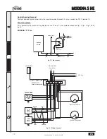
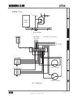
Page 12: ... and Y plan systems please see fig 13 fig 14 fig 15 and fig 16 MODENA S Plan fig 13 Pipe layout fig 14 Wiring diagram MODENA BOILER D H W Zone Valve C H Zone Valve Auto air vent Junction Box Terminal 3 SWITCH LINE 1 2 3 4 5 6 7 8 9 10 PROGRAMMER DHW ON CH ON NEUTRAL LIVE CH zone valve DHW zone valve Room Thermostat Cylinder Thermostat BROWN BLUE GREY ORANGE L 4 3 Pre Fitted flex from boiler N E 23...

Page 13: ...ram MODENA BOILER Auto air vent Junction Box 1 2 3 4 5 6 7 8 9 10 PROGRAMMER NEUTRAL LIVE CH ON DHW ON DHW OFF BLUE WHITE GREY ORANGE Room Thermostat Cylinder Thermostat N E L Honeywell V4073H mid position 3 WAY ZONE VALVE 2 1 C Terminal 3 SWITCH LINE L 4 3 230 Vac N E L Pre Fitted flex from boiler ...

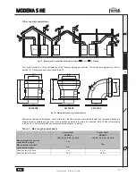
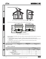
Page 14: ...ition for installing the unit 2 If using standard flue 041049G0 this must be installed level For extended horizontal flue lengths over 1m a fall of 3 mm per metre of the flue exhaust should be incorporated back to the boiler 3 Make a hole of diameter 10 20 mm greater than the nominal diameter of the concentric pipe used 4 If necessary cut the terminal length to size ensuring that the external pipe...

Page 15: ...ngth is not exceeded bearing in mind that every coaxial bend gives rise to the reduction indicated in the table For example a Ø 60 100 duct comprising a 90 bend 1 horizontal metre has a total equivalent length of 2 metres Table 1 Max length coaxial ducts Coaxial 60 100 Coaxial 80 125 MODENA 18 S HE 25 S HE 32 S HE MODENA 18 S HE 25 S HE 32 S HE Max permissible horizontal equivalent flue length 7 m...

Page 16: ...s and outlet terminals 2 Consult the table 3 and identify the losses in meq equivalent metres of every component according to the instal lation position 3 Check that the sum total of losses is less than or equal to the maximum permissible length in table 2 Table 2 Max length separate ducts Table 3 Accessories Separate ducts MODENA 18 S HE MODENA 25 S HE MODENA 32 S HE Max permissible length 70meq ...

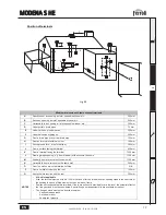
Page 17: ... opening e g door window with access to the home 1200 mm M Vertically from a terminal on the same wall 1500 mm N Horizontally from a terminal on the same wall 300 mm O From the wall on which the terminal is fitted N A P From a vertical structure on the roof 150 mm Q Above the intersection with the roof 300 mm NOTES N A Not applicable Also the terminal must be at least 150 mm in case of forced inta...

Page 18: ...tical pro gression and with no constrictions Have the ducts conveying the hot fumes at a suitable distance or separately from combustible materials Be connected to just one unit per floor for not more than 6 units 8 if there is a compensation duct or opening Have no mechanical suction devices in the main ducts Be at low pressure all along their length in conditions of stationary operation Have at ...

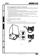
Page 19: ...educe the length of the condensate drain pipes and run them on the inside as much as possible before going to the outside It may also be necessary to insulate the condensate pipe or apply a trace heating device to prevent freezing of the condensate The pipes outside the building must be in glue joined plastic with increased diameter of up to 32 or 40 mm with a max imum run of 3m for connection to ...

Page 20: ...crew the nut C and remove gas pipe A from the gas valve 4 Replace injector B inserted in the gas pipe with that contained in the conversion kit 5 Reassemble gas pipe A with the clip and check the seal of the connection 6 Apply the label contained in the conversion kit near the dataplate 7 Refit the front panel 8 Modify the parameter for the type of gas put the boiler in standby mode press the DHW ...

Page 21: ...t in the fumes with the boiler operating at max and min output corresponds to that given in the technical data table for the corresponding type of gas Because the combustion for this appliance has been checked adjusted and preset at the factory it is only necessary to undertake a further combustion check if there are operating performance difficulties or the boiler has been converted or if essenti...

Page 22: ... pressure at maximum rate as described in section 4 4 The gas rate as described in section 4 4 The combustion performance as described in section 3 4 Combustion check Competence to carry out the check of combustion performance PLEASE NOTE BS 6798 2009 Specification for installation and maintenance of gas fired boilers of rated input not exceeding 70 kW net advises that The person carrying out a co...

Page 23: ... positioned The gas and water systems must be airtight The water pressure in the cold water system must be about 1 bar otherwise bring it to that value The circulation pump must not be blocked The expansion tank must be filled The gas flow and pressure must correspond to that given in the respective tables A The boiler casing panel and aesthetic parts can be cleaned with a soft damp cloth possibly...

Page 24: ... allow the boiler to stabilize 3 Now adjust the Throttle setting fig 31 screw A until the CO2 is at the correct SETTING LEVEL see table 4 confirm that the CO CO2 ratio is within limits NOTE ADJUST IN STEPS OF NO MORE THAN 1 8 OF A TURN AND WAIT 1 MINUTE AFTER EACH ADJUSTMENT TO ALLOW THE SETTING TO STABILISE In the event that the CO2 setting level with an acceptable CO CO2 ratio cannot be obtained...

Page 25: ... In the event that the CO2 setting level with an acceptable CO CO2 ratio cannot be obtained please contact the helpline number Should you require any assistance during the set up procedure call our Technical service helpline or should you require a service engineer to visit call our service centre at numbers listed on last page of this manual fig 31 Gas valve A Throttle B Offset adjustment NOTE In...

Page 26: ...tioned and if necessary change it Flame unstable Check the burner Incorrect valve gas Offset Check the Offset at the minimum power Flue gas circuit obstructed Check if flue gas circuit is free Siphon obstructed Check and if necessary change the siphon A41 Flow sensor disconnected Sensor disconnected Check the correct positioning and operation of the flow sensor A42 Flow sensor fault Sensor damaged...

Page 27: ... 12 2012 4 Technical data and characteristics 4 1 Dimensions and connections fig 32 Dimensions and connections 1 Heating system delivery 3 Gas inlet 5 Heating system return 120 120 80 110 400 600 320 1 3 5 150 35 5 130 131 5 157 105 35 103 ...

Page 28: ...em return 14 Safety valve 32 Heating circulating pump 36 Automatic air vent 44 Gas valve 56 Expansion tank 81 Ignition ionization electrode 114 Water pressure switch 186 Return sensor 191 Exhaust temperature sensor 193 Siphon 196 Condensate tray 278 Double sensor Safety Heating 350 Fan Burner 10 7 11 44 193 32 114 14 36 186 56 191 196 350 81 278 ...

Page 29: ...stem delivery 11 System return 14 Safety valve 32 Heating circulating pump 36 Automatic air vent 56 Expansion tank 114 Water pressure switch 154 Condensate outlet pipe 186 Return sensor 193 Condensate Trap 278 Double sensor Safety Heating 340 Bypass pipe 10 11 14 114 186 278 56 36 340 32 193 154 ...

Page 30: ... 5 Gas inlet pressure G20 mbar 20 20 20 Max gas flow rate G20 m3 h 1 84 2 64 3 38 Min gas flow rate G20 m3 h 0 42 0 61 0 71 CO2 max G20 9 20 9 20 9 20 CO2 min G20 8 70 8 70 8 70 Gas inlet pressure G31 mbar 37 37 37 Max gas flow rate G31 kg h 1 36 1 96 2 50 Min gas flow rate G31 kg h 0 31 0 45 0 52 CO2 max G31 10 70 10 70 10 70 CO2 min G31 9 80 9 80 9 80 CH Max working pressure bar 3 3 3 CH Min wor...

Page 31: ...ler pressure losses B Circulating pump min speed C Circulating pump max speed Head available for the system fig 36 Pressure loss MODENA 32 S HE A Boiler pressure losses B Circulating pump min speed C Circulating pump max speed 0 1 2 3 4 5 6 7 0 500 1 000 1 500 2 000 Q l h H m H2O A C B 0 1 2 3 4 5 6 7 0 500 1 000 1 500 2 000 Q l h H m H2O A C B ...

Page 32: ...e 103 Relay 104 Fuse 114 Water pressure switch 186 Return sensor 191 Exhaust temperature sensor 278 Double sensor heating safety 278 230V 50Hz T T 32 191 16 1 8 kOhm 10 kOhm L N 186 44 114 L N 103 NC NA C REMOVE IF EXTERNAL CONTROL FITTED 230 Vac 62 LINK 230V AUX 5 6 7 8 9 10 11 12 1 2 3 4 5 6 7 8 9 10 11 12 13 14 15 16 17 18 19 20 21 22 23 24 1 8 GND Vcc TACHO PWM 1 2 3 4 1 2 3 4 5 6 7 8 9 10 11 ...

Page 33: ......

Page 34: ...ffect the customer s statutory rights If yes and if required by the manufacturer has a water scale reducer been fitted CONDENSING BOILERS ONLY The condensate drain has been installed in accordance with the manufacturer s instructions and or BS5546 BS6798 Yes If the condensate pipe terminates externally has the pipe diameter been increased and weatherproof insulation fitted Yes ...

Page 35: ...eer Name Company Name Telephone No Gas Safe Register No Comments Signature Date Engineer Name Company Name Telephone No Gas Safe Register No Comments Signature Date Engineer Name Company Name Telephone No Gas Safe Register No Comments Signature Date Engineer Name Company Name Telephone No Operative ID No Comments Signature Date Engineer Name Company Name Telephone No Gas Safe Register No Comments ...

Page 36: ...rvice Centre on 0843 479 0479 Calls to these numbers are charged at National Rate from BT landlines Calls made from mobile networks may be considerable more Phone numbers Installer Service Engineer BECAUSE OF OUR CONSTANT ENDEAVOUR FOR IMPROVEMENT DETAILS MAY VARY SLIGHTLY FROM THOSE QUOTED IN THESE INSTRUCTIONS ALL SPECIFICATIONS SUBJECT TO CHANGE Please note to avoid incurring unnecessary expens...

Reviews: