7
EN
BLUEHELIX 25K 50
Condensate drain
The condensate should be run inside as far as is practicably possible. For that purpose, use a pipe of at
least 22 mm diameter and a trap with flexible connection supplied with the unit to facilitate connection of
the condensate drain pipe.
The pipe must be in solvent weld plastic and not in copper, since the condensate has a pH of 4 (slightly
acid).
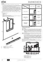
If the condensate drain pipe cannot be ended on the inside, it is advisable to run it outside as shown in
the following figure.
The pipe sections going to the outside are exposed to the risk of freezing in particularly extreme weather
conditions. To prevent this from occurring, it is advisable to reduce the length of the condensate drain
pipes and run them on the inside, as much as possible, before going to the outside. It may also be nec-
essary to insulate the condensate pipe or apply a trace heating device to prevent freezing of the con-
densate.
The pipes outside the building must be in solvent weld plastic with increased diameter of up to 32 or 40
mm with a maximum run of 3m for connection to a condensate collection soakaway or external drain.
If using a condensate collection soakaway, it must be as indicated in the figure below, or use a specific
system (such as Mc Alpine SOAK1GR) available from the majority of plumbing and heathing suppliers.
fig. 22 - Condensate drain
4. SERVICE AND MAINTENANCE
4.1 Adjustments
Gas conversion
The unit can operate on Natural Gas or LPG and is factory-set for use with one of these two gases, as
clearly shown on the packing and on the data plate. Whenever a different gas to that for which the unit
is arranged has to be used, a conversion kit will be required, proceeding as follows:
1.
Remove the front panel (
see
*** 'Opening the front panel' on page 8 ***).
2.
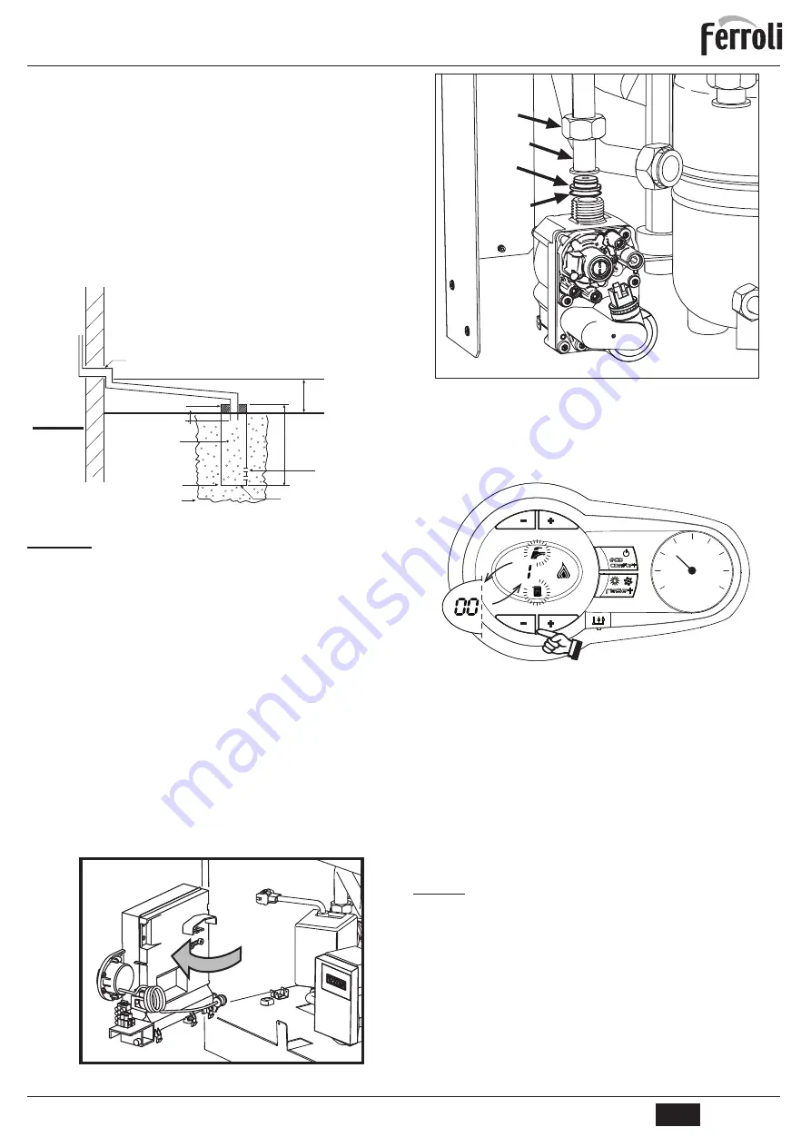
Undo the screw and rotate the control panel (see fig. 23).
3.
Unscrew ring
C
and remove gas pipe
A
from the gas valve (see fig. 24).
4.
Replace nozzle
B
inserted in the gas pipe with that contained in the conversion kit, interposing seal
D
(see fig. 24).
5.
Refit gas pipe
A
and check the tightness of the connection.
6.
Apply the label, contained in the conversion kit, near the data plate.
7.
Refit the front panel.
8.
Modify the parameter for the type of gas
:
SXWWKHERLOHULQVWDQGE\PRGH
SUHVVWKH'+:EXWWRQVGHWDLOVDQG
fig. 1 for 10 seconds: the display shows “
b01
“ flash-
ing.
SUHVVWKH'+:EXWWRQVGHWDLOVRU
fig. 1 to set parameter
00
(for operation with natural
gas) or
01
(for operation with LPG).
SUHVVWKH
h
button (detail 4 - fig. 1) until
“b06”
flashes on the display.
SUHVVWKH
DHW
buttons (details 1 or 2 - fig. 1) to set parameter
55
(for operation with natural
gas) or
70
(for operation with LPG).
SUHVVWKH'+:EXWWRQVGHWDLOVDQG
fig. 1 for 10 seconds.
WKHERLOHUZLOOUHWXUQWRVWDQGE\PRGH
9.
Using a combustion analyser connected to the boiler fume outlet, check that the CO
2
content in the
fumes, with the boiler operating at max. and min. output, matches that given in the technical data
table for the corresponding type of gas.
fig. 23
fig. 24
TEST mode activation
Press the heating buttons (details 3 and 4 - fig. 1) together for 5 seconds to activate the
TEST
mode. The boiler lights at the maximum heating power set as described in the fol-
lowing section.
7KHKHDWLQJDQG'+:V\PEROVILJ IODVKRQWKHGLVSOD\WKHKHDWLQJSRZHUZLOODS
pear alongside.
fig. 25 - TEST mode (heating power = 100%)
Press the heating buttons (details 3 and 4 - fig. 1) to increase or decrease the power
(Min.=0%, Max.=100%).
%\SUHVVLQJWKH'+:
“-”
button (detail 1 - fig. 1), boiler output is immediately adjusted
WRPLQ%\SUHVVLQJWKH'+:
“+”
button (detail 2 - fig. 1), boiler output is immedi-
ately adjusted to max. (100%).
,IWKH7(67PRGHLVDFWLYDWHGDQGHQRXJKKRWZDWHULVGUDZQWRDFWLYDWHWKH'+:PRGH
WKHERLOHUUHPDLQVLQ7(67PRGHEXWWKHZD\YDOYHJRHVWR'+:
To deactivate the TEST mode, press the heating buttons (details 3 and 4 - fig. 1) together
for 5 seconds.
The TEST mode is automatically deactivated in any case after 15 minutes or on stopping
RIKRWZDWHUGUDZLQJLIHQRXJKKRWZDWHUKDVEHHQGUDZQWRDFWLYDWHWKH'+:PRGH
Heating power adjustment
To adjust the heating power, switch the boiler to TEST mode (see sec. 4.1). Press the
heating buttons fig. 1 (details 3 and 4 - ) to increase or decrease the power (min. = 00 -
max. = 100). Press the RESET button within 5 seconds and the max. power will remain
that just set. Exit TEST mode (see sec. 4.1).
4.2 Startup
Before lighting the boiler
&KHFNWKHVHDORIWKHJDVV\VWHP
&KHFNFRUUHFWSUHILOOLQJRIWKHH[SDQVLRQWDQN
)LOOWKHZDWHUV\VWHPDQGPDNHVXUHDOODLUFRQWDLQHGLQWKHERLOHUDQGWKHV\VWHP
has been vented.
0DNHVXUHWKHUHDUHQRZDWHUOHDNVLQWKHV\VWHP'+:FLUFXLWVFRQQHFWLRQVRUERLO
er.
&KHFNFRUUHFWFRQQHFWLRQRIWKHHOHFWULFDOV\VWHPDQGHIILFLHQF\RIWKHHDUWKLQJV\V
tem.
0DNHVXUHWKHJDVSUHVVXUHIRUKHDWLQJLVWKDWUHTXLUHG
0DNHVXUHWKHUHDUHQRIODPPDEOHOLTXLGVRUPDWHULDOVLQWKHLPPHGLDWHYLFLQLW\RI
the boiler
External
32/40mm Solvent weld pipework 2.5° Minimum fall. See below
Cement seal
100mm Dia tube
Bottom sealed
Lime stone chippings
Ground level (either/Or)
Hole depth 400mm
25mm
2 Rows of
3x12 mm Holes
Internal
-300mm
2.5° Minimum fall
A
C
B
D
0
1
4
2
3
cod. 3541F704 - Rev. 00 - 12/2018


