BLUEHELIX TECH RRT 28 C
191
EN
cod. 3541N260 - Rev. 01 - 10/2017
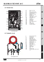
4.2 General view
4.3 Hydraulic circuit
fig. 54- General view
14
Pressure relief valve
16
Fan
32
Heating circulating pump
34
Heating temperature sensor
36
Automatic air vent
42
DHW temperature probe
44
Gas valve
56
Expansion tank
81
Ionization/ignition electrode
95
Diverter valve
114
Water pressure switch
136
Flow meter
137
Pressure probe
145
Water gauge
186
Return sensor
191
Fume temperature sensor
193
Trap
194
DHW exchanger
196
Condensate tray
350
Fan/Burner assembly
fig. 55- Hydraulic circuit
8
Domestic hot water outlet
9
Cold water inlet
10
System delivery
11
System return
14
Pressure relief valve
32
Heating circulating pump
34
Heating temperature sensor
36
Automatic air vent
42
DHW temperature probe
56
Expansion tank
74
System filling valve
95
Diverter valve
114
Water pressure switch
136
Flowmeter
137
Pressure probe
186
Return sensor
193
Trap
194
DHW exchanger
241
Automatic bypass (inside the pump
unit)
196
350
34
16
194
42
114
14
136
137
32
145
36
193
95
186
81
56
191
44
10
8
9
11
14
137
42
186
34
56
36
193
32
136
74
194
95
241
114


