29
Ferroli F 24 B
Cleaning the boiler and burner
The body and burner must not be cleaned with chemical products or wire brushes. Special care must
be taken over all the sealing systems pertaining to the sealed chamber (gaskets, cable clamps, etc.). In
addition, it is necessary to pay attention after performing all these operations to check and carry out all
the phases of ignition and thermostat operation, the gas valve and circulation pump.
After these checks, make sure there are no gas leaks.
Combustion analyser testing
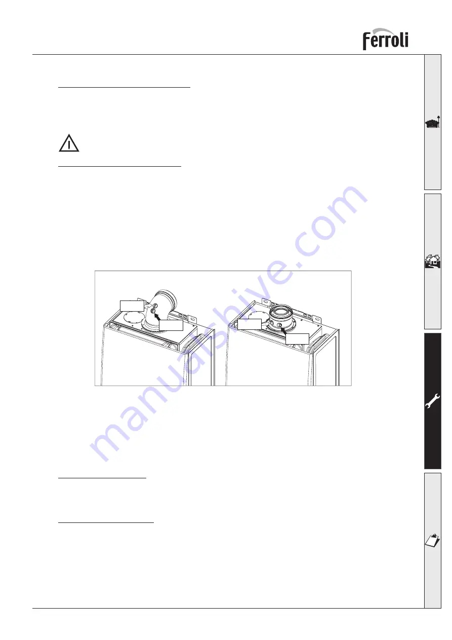
It is possible to analyse the combustion through the air and flue sampling points shown in fig. 17.
To make the measurement, it is necessary to:
1)
Open the flue sampling point
2)
Insert the probe;
3)
Turn on the hot water tap;
4)
Turn the domestic hot water stat to maximum;
5)
Allow the boiler to reach thermal equilibrium (10 - 15 min.);
6)
Wait 10 minutes for the boiler to stabilize
7)
Take the measurement.
fig. 17
3.4 Troubleshooting
Before beginning any fault finding ensure that gas, water and electricity are available.
WARNING
: DO NOT link any terminals on block X10 or X11 as this will damage the PCB beyond
repair.
Operating Sequence
With the power established the boiler is in its stand-by mode i. e. power on but no demand. The ope-
rational sequence for C.H. and D.H.W. are as follows:
Central Heating Mode
External Call for Heat:
The temperature regulator, built in or remote clock and room thermostat, if
fitted, must all call for heat. This will cause the pump to run.
Internal Call for Heat:
Low water pressure switch is calling for heat. If both external and internal calls
for heat are present the MF03 PCB will energise.
In demand the fan will go to high speed causing the air pressure switch to operate. If the overheat
(100°C) stat and the flue gas safety thermostat (100°) are closed circuit the ignition will operate and the
gas valve will be energised.
Flue
Flue
Air
Air


