DOMINA N 80 DGT
16
Fig. 17c
Fig. 17d
Fig. 17e
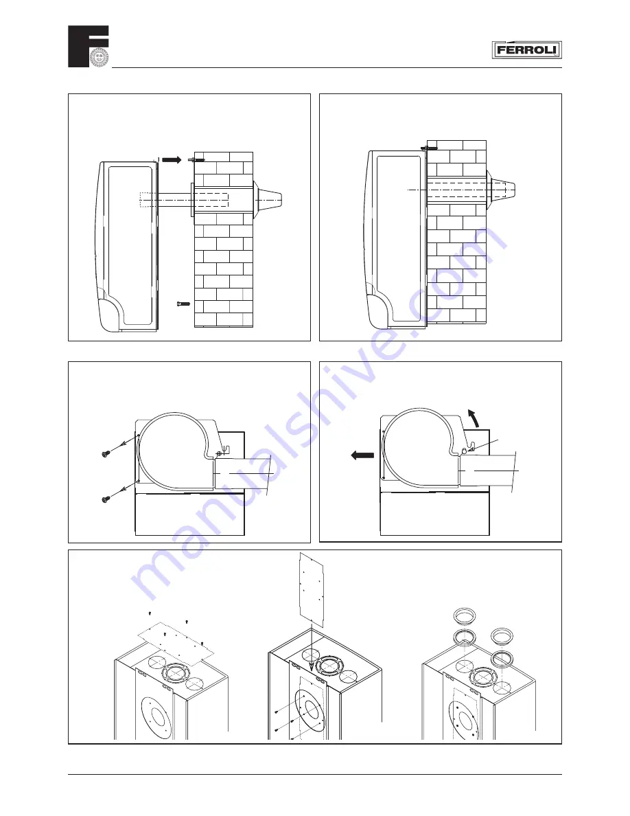
Remove fan by pulling off electrical connections. Pull
off air pressure switch tubes from the air pressure
switch remove 2 screws b. Rotate the fan upward to
disengage it from the securing pin a.
Fig. 17a
Fig. 17b
3.05 Domina top outlet fl ue conversion
Remove the securing screw that locates the fan
nozzle extension to the fan and remove the nozzle
extension and jointing mastic (this is not required
for top outlet fl ueing).
Fig. 16h
Fig. 16i
8.
Install the inner metal fl ue into the outlet, up to
the wallplate fl ange mark.
9.
Lift boiler with fl ue in place, engage inner and
outer fl ue, slide into position
9.
Make sure the inner fl ue is fully engaged in
the fl ue terminal, secure boiler with two nuts
and washers, sevure bottom of boiler using two
screws and washers.
b
b
1
2
a
Take off the four screws which fi x the top sealed
chamber cover, remove the cover and gasket. Rotate
the cover and gasket through 90° and fi t it to the
rear of the boiler to cover the original fl ue outlet.
Secure them both in place with the four screws
removed previously.
Summary of Contents for DOMINA N 80 DGT
Page 12: ...DOMINA N 80 DGT 12 3 01 Boiler Mounting Plate 149 178 131 Fig 13 ...
Page 46: ......
Page 47: ......


