DOMINA N 80 DGT
40
Key
16
Fan
32
Ce
n
tr
a
l he
ati
n
g
pump
3
4
Ce
n
tr
al
he
ati
n
g
fl
ow
temper
atur
e
s
e
n
so
r
4
2
D
o
me
sti
c
h
o
t
w
ater
fl
ow
temper
a
tur
e
se
n
so
r
4
3
A
ir
pr
e
ss
ur
e
sw
it
ch
44
G
a
s
va
lv
e
4
9
S
a
fet
y
therm
os
ta
t
50
Ce
n
tr
al
he
ati
n
g
limit
therm
os
ta
t
F
ig
.
44
Key
BR
B
row
n
B
LUE
B
lue
B
L
B
la
ck
W
W
hite
O
O
ran
ge
G
G
re
e
n
R
R
e
d
V
V
io
let
Y
Yell
ow
IMPOR
TANT
USE A ROOM THERMOST
A
T
(24 V)
WITHOUT VOL
TAGE TO THE CONT
ACTS.
CONNECTING 230 V TO THE ROOM
THERMOST
A
T
TERMINALS WILL
IRREP
ARABL
Y DAMAGE THE
ELECTRONIC BOARD.
6
2
T
ime
c
lo
ck
(
o
pti
o
n
)
7
2
R
oo
m
therm
os
ta
t
8
1
Ig
n
iti
o
n
ele
ctr
o
d
e
8
2
S
e
n
so
r
ele
ctr
o
d
e
11
4
L
ow
w
a
ter
pr
e
ss
ur
e
sw
it
ch
1
3
6
F
low
meter
1
3
8
O
ut
si
d
e
temper
a
tur
e
s
e
n
so
r
1
3
9
R
oo
m
u
n
it
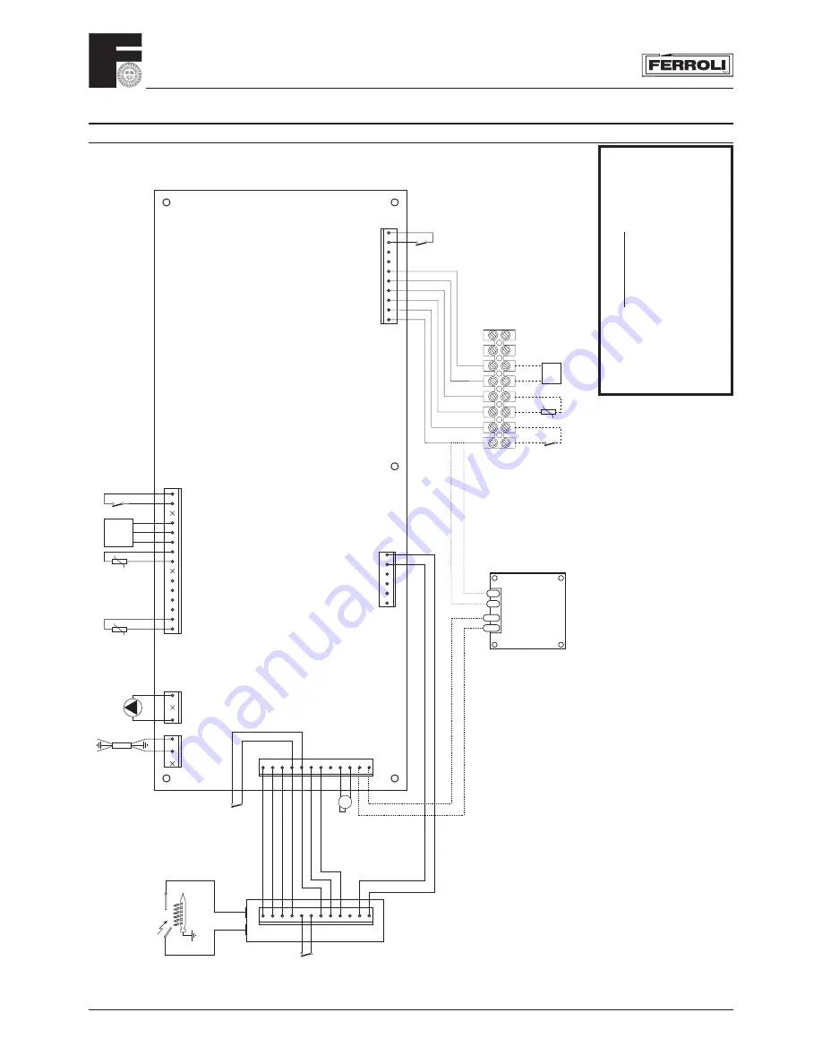
9. ELECTRICAL AND FU NCTIONAL SCHEME
9.01 General wiring diagram
6
58
7
4
3
2
1
12
35
62
10
9
8
7
6
5
4
3
2
1
1
3
1
2
15
14
12
11
10
1
2
4
5
6
7
8
10
11
12
32
+
Output
-
X4
X2
X1
13
14
15
X5
X6
X7
1
2
3
6
7
8
9
10
11
12
DMF03
S4565DM
12
11
10
5
4
3
2
1
NL
4
5
9
8
7
6
230V ~ 50Hz
34
42
136
114
16
81
82
43
NL
13
49
50
72
138
139
Blue
BR
Blue
BR
R
R
Blue
Blue
R
W
G
O
O
BL
BL
W
W
BR
BR
Blue
BR
BR
Blue
BR
R
BL
V
Y
W
BL
BR
BL
BL
BR
Summary of Contents for DOMINA N 80 DGT
Page 12: ...DOMINA N 80 DGT 12 3 01 Boiler Mounting Plate 149 178 131 Fig 13 ...
Page 46: ......
Page 47: ......


