background image

DOMINA N 80 DGT

43

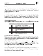
10.02 Ignition

Check than any shut-off valves in the heating system and domestic hot water circuit outside of the boiler 
are open. Open the gas cock upstream from boiler and press the main switch. The boiler will perform an  
self-test cycle lasting approximately one minute, at the end of which it is ready for operation. The ignition and 
shut-down of the burner assembly are completely automatic operations, which depend on the requirements of 
the heating system or domestic hot water circuit.

10.03 Shut-down

In the event of extended periods of inactivity close the gas cock upstream from the boiler and disconnect the 
electrical power supply to the appliance. In this case, the boiler antifreeze protection function is also disabled; this 
function switches on the burner assembly when the heating system temperature falls below 5°C. For extended 
periods of inactivity during the winter months, in order to avoid damage due to freezing, all the water should be 
drained from the boiler, both the domestic hot water and the heating system; alternatively, drain only the domestic 
hot water and introduce the special antifreeze into the heating system.

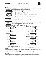
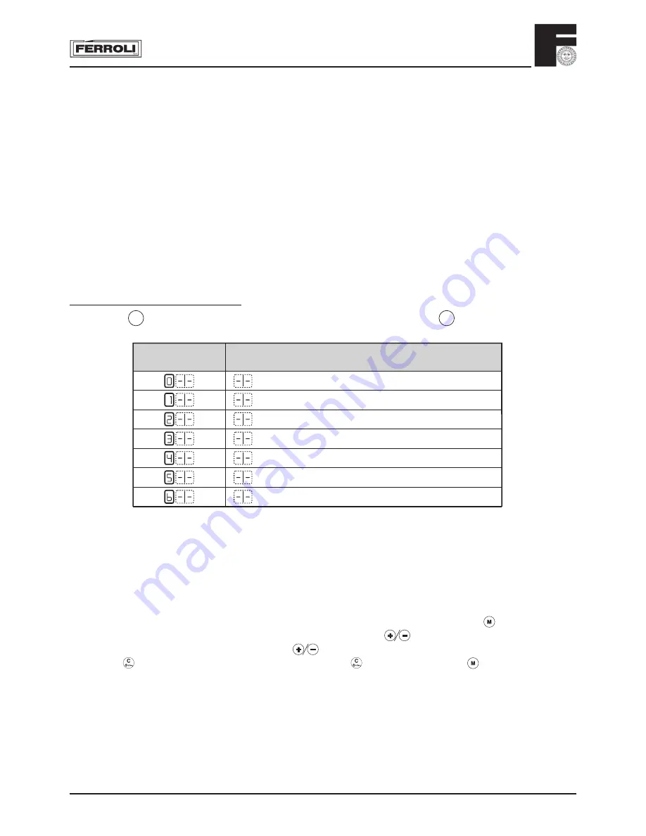
10.04 Accessing the operating menu

Pressing the  M  - mode button once accesses the operating menu. Pressing the  M  mode button again dislays 
the following parameters and information in sequence.

Summer (0) / Winter (1) selection

CH outlet temperature view and setting

Domestic hot water temperature

External temperature

-

Domestic hot water flow rate

Compensation curve setting

DISPLAY D1

DISPLAY D2/D3

10.05 Setting the heating system temperature

Set, using the room thermostat or remote control, the desired temperature inside the rooms. When acting on the 
room thermostat, the boiler is turned on and the heating system water is brought to the central heating outlet set 
temperature or calculated temperature (with temperature scrolling active). On reaching the required temperature 
inside the rooms, the generator will switch off.
If no room thermostat or remote control is installed, the boiler will maintain the heating system temperature 
at the central heating outlet setpoint.
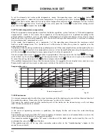
To set the central heating outlet temperature, access the operating menu, and using the  button 

 display parameter 

1 – central heating outlet temperature. On pressing one of the  buttons 

 the display will start to fl ash, showing 

the outlet temperature setpoint. Use the  buttons 

 to set the required value. To activate the new value, press 

the  button 

. To cancel the setting, do not press the  button 

, and press the  button 

.

10.06 Setting the domestic hot water temperature

Set, using the control boiler panel, the required domestic hot water outlet temperature. On opening a hot water 
tap, the system regulates itself to supply water at the set temperature, according to the fl ow rate of delivery 
and the temperature of the cold water supplied to the boiler. If in terms of delivery or temperature difference 
between the inlet and outlet, the thermal capacity of the generator is exceeded (refer to the technical data), the 
outlet temperature will be proportionally lower than the setpoint.

Summary of Contents for DOMINA N 80 DGT

Page 1: ...STALLATION SERVICE AND USER INSTRUCTIONS G C NO 47 267 23 Copper Wall Mounted Combination Gas Fired Boiler for Central Heating and Domestic Hot Water Production Fan Assisted Room Sealed Compartment Electronic Flame Ignition and Control 3543832 1 07 2001 ...

Page 2: ...l be enclosed in your customer information pack This record must be completed and left with the end user All CORGI Registered Installers carry a CORGI ID card and have a registration number Both should be recorded in your central heating log book You can check to the CORGI registered by calling CORGI on 01256 372300 Ferroli is a member of the Benchmark initiative and fully supports the aims of the...

Page 3: ...al heating circuit set to open at 3 bar Built in Expansion vessel Variable speed pump Central heating flow temperature adjustment thermostat Domestic hot water flow temperature adjustment thermostat Central heating limit thermostat Overheat safety thermostat Electronic control unit for automatic flame ignition and control Central heating low water pressure cut off switch Domestic hot water flow te...

Page 4: ...NICAL AND DIMENSIONAL CHARACTERISTICS 2 01 Technical information Domina N 80 DGT boilers are central heating and domestic hot water heat generators and are produced as standard to function with natural gas or Liquid Petrolium Gas converted appliances Key 1 3 4 central heating flow outlet 2 1 2 domestic hot water flow outlet 3 1 2 gas inlet 4 1 2 domestic hot water inlet 5 3 4 central heating retur...

Page 5: ... water heat input Boiler water contents Domestic hot water contents kW kW kW kW kW Litres Litres Domina N 80 DGT 23 8 9 7 25 8 11 5 23 8 1 5 0 8 MODEL Connections Expansion vessel Max working pressure central heating circuit Max working pressure hot water circuit 1 2 3 4 5 Capacity Pre pressurising value Ø Ø Ø Ø Ø Litres bar bar bar Domina N 80 DGT 3 4 1 2 1 2 1 2 3 4 7 1 3 6 MODEL Main injectors ...

Page 6: ...anger 32 Central heating pump 34 Central heating flow temperature sensor 36 Automatic air vent valve 42 Domestic hot water flow temperature sensor Fig 2 43 16 27 50 19 49 28 5 20 21 26 132 90 91 81 82 22 56 IN OUT MIN 10 8 74 7 84 85 44 136 32 36 114 34 14 42 9 11 145 62 43 Air pressure switch 44 Gas valve 49 Safety overheat thermostat 50 Central heating flow limit thermostat 56 Expansion vessel 6...

Page 7: ...as Fig 4 Fig 5 Diagram of pressures and outputs with LPG Propane 2 3 4 5 6 7 8 9 1 0 1 1 1 2 1 3 1 0 1 1 1 2 1 3 1 4 1 5 1 6 1 7 1 8 1 9 2 0 2 1 2 2 2 3 2 4 8 9 1 0 1 1 1 2 1 3 1 4 1 5 1 6 1 7 1 8 1 9 2 0 2 1 kW kcal h x1000 mbar 1 4 kW kcal h X1000 mbar 1 8 1 9 2 0 2 1 2 2 2 3 5 1 0 1 5 2 0 2 5 3 0 3 5 9 1 0 1 1 1 2 1 3 1 4 1 5 1 6 1 7 9 1 0 1 1 1 2 1 3 1 4 1 8 1 9 2 0 1 5 1 6 1 7 8 2 05 Domestic...

Page 8: ... 25 9 55 1 19 0 41 2 33 1 125 17 5 32 4 68 9 23 7 51 5 41 3 150 21 0 38 8 82 6 28 5 61 8 49 6 175 24 5 45 3 96 4 33 2 72 1 57 9 200 28 0 51 8 110 2 38 0 82 4 66 2 0 140 0 259 0 551 0 190 0 412 0 33 For syst volumes other than those given above mult the syst volume by the factor across m h 3 Q 8 7 6 5 4 3 2 1 0 0 5 1 5 2 5 1 2 H mbar x 100 2 06 Pump characteristics The pump head available for circu...

Page 9: ...ich the boiler is installed does not require a purpose provided vent when using the standard concentric flue Flue System The boiler allows the flue outlet to be taken from the rear of the boiler from either side or vertically A standard flue length of 0 75 metres is provided Alternative lengths of two or three metres can be supplied equivalent to wall thicknesses of up to 565 1815 and 2815mm for r...

Page 10: ... for replacing water lost from the sealed system Reference should be made to BS6798 for methods of filling and making up sealed systems There must be no direct connection between the boiler s central heating system and the mains water supply The use of mains water to charge and pressurise the system directly is conditional upon the Local Water Byelaws Again any such connection must be disconnected...

Page 11: ...ve intersection with roof Dimensions Terminal position kW input expressed in net Balanced flues room sealed Open flues Natural draught Natural draught Fanned draught Fanned draught Aa 300 mm 600 mm 1500 mm 2000 mm 300 mm Not allowed 300 mm Ba 300 mm 300 mm 300 mm 600 mm 300 mm Not allowed 300 mm Ca 300 mm 400 mm 600 mm 600 mm 300 mm Not allowed 300 mm D 300 mm 75 mm Not allowed 75 mm E 300 mm 200 ...

Page 12: ...DOMINA N 80 DGT 12 3 01 Boiler Mounting Plate 149 178 131 Fig 13 ...

Page 13: ...wall bracket to the wall using an antitheft nut on the right side and a standard nut M8 on the left side Mount the boiler on the wall bracket and fix using an antitheft nut on the left side and a standard nut M8 on the right side Using a core drill cut a 118mm diameter hole for the flue 1 CH flow 2 Safety Valve 3 Domestic hot water outlet 4 Gas supply 5 Domestic hot water inlet 6 CH return 932 min...

Page 14: ...all bracket to the wall using an antitheft nut on the right side and a standard nut M8 on the left side Mount the boiler on the wall bracket and fix using an antitheft nut on the left side and a standard nut M8 on the right side Using a core drill cut a 118mm diameter hole for the flue 1 CH flow 2 Safety Valve 3 Domestic hot water outlet 4 Gas supply 5 Domestic hot water inlet 6 CH return Fig 15b ...

Page 15: ...all and the plate use the large diameter washers for the bolts and screws Square Gasket Circular Gasket Fig 16e 5 Through plate into air tube drill two holes and fix in place using two self tapping screws M4 x 6mm long 6 Cut the outer flue flush with the flange on the hanging plate Fig 16f 7 Insert the aluminium flue pipe into white plastic outer flue making sure the aluminium pipe sits fully and ...

Page 16: ...ed for top outlet flueing Fig 16h Fig 16i 8 Install the inner metal flue into the outlet up to the wallplate flange mark 9 Lift boiler with flue in place engage inner and outer flue slide into position 9 Make sure the inner flue is fully engaged in the flue terminal secure boiler with two nuts and washers sevure bottom of boiler using two screws and washers b b 1 2 a Take off the four screws which...

Page 17: ...re the seals are in place Fig 17i b b a Fix with the screws b Refit wiring connections to fan and air pressure switch tubes ensuring correct orientation I E red tube to air pressure switch connection with red dot and clear tube to air pressure switch connection with no paint marking Fit the fan into the boiler rotating the front upwards to engage with the pin a Secure with the screws b Fig 17l Fig...

Page 18: ...m maximum mm 0 m 13 m 45 13 m 23 m 47 23 m 38 m 50 38 m 48 m No restrictor With concentric systems Choose correct restrictor from table below With 2 pipe system Calculate the total flow resistance of the air and flue pipes in metres cap 3 08 2 utilise the table shown below to choose the more suitable restrictor for the flow resistance calculated RESTRICTOR FOR CONCENTRIC SYSTEM Flue lenght up to U...

Page 19: ...s an extremely easy and safe option For flue length up to 1 m long the 50 mmØ restrictor is required Longer than this no restrictor is required Fig 19 Concentric Vertical Connector 3 07 2 Horizontal concentric connection A 90 bend fig 20 is supplied for the horizontal connection of air and flue gas pipes This can be oriented towards the chosen wall in degrees of 45 1KWMA31Y D S L 125 70 50 30 95 8...

Page 20: ...n 10 60mm 3 07 3 Maximum concentric flue length First table below shows the maximum flue lengths available for boilers with concentric systems For correct calculation remember to include the reduction for bends on second table Please refer to 3 06 for use of restrictor Maximum flue lenght permissible 100 mm concentric 125 mm concentric Vertical Horizontal Vertical Horizontal Domina N 80 DGT m 4 m ...

Page 21: ...ulation method is based on a standard reference parameter 1 metre of horizontal air flue 80 diameter 80 for the maximum length permissible for all the pipes fittings flow resistance coefficient In other words for all components and pipes in the different installation configurations vertical or horizontal air or flue etc and for all the fittings a flow resistance reduction equivalent to x metre of ...

Page 22: ...ion with split end Ø80 1 1 1 2 1 2 2 2 1 5 2 5 1 5 2 5 7 Reduction 2 4 3 Air Flue Vertical Horizontal Vertical Horizontal 1 2 Condensate flue outlet A c c e s s o r i e s Ø 8 0 A c c e s s o r i e s Ø 8 0 Spigot and socket reduction Ø80 100 0 Reduction Airwall terminal products of combustion Ø80 5 Male female flue Ø100 Male female bend 45 Ø100 Male female bend 90 Ø100 Air wall terminal products of...

Page 23: ...pe system maximum total flue length 48 metres Fig 24 REF N OF PIECES DESCRIPTION CODE LENGTH OR REDUCTION 1 1 Air bend 80 mm R D 0 75 1 5 m 2 13 Horizontal air pipe 13 0 m 3 1 Air wall terminal 2 0 m 4 1 Air inlet closing ßange Ñ 5 1 Flue bend 80 mm R D 0 75 2 5 m 6 12 Horizontal ßue 24 0 m 7 1 Air wall terminal outlet ßue 5 0 m TOTAL 48 0 m Example of wall inlet outlet 2 pipe application Example ...

Page 24: ...2 bars After filling always close and disconnect the filling loop Note If there is a possibility of air pockets forming in certain points of the central heating system flow and return pipes you are recommended to fit an air vent valve at these points Note When the boiler is installed below the level of the central heating a system single check valve should be fitted in the flow to prevent gravity ...

Page 25: ...llows the main burner to ignite only after having verified that the fan is working correctly If the difference in pressure between the flue gas discharge pipe and the air intake pipe is not at least equal to the minimum pressure switch calibration value the pressure switch contacts do not close and the gas valve is thus prevented from opening In addition the electrical circuit of the boiler is des...

Page 26: ...board Remove the connector link from the 2 wires located behind the clock position Connect these to terminal 3 and 5 of the clock Replace everything in reverse order Please refer to page 48 of User manual for use of time clock 6 5 8 7 4 3 2 1 72 10 9 8 7 6 5 4 3 2 1 1 3 1 2 15 14 12 11 10 1 2 4 5 6 7 8 10 11 12 X4 X2 X1 13 14 15 X5 X6 X7 1 2 3 6 7 8 9 10 11 12 DMF03 N L 4 5 13 Fig 30 Wiring for in...

Page 27: ...ral heating Alternatively drain the domestic hot water system only and add special anti freeze to the central heating system 4 04 Checks and controls after first start up Check there are no leaks in the gas and water circuits Check correct boiler start up by carrying out start up and shut down tests using the boiler stat Check the integrity of the air flue pipes during boiler operation Check that ...

Page 28: ...to burner test point B downstream of the gas valve Disconnect the pressre compensation tube F Remove the protective cap C Set boiler on C H Adjust minimum pressure by rotating screw D clockwise to reduce pressure and anticlockwise to increase pressure Activate Test Mode pushing together for 5 sec and on front panel Adjust max presure by rotating screw E clockwise to increase pressure and anticlock...

Page 29: ...er in the central heating system read on the control panel pressure gauge is adjusted as described in paragraph 3 11 page 24 N B To avoid incurring unnecessary expense in the event of boiler shut down check that this is not caused by a lack of electricity or gas or low water pressure before calling the Customer Technical Service Helpline 5 06 Gas conversion The following adjustment and conversion ...

Page 30: ...ull forward 4 Carry out preliminary electrical checks at boiler junction box This is located in the centre of the boiler at the bottom and can be accessed be the removal of a single screw Any faults found must be rectified before proceeding 5 If electrical checks prove O K replace cover and secure with screw 6 Attach a manometer to the boiler gas inlet test point turn on electricty and fire boiler...

Page 31: ...it case and secure with screws 31 Leave boiler set to customers requirements 6 04 Flue Gas Analysis 1 The appliance should be checked visually for obvious defects 2 After removing the jacket on the boiler there are two test point one for flue gas and the other for air 3 Open the air and flue gas test points 4 Introduce the probes as far as the retainer 5 Turn on the hot water tap 6 Turn the domest...

Page 32: ...ondition 7 02 Final procedure Re open cocks and re charge the system to about 1 bar and vent boiler and radiators Re charge to 1 bar if necessary Upon completion of the work the following Should be checked I Gas soundness of all joints II Water soundness of all joints III The electricity supply IV The pressure of the sealed system and top up where necessary 7 03 To lower the control panel fig 34 R...

Page 33: ...or C H Unscrew the sensor Replace in reverse order 7 07 2 Water Pressure Switch fig 38 Isolate electricity and water supplies Remove outer case two screws bottom rear corners Remove the two securing screws and lower control panel Identify the switch from figure 38 Disconnect electrical connections note positions to the switch Drain the boiler Unscrew the sensor Replace in reverse order 7 07 3 Safe...

Page 34: ...Isolate gas and electricity supplies Remove outer case two screws bottom rear corners Remove room sealed cover Disconnect fan electrical leads A and note positions Disconnect air pressure tubes from air pressure switch B note positions Undo two screws securing fan assembly C Remove fan from boiler Swap mounting plate over to new fan replace in reverse order 7 11 Limit thermostat or overheat cut of...

Page 35: ...e heat exchanger close tap Remove outer case two screws bottom rear corners Remove two screws from control panel and tilt forward Take off protective cover from main PCB and unplug flow meter lead from terminal X6 Place a piece of cloth or some other absorbent material over rear of control panel to catch any drops of water that may be released when removing the flow meter Using a 24mm open ended s...

Page 36: ... connecting pipe E from the rear of the pump body by removing the clip from the left hand side Disconnect the boiler return pipe Disconnect the pump to heat exchanger connection by removing the clip F Unscrew the nut on bottom of pump D Turn the pump body through 90 pull the bottom forward and withdraw the pump body Reassemble in reverse order taking care to ensure the O rings are in place and und...

Page 37: ...um effectively bypassing the auto range rating facility Domestic Hot Water Mode External Call for D H W Flow meter registers at least 2 5 litres min flow to the hot water taps Internal Call for D H W Hot water flow temperature sensor 88 C high limit stat and low water pressure switch calling for heat If both internal and external calls are present the boiler follows the same sequence as for C H to...

Page 38: ...iver Check or replace the condenser or the pump Check gas valve Free the pump by removing the cap and rotating the shaft with a screwdriver Check or replace the condenser or the pump Check wiring or replace the sensor Check wiring or replace the sensor Check wiring or replace the sensor Check the correct positionning and operation of the outlet sensor Check the pump 8 03 DMF03 PCB and Diagnostic T...

Page 39: ...H output and maximum D H W temperature adjustable by the controls on the facia and because the boiler features automatic range rating no adjustments need to be made Electro mechanical relays control pump operation and put switched live to the ignition PCB demand relay they have transparent plastic covers so that their contacts can be seen moving 8 08 Air pressure switch Operating at 230 V AC and s...

Page 40: ...LL IRREPARABLY DAMAGE THE ELECTRONIC BOARD 62 Time clock option 72 Room thermostat 81 Ignition electrode 82 Sensor electrode 114 Low water pressure switch 136 Flow meter 138 Outside temperature sensor 139 Room unit 9 ELECTRICAL AND F U NCTIONAL SCHEME 9 01 General wiring diagram 6 5 8 7 4 3 2 1 1 2 3 5 62 10 9 8 7 6 5 4 3 2 1 1 3 1 2 15 14 12 11 10 1 2 4 5 6 7 8 10 11 12 32 Output X 4 X 2 X 1 13 1...

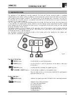
Page 41: ...display provides continuous indication on the operating status of the appliance and can display additional information on the temperature of the sensors the set point etc or be used for the configuration of such via the operating menu using the keypad Any anomalies in operation involving the boiler or the heating system are signalled on the display and where possible corrected automatically MODE b...

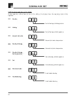
Page 42: ... Central heating outlet temperature Heating Central heating outlet temperature Standby following Domestic hot water temperature domestic hot water Domestic hot water temperature Standby following heating operation Central heating outlet temperature Test Central heating outlet temperature Shut down boiler Code troubleshooting Troubleshooting Code troubleshooting Standby ...

Page 43: ...emperature External temperature Domestic hot water flow rate Compensation curve setting DISPLAY D1 DISPLAY D2 D3 10 05 Setting the heating system temperature Set using the room thermostat or remote control the desired temperature inside the rooms When acting on the room thermostat the boiler is turned on and the heating system water is brought to the central heating outlet set temperature or calcu...

Page 44: ... the user to improve the level of comfort the compensation curve can in fact be modified by accessing the operating menu with the button and scrolling the menu again using the button to parameter 9 The set compensation curve is displayed refer to graph below Pressing one of the buttons the display starts to flash use the buttons to set the required value To activate the new curve press the button ...

Page 45: ...1 Use buttons and to set OFF time eg 9 00 Display 3 1 Use button and to set 2nd ON time eg 12 30 Display 4 1 Use button and to set 2nd OFF time eg 14 00 Display 5 1 Use button and to set 3rd ON time eg 16 00 Display 6 1 Use button and to set 3rd OFF time eg 23 30 Display 8 Oncompletionofprogrammingslideswitch A toAutoposition the time of day will be displayed and the central heating will switch ON...

Page 46: ......

Page 47: ......

Page 48: ...nt Staffordshire DE14 3HD Tel 08707 282 885 Fax 08707 282 886 ALL SPECIFICATIONS SUBJECT TO CHANGE Please note to avoid incurring unnecessary expense in the event of a boiler shut down check this in not caused by lack of electricity supply gas supply or low water pressure before calling our Customer Service Helpline Should you require help with any difficulties call our Technical Service Helpline ...

Reviews: