background image

16

DOMITOP HF 24 - 30 E

FERELLA GOLD HF 24 - 30 MEL

Version  -  09.2002

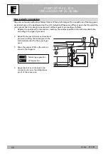
Electrical and plumbing connections

The terminal block for the electrical connections is designed for hooking up the diverter valve and the sensor.

It is necessary to take out the 1.8 KOhm resistor on the probe connection whose job was to simulate a virtual,

always-satisfied boiler.

Boiler connection kit assembly instructions

X4

1

2

3

4

5

6

7

8

9

10

11

12

13

X9

1

2

3

8

7

6

5

4

3

2

1

95

155

A

72

50

114

34

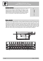
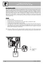
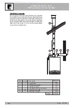
- Connect the pipes and 3-way valve as shown

in Fig. 1.

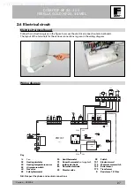
- Make the electrical connection to the terminal

block 

A

 (Fig. 2) as shown in the diagram

Fig. 3.

• Connect the 3-way valve (Ref. 95).
• Connect the boiler sensor (Ref. 155).
• Take out the resistor between terminals 3

and 4.

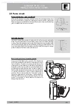
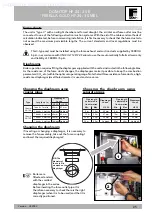
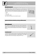
- Open the instrument panel, take out the plug

C

  (Fig.  4)  and  insert  the  knob 

D

  (Fig.  5)

to adjust the tap water temperature.

24  Kw

30  Kw

Fig. 1

Fig. 1

Fig. 2

Fig. 3

Fig. 4

Fig. 5

1KWMK18Y

1KWMK19Y

Supplied by HeatingSpares247.com

Summary of Contents for Domitop HF 24-30 E

Page 1: ...DOMITOP HF 24 30 E FERELLA GOLD HF 24 30 MEL Wall Mounting Gas Boiler Airtight Chamber Heating TECHNICAL MANUAL EDITION 09ï2002 Supplied by HeatingSpares247 com ...

Page 2: ...10 2 Product framework and internal components 11 2 1 Hydraulic circuit heating 11 2 2 Hydraulic circuit tap water via external boiler 15 2 3 Gas circuit 17 2 4 Burner unit 21 2 5 Fume circuit 23 2 6 Electrical circuit 27 3 Operation 30 3 1 Operating principle 30 3 2 Operating diagram 31 3 3 Control panel 32 3 4 Adjustments 32 3 5 Operating parameter adjustment 33 4 Troubleshooting 34 Supplied by ...

Page 3: ...ere are 5 LEDs on the control panel providing information on the unit s operating status General Warnings Installation and maintenance must be carried out by professionally qualified personnel according to current regulations and the manufacturer s instructions Incorrect installation or poor maintenance can cause damage or physical injury The manufacturer declines any responsibility for damage cau...

Page 4: ...nections Domitop HF 24 E version 760 98 155 36 155 460 160 100 25 150 25 84 80 80 120 70 120 150 110 272 249 100 725 114 3 2 1 4 Key 1 System delivery 2 Gas inlet 3 System return 4 System filler inlet Top view Bottomview CONNECTIONS AXIS CONNECTIONS AXIS Supplied by HeatingSpares247 com ...

Page 5: ...02 Ferella Gold HF 24 MEL version Top view Bottom view 1 2 3 1 3 5 4 160 25 150 25 100 271 705 98 155 36 155 114 762 70 120 120 150 460 110 271 80 80 80 Top view 1 System delivery 2 Gas inlet 3 System return 4 System filler inlet Supplied by HeatingSpares247 com ...

Page 6: ... 09 2002 Domitop HF 30 E version Top view Bottom view Key 1 System delivery 2 Gas inlet 3 System return 4 System filler inlet 77 1 2 3 1 2 3 4 155 363 460 692 15 430 15 Ø80 Ø80 Ø80 760 120 120 36 215 54 110 202 110 189 175 Supplied by HeatingSpares247 com ...

Page 7: ...9 2002 Ferella Gold HF 30 MEL version Top view Bottom view 1 2 3 1 3 5 80 80 80 4 15 430 15 362 692 36 155 215 54 189 175 760 110 110 120 120 200 362 460 Key 1 System delivery 2 Gas inlet 3 System return 4 System filler inlet Supplied by HeatingSpares247 com ...

Page 8: ...4 3 Air pressure switch 4 4 Gas valve 4 9 Safety thermostat 5 0 Heatingthermostat 5 6 Expansiontank 6 3 Heating temperature adjustment 7 4 Heating system cock 8 1 Ignition electrode 8 2 Detection electrode 8 4 1st gas valve operator 8 5 2nd gas valve operator 9 8 Off On Reset switch 114 Water pressure switch 145 Water gauge 187 Fume diaphragm 1 3 General view and main components HF 24 E MEL versio...

Page 9: ...ssembly 2 1 Main nozzle 2 2 Burner 2 6 Combustion chamber insulation 2 7 Copperexchanger 2 8 Fume manifold 2 9 Fume outlet manifold 3 2 Heating circulator 3 4 Heating temp sensor 3 6 Automatic air vent 4 3 Air pressure switch 4 4 Gas valve 4 9 Safety thermostat 5 0 Heatingthermostat 5 6 Expansiontank 6 3 Heating temperature adjustment 7 4 Heating system cock 8 1 Ignition electrode 8 2 Detection el...

Page 10: ...IP 44 Electrical power supply Power voltage frequency V Hz 220 50 Max electrical power absorbed W 125 Heating system connection 3 4 Filling system connection 1 2 Gas system connection inches 1 2 Weight with packing kg 35 Heating Natural Gas delivery G20 nm3 h 2 73 1 19 Natural Gas main nozzles G20 mm 12 x 1 30 Pressure at Natural Gas burner G20 mbar 11 8 2 5 Natural Gas supply pressure G20 mbar 20...

Page 11: ...or more details on the operating logic refer to chap 3 Key 5 Airtight chamber 7 Inlet 1 0 System delivery 1 1 System return 1 4 Safety valve 1 6 Fan 2 0 Burner assembly 2 9 Fume outlet manifold 3 2 Heating circulator 3 4 Heating temp sensor 4 3 Air pressure switch 4 4 Gas valve 4 9 Safety thermostat 5 0 Heatingthermostat 5 6 Expansiontank 7 4 Heating system cock 8 1 Ignition electrode 8 2 Detectio...

Page 12: ...eller whichcanbefreedwith the aid of a screwdriver The connection to the expansion tank and the air separator is installed on the pump casing Checks Ifthepumpdoesn twork Checkthattheimpellerisfreetoturnbyturningthescrewonthefrontwith a screwdriver Check that both the card and the pump connection are powered If there is no power supply check the card If there is power change the pump Air separator ...

Page 13: ...heair thetankcompensatesforthethermalexpansionofthewaterintheheatingsystem 30kW 10 litre version 24kW 8 litre version Exchanger The exchanger is a copper laminar assembly It comprises a thickly finned portion and four circular pipes connected together in series The water exchanges directly with the combustion gases and makes the system safe via a safety thermostat 100 C and the limit thermostat 88...

Page 14: ...ingitagainstoverpressure Youarestronglyrecommendednottouse thisvalvetodrainthesystem onceopen dirtcouldremaininsideit preventing itfromclosingcompletely Check valve It ensures the filling system flows only in one direction and remains airtight along with the cock Filler cock Theboilerhasa1 2 connectionontheright handsideoftheheatingdelivery forfillingthesystem Itisnotfittedontheboilerforsomemarket...

Page 15: ...ing the knob included in the kit in the control panel D 43 49 50 56 81 44 32 20 82 222 5 29 187 16 74 14 114 34 7 10 11 VD B E D C F A Key 5 Airtight chamber 7 Inlet 1 0 System delivery 1 1 System return 1 4 Safety valve 1 6 Fan 2 0 Burner assembly 2 9 Fume outlet manifold 3 2 Heating circulator 3 4 Heating temp sensor 4 3 Air pressure switch 4 4 Gas valve 4 9 Safety thermostat 5 0 Heatingthermost...

Page 16: ...instructions X4 1 2 3 4 5 6 7 8 9 10 11 12 13 X9 1 2 3 8 7 6 5 4 3 2 1 95 155 A 72 50 114 34 Connectthepipesand3 wayvalveasshown in Fig 1 Maketheelectricalconnectiontotheterminal block A Fig 2 as shown in the diagram Fig 3 Connect the 3 way valve Ref 95 Connect the boiler sensor Ref 155 Take out the resistor between terminals 3 and 4 Opentheinstrumentpanel takeouttheplug C Fig 4 and insert the kno...

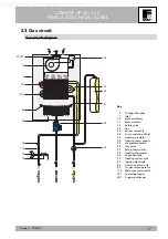
Page 17: ...tem return 1 4 Safety valve 1 6 Fan 2 0 Burner assembly 2 9 Fume outlet manifold 3 2 Heating circulator 3 4 Heating temp sensor 4 3 Air pressure switch 4 4 Gas valve 4 9 Safety thermostat 5 0 Heatingthermostat 5 6 Expansiontank 7 4 Heating system cock 8 1 Ignition electrode 8 2 Detection electrode 8 4 1st gas valve operator 114 Water pressure switch 187 Fume diaphragm 222 Copper exchanger Supplied...

Page 18: ... check there is voltage at the operators This makesitpossibletounderstandwhethertheproblemlieswiththevalve there is voltage at the operators or with the card there is no voltage at thecontactsX6 1 2 3 4 Modulation Thecontrolsystemgovernsitsboilercapacitysoastokeepthedeliverytemperatureconstantinaccordance with the settings on the control panel The nozzle gas pressure is modulated by the valve and ...

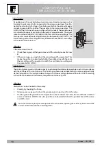
Page 19: ...to maximum anticlockwise Turn on the TEST function by temporarily bridging X5 Adjustthemaximumpressurewiththescrew E clockwise to increase it and anticlockwise to decrease it Reconnectthepressurecompensationtube F Puttheprotectionscrew C backin Disconnectthetestjumper N B The test lasts 5 minutes C F E B A D 25 50V DC COMMON 80 110V DC Key A Pressurepointupstream B Pressurepointdownstream C Protec...

Page 20: ...version kit will be required proceeding as follows 1 Replace the nozzles at the main burner inserting the nozzles specified in the technical data table according to the type of gas used 2 Adjust the burner minimum and maximum pressures setting the values given in the technical data chart for the type of gas used 3 Move the jumper JP02 on the card as shown in the diagram 4 Apply the sticker contain...

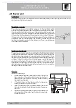
Page 21: ...ion Its base is composed of a ceramic composite of glazed alumina whose purpose is to protect and electrically insulate it Once theignitionprocedurebegins thecardpowerstheelectrodewithapulsating voltage of a few kV a series of electrical discharges is set off between the electrode and the head of the burner set at a distance of 3 5 mm Clearly these sparks are the trigger for the air gas mixture It...

Page 22: ...thofthesingle stages with the contribution of the secondary air from the bottom of the burner mount and from the combustion chamber itself The set of stages in operation forms a single belt of flame light blue in colour whose size varies according to the nozzle gas pressure that is the boiler capacity modulation Detectionelectrode Made of the same material as the ignition electrode it is set 11 mm...

Page 23: ...er is sealed off with a porous plate and is fitted with two plugs for using a probe to analyse the fumes and combustion air Fan and pressure switch points Powered at 230V 50Hz by the card X6 7 8 the fan has the job of expelling the products of combustion from the fume chamber A plate is normally placed above the exchangertoactasadeflector maketheincomingairfrom the bottom of the burner uniform mak...

Page 24: ...e in pressure must drop under 150 13Pa To perform checks on contact opening and closing it is always recommended to check directly on the card X5 3 4 Checks It is necessary to check Whether the electrical connections are correct Whether the pressure test point pipes are clean and contain no condensation water That the signal is open when the fan is not working Thatthepressureisatleast180Paandthata...

Page 25: ...ow resistancefumeducts ahigh resistance diaphragm small hole diameter is used and vice versa Choosing the diaphragm using separate pipes Choosing the diaphragm using coaxial pipes Type Coaxial 60 100 Length up to 1 bend 1 metre 1 bend 3 metres 1 bend 3 metres 1 bend 4 metres 1 bend 5 metres Diaphragm to use 50 mm No diaph 45 mm 50 mm No diaph Coaxial 80 125 HF 24 HF 30 52 mm No diaph 50 mm No diap...

Page 26: ...it If monitoring the condensate trapisnotguaranteed itmustbefittedwithasuitabledrain pipe and air trap which in its turn must be appropriately connected to a suitable drain Ref 1 2 3 4 5 6 No Pieces 1 1 1 1 36 1 Air bend Ø80 Horizontal air pipe Ø80 Windproof end piece Condensate collection cup coupling Vertical fume pipe Ø80 Outlet flue coupling Description Equivalent loss 1 5 m 1 0 m 2 0 m 3 0 m ...

Page 27: ... PMF03F JP02 JP01 JP03 Nat LPG X11 230V 24V 230V 24V BR Blue BR Blue BR Blue MV1 MV2 MV3 MV4 Blue BR Blue BR BR Blue R R O O Blue BR BL BL X9 1 2 3 Blue BR W W 101 L N 8 7 6 5 4 3 2 1 95 155 BL BL Y G Y G R 98 50 114 34 32 44 49 16 43 175 72 Key 16 Fan 32 Heatingcirculator 34 Heatingtemperaturesensor 43 Airpressureswitch 44 Gas valve 49 Safetythermostat 98 Switch 101 Electroniccard 114 Waterpressu...

Page 28: ...scribed hereunder Ignition detection electrode see chap 2 4 Burner Unit Safetythermostat X6 5 6 has a thermostat with gold contacts that opens if the temperature exceeds 100 C Connected directly to the ignition and main card when it opens it cuts off the power supply to the valve directly shutting down the boiler It is located on the left hand side of the exchanger in an appropriate flat seat Limi...

Page 29: ...rature decreases and are connected directly to the main card X4 24V 12 13 The sensorperformstheantifreezefunctiontoo NTC sensor 0 3 6 9 12 15 18 21 24 27 30 33 0 20 40 60 80 100 120 Temperature C Resistance K Ohm 15 50 70 30 90 5 25 40 60 80 100 Temperature C Resistance K Ohm 3 6 1 7 8 0 92 10 5 3 2 5 1 25 0 68 15 6 25 3 Supplied by HeatingSpares247 com ...

Page 30: ...heating mode but idle time and modulation are turned off The test lasts 5 minutes Post circulation Afterthecallforheating thecirculatorperforms post circulation forapproximately6minutestoprevent thermal inertia and balance the system boiler temperature Circulator anti locking If not used for 24 h the circulator is turned on for a few seconds to prevent it locking due to an extended stoppagedurings...

Page 31: ...me detection at ionization electrode within 10 sec safety time End of electric discharge Ionization working range 1 micro Ampere minimum for safety 2 3 micro Ampere minimum for working Ignition gas adjustment natural gas or LPG with potentiometer P4 Heating temperature adjustment trips burner and fan switch off LED 4 off LED 1 off The circulator is working At the end of the 2 min delay the burner ...

Page 32: ...inttemperature The generator turns off when the desired temperature in the rooms is reached Iftheroomthermostatortheremotecontrolarenotinstalledtheboilerwillkeepthesystematthesetsystem deliverysetpointtemperature System temperature adjustment With knob B on the control panel we can set the required system temperature To prevent localized condensation on the fume circuit we recommend a minimum temp...

Page 33: ...LPG P5 Minimumpressureadjustmentpotentiometer The potentiometer P5 is to be used if it is necessary to adjust the minimum current to the second coil of the gas valve This adjustment makes it possible to increase the gas valve minimum opening pressure electrically The potentiometer P5 is used when the mechanical minimum of the gas valve does not enable adequate adjustment Jumper operation JP01 Inse...

Page 34: ...ical connection of the water pressure switch NO Does the burner ignite NO Proceed with diagram 2 NO YES Does the circulator turn If the boiler temperature is under 5 C the antifreeze protection is active NO Check the electrical connection of the circulator Disconnect the heating temperature sensor Is the burner out Check and if necessary change the main card NO NO YES Check and if necessary change...

Page 35: ...ecessary change the pump NO Check the electrical connections of the pump NO YES YES YES YES YES YES Does the fan turn Is the relay RY3 closed Proceed with diagrams 2 3 NO Are there 230V at the fan terminals Check the electrical connection of the air pressure switch NO Check and if necessary change the air pressure switch NO Check and if necessary change the fan Is the air pressure switch activated...

Page 36: ...the ignition card Using P4 adjust the burner ignition pressure Check and if necessary clean the burner Check and if necessary clean the nozzles Check and if necessary clean the detection electrode Check that the ignition electrode is in the right position Check the connections Check and vent the gas supply Check and if necessary change the gas valve NO YES Check and if necessary change the ignitio...

Page 37: ...Supplied by HeatingSpares247 com ...

Page 38: ...Supplied by HeatingSpares247 com ...

Page 39: ...Supplied by HeatingSpares247 com ...

Page 40: ...37047 SAN BONIFACIO VR ITALY tel 045 6139411 tlx 480172 fax 045 6100233 6100933 cod 354M007 0 Supplied by HeatingSpares247 com ...

Reviews: