31
DOMITOP HF 24 - 30 E
FERELLA GOLD HF 24 - 30 MEL
Version - 09.2002
3.2 Operating diagram
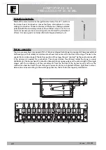
Heating and boiler sensor enabling signal
88°C limit thermostat enabling signal.
Air thermostat "NO" contact open, fan starts.
Intake and outlet ducts open, resistance under table limit.
Pressure difference at air pressure switch >180 Pascal (18.00 mm approx.)
Air pressure switch "NO" contact closed.
100°C safety thermostat enabling signal
Electric discharge to ignition electrode (81).
Continuous voltage of 230 V to the gas valve operators.
Main burner ignition
Flame detection at ionization electrode within 10 sec. (safety time)
End of electric discharge:
Ionization working range
- 1 micro Ampere minimum for safety
- 2/3 micro Ampere minimum for working
Ignition gas adjustment (natural gas or LPG) with potentiometer P4
Heating temperature adjustment trips;
burner and fan switch off
LED 4 off
LED 1 off
The circulator is working
At the end of the 2 min delay, the burner re-ignites
when required
LED 4 on
LED 1 on
Room thermostat trips on reaching the set
temperature:
LED 4 off
LED 1 off
Heating circulator operates for 6 min.
(post-circulation)
System pressure > 0.8 bar:
LED 5 not blinking
Room thermostat, heating potentiometer on call:
LED 4 on
Heating circulator comes on
Winter
Supplied by HeatingSpares247.com

