ECONCEPT 51/51i - 101/101i
53
EN
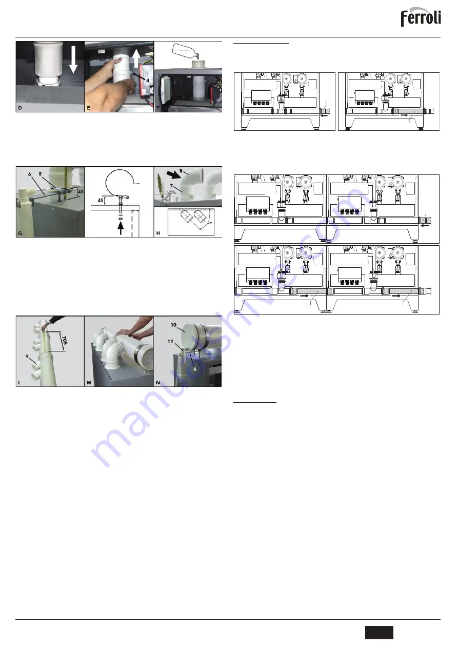
fig. 34
D
Make sure to correctly fit the seals.
E
Lengthen the diameter 100mm extensible part of each valve until it rests
on the inner part of the casing. Fix with the screw
“4”
.
F
Pour 1/2 litre of water on each flue in order to fill the respective traps and
anti-backflow valves. Repeat the above steps for all the flue connections
of the modules.
fig. 35
G
Fit the manifold support flanges
“5“
using the special holes provided on
the top of the modules. The starting bracket on the first module must re-
spect the distance of 45 mm. (see box
“G”
fig. 35). This distance must be
increased by 5 at a time in the following modules, in order to obtain the
fume manifold angle as indicated in fig. 32. Fit the condensate trap “6”
support bracket on the
flange
of the first module.
H
Insert the 90° M-F bends
“8”
on the pipe sections
“7”
, positioning them at
45° with respect to the module (see box
“H”
fig. 35). When installing a
module
ECONCEPT 51/51i
use only one 90° bend and the cap contained
in the starting kit.
fig. 36
L
Fit the flue pipes together (operation to be carried out on the ground) , en-
suring the alignment of the various connections
“9”
and respecting the
coupling measurement of 705 mm (see box
“L”
fig. 36).
M
Place the manifolds connected together on the support flanges and gradually
insert all the bends on the previously fitted diameter 100 pipe sections.
Check the correct angle of the manifold (see fig. 32) and the correct fitting
of all the pipe sections, bends and valves, making sure the seals are prop-
erly fitted (see box
“M”
fig. 36). Make the external seals adhere to the top
of the modules. Tighten and fix the support flanges.
N
Fit the manifold closing cap
“10”
. Insert the condensate trap
“11”
and fix
it to the special bracket
“6”
fitted in point
“G”
. Connect the trap outlet to a
condensate collection point (e.g. the condensate manifold of the modules).
A
Use a special lubricant to facilitate the manifold connections.
3.6 Condensate drain
B
The boiler has an internal condensate drain trap connected to an internal con-
densate outlet manifold.
Condensate drain connection using one generator
fig. 37 - Condensate drain connection with one generator
A
Place the Ø40 pipe 1 (not supplied) on the side of the generator.
B
Slide the pipe 2 towards the side of the arrow for at least 2-3 cm in order to in-
sert it in the pipe 1.
Condensate drain connection using two or more generators
fig. 38 - Condensate drain connection with several generators
A
Place the Ø40 pipe 1 (not supplied) on the side of the generator
B
Slide the pipe 2 (of each generator) towards the side of the arrow for at least 2-
3 cm in order to insert it in the pipe 1.
4. SERVICE AND MAINTENANCE
All adjustment, conversion, commissioning and maintenance operations described be-
low must only be carried out by Qualified Personnel (meeting the professional technical
requirements prescribed by the current regulations) such as those of the Local After-
Sales Technical Service.
FERROLI
declines any liability for damage and/or injury caused by unqualified and un-
authorised persons tampering with the unit.
4.1 Adjustments
Gas conversion
The unit can operate on natural gas or LPG and is factory-set for use with one of these
two gases, as clearly shown on the packing and on the dataplate. Whenever a gas dif-
ferent from that for which the unit is arranged has to be used, a conversion kit will be re-
quired, proceeding as follows:
1.
Open the cabinet of the upper exchange body using the special key supplied.
2.
Loosen the
gas valve fixing ring
"A” .
3.
Undo the three fixing screws
"B"
and remove the gas valve
"C"
.
4.
Replace the gas valve
"D"
with the one contained in the conversion kit, positioning
it
inside the seal
"E” . Refit the parts and check their tightness.
5.
Repeat steps 2, 3 and 4 for the lower exchanger body (model
ECONCEPT 101/
101i
only)
6.
Modify the parameter on the control system.
•
put the boiler in standby mode
•
press the DHW buttons (details 1 and 2 - fig. 1) for 10 seconds. the display
shows "
P01
" flashing.
•
press the DHW buttons (details 1 and 2 - fig. 1
) to set parameter
00 (for use
with natural gas) or
01
(for use with LPG ).
•
press the DHW buttons (details 1 and 2 - fig. 1) for 10 seconds.
•
the boiler will return to standby mode
7.
Apply the label, contained in the conversion kit, near the dataplate.
8.
Using a combustion analyser connected to the boiler fume outlet, make sure the
CO
2
content in the fumes, with the boiler operating at max. and min. output, com-
plies with that given in the technical data table for the corresponding type of gas.
2
B
1
A
2
2
B
A
1
cod. 3540S576 - Rev. 01 - 02/2015
Summary of Contents for ECONCEPT 101
Page 118: ......
Page 119: ......
Page 120: ...FERROLI S p A Via Ritonda 78 a 37047 San Bonifacio Verona ITALY www ferroli it ...


