background image

Econcept 50 A

11

a

aaa

aaa

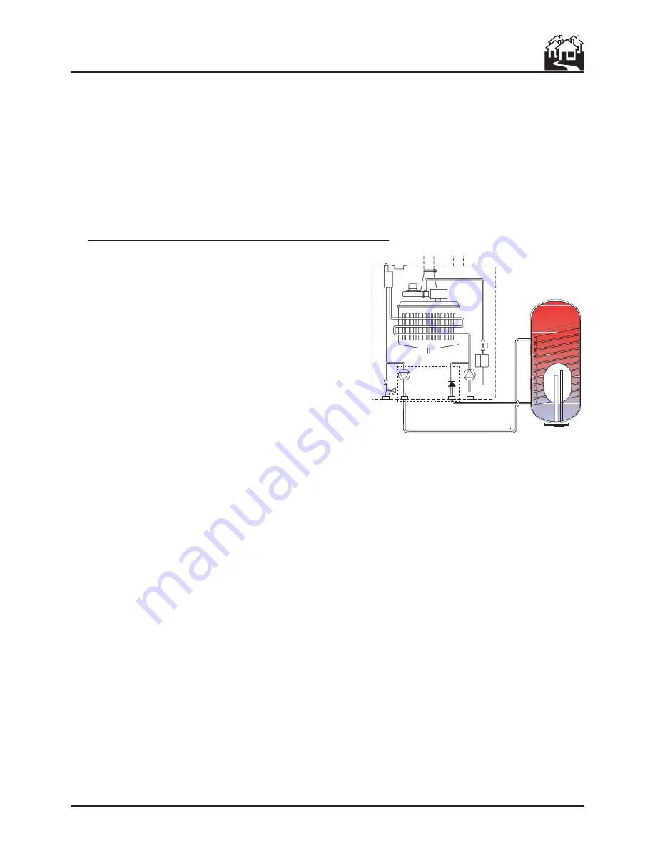
Kit 1KWMH17A

Cylinder not supplied

Fig. 4

DHW calorifier connection(Optional kit 1KWMH17A)

The optional kit 1KWMH17A is available for connection
with an external cylinder. The kit, which includes circulator,
cylinder feeler and hydraulic pipe fittings, has to be mounted
inside the cylinder, according with instruction contained in
the kit itself. Then the connections have to be joined to the
cylinder.

2.4 Connection to the gas system

If necessary the local Gas supplier should be consulted, at
the installation planning stage, in order to establish the
availability of an adequate supply of gas.
An existing service pipe must 

not

 be used without prior

consultation with the Local Gas supplier.
A gas meter can only be connected by the Local Gas
supplier, or by a Local Gas suppliers Contractor.
Installation pipes should be fitted in accordance with
BS6891.
Appliance inlet working pressure must be 20mbar MINIMUM, for NG and 37 mbar minimum for LPG.
Pipework from the meter to the boiler must be of an adequate size.
Do not use pipes of a smaller size than the boiler inlet gas connection.
The complete installation must be tested for gas soundness and purged as described in BS6981.  All pipework
must be adequately supported.  An isolating gas valve should be fitted on the boiler gas inlet. Please wait
10 minutes when lighting from cold before checking gas rate. Gas pressures should be checked after the
boiler has operated for 10 minutes to ensure thermal equilibrium.

Make Up Water

Provision must be made for replacing water lost from the sealed system.  Reference should be made to
BS6798, for methods of filling and making up sealed systems.  There must be no direct connection between
the boiler's central heating system and the mains water supply.  The use of mains water to charge and
pressurise the system directly, is conditional upon the Local Water Byelaws.  Again any such connection must
be disconnected after use.
Always connect and filling device to the return pipework

Summary of Contents for ECONCEPT 50 A

Page 1: ...ECONCEPT 50 A Appr nr B99 15 A CE 0063 BL 3475 cod 3544205 1 ediz 04 2004 WALL HUNG PRE MIX GAS FIRED CONDENSING BOILER INSTALLATION AND OPERATING INSTRUCTIONS ...

Page 2: ...6 modified from the 93 68 INSTRUCTIONS AND REGULATIONS Assembly installation first start up and maintenance must be carried out by competent persons only in accordance with all current technical regulations and directives c o s h h Materials used in the manufacture of this appliance are non hazardous and no special precautions are required when servicing Related Documents This appliance must be in...

Page 3: ...table isolating device In the event of malfunction or faulty operation isolate the appliance Do not attempt to repair or carry out any other operation on the appliance directly Contact qualified personnel only Repairs or the replacement of compo nents must be carried out exclusively by qualified personnel using original spare parts only Failure to respect the above my compromise the safety of the ...

Page 4: ...nnection to the hydraulic system 10 2 4 Connection to the gas system 11 2 5 Electrical connections 12 2 6 Flues 15 2 7 Condensation discharge connection 20 2 8 Modular installation 21 3 SERVICE AND MAINTENANCE 23 3 1 Settings 23 3 2 Commissioning and testing 24 3 3 Maintenance 26 3 4 Troubleshooting 27 4 OPERATING INSTRUCTIONS 29 4 1 Dimensions and connections 29 4 2 General view and main componen...

Page 5: ... interface to simplify Service operations The heat output is regulated continuously across the entire operating range also with DHW storage with temperature scrolling climate control which automatically adapts the operating mode to the characteristics of the internal and external environment of the building and its location using external and internal sensors optional extra 1 2 Boiler control pane...

Page 6: ...lay D2 D3 Central heating outlet temperature Central heating outlet temperature Domestic hot water temperature Domestic hot water temperature Central heating outlet temperature Domestic hot water temperature Operating indications on the display During operation without pressing any of the buttons the display shows the operating status of the appliance Summer Winter Selection 00 Summer 11 Winter Ec...

Page 7: ...point Use the buttons to set the required value To activate the new value press the button To cancel the setting do not press the button and press the button Shut down In the event of extended periods of inactivity close the gas control upstream from the boiler and disconnect the electrical power supply to the appliance In this case the boiler antifreeze protection function is also disabled this f...

Page 8: ...rature of the heating system is regulated according to the external climatic conditions so as to guarantee a high degree of comfort and energy saving all year round Specifically when the external temperature falls the central heating outlet temperature is increased according to a pre determined compensation curve In this mode the temperature set in parameter 1 of the operating menu becomes the max...

Page 9: ...e installed in any room or internal space although particular attention is drawn to the requirements of the current I E E wiring regulations and in Scotland the electrical provisions of the building regulations applicable in Scotland with respect to the installation of the boiler in a room or internal space containing a bath or shower Wherearoomsealedapplianceisinstalledinaroomcontaining a bath or...

Page 10: ...we way Betz Dearborn LTD Croydon surrey CRO 4YS Widnes Cheshire WA8 8ND Tel 0870 5601 5000 Tel 0151 424 5351 Note If the boiler is installed in an existing system any unsuitable additives must be removed by thorough cleasing All systems should be cleansed according to B S 7593 In hard water areas treatment to prevent lime scale may be necessary It is important that the correct concentration of the...

Page 11: ...working pressure must be 20mbar MINIMUM for NG and 37 mbar minimum for LPG Pipework from the meter to the boiler must be of an adequate size Do not use pipes of a smaller size than the boiler inlet gas connection ThecompleteinstallationmustbetestedforgassoundnessandpurgedasdescribedinBS6981 Allpipework must be adequately supported An isolating gas valve should be fitted on the boiler gas inlet Ple...

Page 12: ...Ifthecablegetsdamaged switchoff theunitandhaveitchangedbyaFerroliauthorized Service Centre If changing the electric power cable use solely HAR H05 VV F 3x0 75 mm2 cable with a maximum outside diameter of 8 mm Room thermostat external unit and auxiliary controls Below the electrical control box is a multipolar terminal block for connecting Room thermostat 3 4 WARNING THE ROOM THERMOSTAT MUST NOT HA...

Page 13: ...epend ing on the compensation curve settled ref 1 4 If no probe is connected the boiler works in standard mode and setting of a compensation curve parameter 9 of menu is ignored by the control system External pump 500 It s possible to connect an external pump max 100W to the terminal block Solenoid valve for gas 117 Every times the boiler gas valve opens the circuit board supplies max 20W to the t...

Page 14: ...xternal probe The external probe is best installed on a wall facing north north west or which borders the majority of the main living area The probe must never be exposed to the early morning sun and in general and where possible must not receive direct sunlight if necessary it should be shielded The probe must not in any case be fitted near windows doors ventilation openings flues orsourcesofheat...

Page 15: ... below The second table shows the reductions to be used for any bends in the pipes excluding the initial one Please consider that the horizontal concentric piping must have a slope towards the boiler of at least 3 mm m to allow the condensation which forms in the flues to flow back to the boiler and avoid external dripping The concentric pipes should be sealed with the relative pipe coupling seal ...

Page 16: ...he position of installation of the component itself air intake or flue gas exhaust vertical or horizontal The loss is called equivalent length as it relates to the loss of length in the flue system due to fuctional losses of bends For example a 90 Ø80 bend in flue gas exhaust has a loss equivalent to 2 5 air metres that is equal to 2 5 linear metres of flue pipe 2 Once having completely defined th...

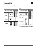
Page 17: ...0 Ø 80 mm Description Airwall terminal products of combustion Ø80 mm Air terminal of inlet protection Ø80 mm Outlet flue air inlet for connection with split end Ø80 mm 0 5 1 0 5 1 0 8 1 6 1 2 1 5 2 0 Reduction KWMA55U 5 2 3 Air Flue Vertical Horizontal Vertical Horizontal Reduction 12 Condensate flue outlet Accessories Ø 80 Accessories Ø 80 Tab 2 The loss values listed refer to original FERROLI pi...

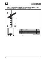
Page 18: ...pe Vertical flue pipe Flue terminal Description Length o loss 19 2 m 12 0 m 12 0 m 43 2 m Total 12 m 1 2 3 Example of how to calculate the connection of two separate pipes max flue length 45 metres The flue and air pipes must be sloped towards the boiler by at least 3 ...

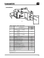
Page 19: ...t e g door window into the dwelling Vertically from a terminal on the same wall Horizontally from a terminal on the same wall From the wall on which the terminal is mounted From a vertical structure on the roof Above intersection with roof Dimensions Terminal position kW input expressed in net Balanced flues room sealed Fanned draught Aa 300 mm Ba 300 mm Ca 300 mm D 75 mm E 200 mm F 200 mm G 150 m...

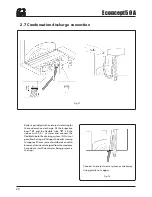
Page 20: ... tube B Fill the siphon with 0 5 l of water and connect the flexibletubetothedrainingsystem Ifthisisnot possible the trap will fill upon the boiler running forapprox20mins careshouldbetakennotto brearanyfumisindischargedfromthecondense hose due to insufficient water being present in the trap Fig 13 Fig 14 Connect to internal waste system or soakaway Using plastic not copper ...

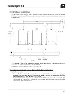
Page 21: ...i piping see page 16 For connection in cascade please observe the following instruction Hydraulic connection Connect all units to a double collector hydraulic circuit one collector for flow one for return or single pipe utilising isolation valves which permit the isolation at each boiler in case of maintenance Distance between module and module D1 must be lower than 0 5 metres Provide safety and p...

Page 22: ...nd electric connections Use theelectroniccontrolbox sequence1KWMH18A optional fortheautomaticmanagementof cascade devices Every control box allow the management from 2 to 5 Econcept boilers in cascade More control boxes can be connected one to another in parallel to allow further expansions 10 15 20 Econcept 50 boilers in cascade For electric connections see the instruction provided in the kit Flu...

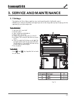
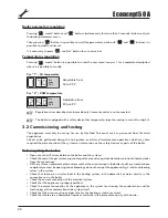
Page 23: ...nversion kit is required 1 Remove jacket 2 Open sealed room department 3 Release A connection 4 Change the injector using the one in the kit 5 Re tighten A and check that there are no gas losses 6 Once the regulation has been made apply the data plate contained in the conversion kit next to the data plate and reassemble the boiler casing and the lower protection plate 7 Run the boiler Test mode Pr...

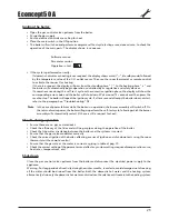
Page 24: ...he first ignition and after all maintenance operations which may have required the disconnection of the systems or intervention on the safety devices or parts of the boiler Before igniting the boiler Open any shut off valves between the boiler and the systems Check the seal of the gas system proceeding with care and using a leak detection solution to find any leaks from the connections Fill the sy...

Page 25: ...efer to the paragraph on Troubleshooting 3 4 Note In the case of power failures while the boiler is in operation the burner assembly will switch off On thereturnofmainspower theboilerwillagainperformthe self testcycle followingwhichtheburner assembly will automatically restart if there is still a request for heat Checks during operation Ensure there are no gas or water leaks Check the efficiency o...

Page 26: ...es The gas and water systems must be perfectly sealed The burner assembly and the heat exchanger must be clean Follow the instructions in the next paragraph The electrodes must be free of deposits and positioned correctly The pressure of the water system when cold must be around 1 1 5 bar if not top up system The expansion vessel must be presurised The circulation and domestic hot water pumps must...

Page 27: ...of the boiler always request the assistance of the service centre Failed burner assembly ignition No gas Ignition or detection electrode fault Defective gas valve Faulty full auto control Check that the gas flow to the boiler is correct and that air has been purged from the piping Check the wiring to the electrodes and that these are positioned correctly and free of deposits Check and replace the ...

Page 28: ...essor operation faulty Disconnect and restore the electrical power supply If the problem persists check and or replace the main board High flue gas temperature 3 x in 24 hours Flue partially blocked or insufficient sized Check the efficiency of the flue the flue gas exhaust pipes and the outlet terminal Excessive central heating outlet temperature Pump blocked Pump faulty Free the pump by removing...

Page 29: ...ECONCEPT 50 A 29 4 TECHNICAL CHARACTERISTICS AND DATA 4 1 Dimensions and connections Key 1 Gas inlet 2 C H flow 3 C H return Fig 17 ...

Page 30: ...Combination gas valve 49 Overheat cut off thermostat 68 Control box with p c b 82 Ionisation electrode 83 Full sequence automatic control 98 Switch 101 Main p c b 114 Low water pressure switch 186 Return temperature sensor 188 Hot surface igniter 191 Exhaust temperature sensor 202 Trasformer 230v 24v 204 PC connector 207 Boiler connector Fig 18 ...

Page 31: ...pressure G20 Natural gas rate G20 Gas Injector G31 Supply pressure G31 LPG gas rate G31 Air Injector Heating Maximum operating pressure Boiler total water content Dimensions weights connections Height Width Depth Weight with packaging Gas system fittings Heating system delivery Heating system return Power supply Max electrical power absorbed Power supply voltage frequency Index of protection kW kW...

Page 32: ...32 Econcept 50 A 4 4 Diagrams 0 0 5 1 1 5 2 2 5 3 3 5 4 0 1 2 3 4 5 6 mc h mt ca 1 2 3 P Fig 19 ...

Page 33: ... 3 2 1 N L 6 5 1 2 3 4 5 6 7 8 9 10 Key 16 Fan 32 Central heating pump 34 C h flow temperature sensor 44 Combination gas valve 49 Overheat cut off thermostat 72 Room thermostat not fitted 82 Ionisation electrode 83 Full sequence automatic control 98 Switch 101 Main p c b 104 Fuse 114 Water pressure switch 117 Opening solenoid valve for gas max 20W 130 D h w pump optional 138 Outside temperature se...

Page 34: ......

Page 35: ......

Page 36: ...NSTANT ENDEAVOUR FOR IMPROVEMENT DETAILS MAY VARY SLIGHTLY FROM THOSE QUOTED IN THESE INSTRUCTIONS Please note to avoid incurring unnecessary expense in the event of a boiler shut down check this in not caused by lack of electricity supply gas supply or low water pressure before calling our Customer Service Helpline Should you require help with any difficulties call our Technical Service Helpline ...

Reviews: