ECONCEPT 50 A
33
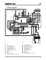
4.5 Wiring diagrams
1
2
3 4 5
6
7 8
10 11 12
14 15
X6
1
2
5
6
7 8
9 10
12 11 10
9
8
7
6
5
4
3
2
3
4
11 12
1
2
3 4 5
6
7 8
10 11 12
9
83
82
188
186
P
114
34
130
15 14 13 12 11 10
8 7
6
5
4
2
1
X5
X7
104
4,0 A
T
X3
N
L
2
3
X2
N
L
N
L
2
3
1
1
X1
DMF04
101
104
2 A
T
X4
207
1
2
3
4
5
6
7
8
9
10
11
12
202
230V
L
N
24V
r
p
o w
24VDC +
FREQ
PWM OUT
24VDC -
w o p r
230 V 50Hz
16
155
139
1,8 k
Ω
10 k
Ω
+/- 5VDC 24VAC
72
T
191
98
N
L
32
138
49
203
117
244
500
4
3
2
1
N
L
6
5
1
2
3
4
5
6
7
8
9
10
Key
16
Fan
32
Central heating pump
34
C.h. flow temperature sensor
44
Combination gas valve
49
Overheat cut-off thermostat
72
Room thermostat (not fitted)
82
Ionisation electrode
83
Full sequence automatic control
98
Switch
101
Main p.c.b.
104
Fuse
114
Water pressure switch
117
Opening solenoid valve for gas (max 20W)
130
D.h.w. pump (optional)
138
Outside temperature sensor
139
Room unit (optional)
155
Storage tank sensor (optional)
186
Return temperature sensor
188
Hot surface igniter
191
Exhaust temperature sensor
202
Transformer 230v-24v
203
230v
204
PC connector
207
Boiler connector
500
External pump (100W - not provided)
Fig. 20

