background image

Optimax 25 OV

14

Central heating request

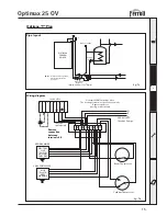
The heat demand can be done by the room thermostat (terminal 4-5) or by a switch line phase 230 V 
(terminal 4).

Standard Systems

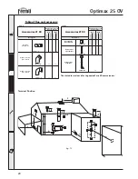
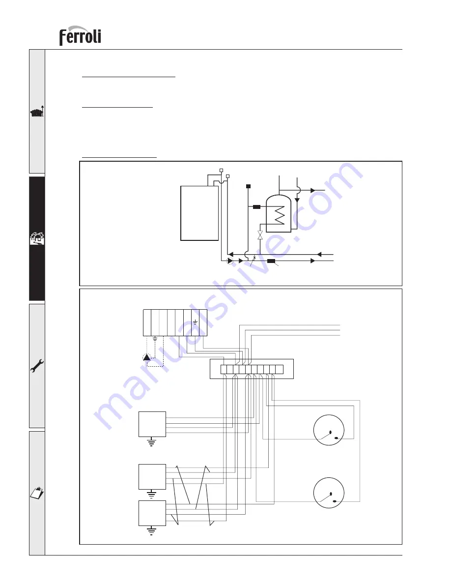
For a general pipe layout and wiring diagram on the “S” and “Y” plan systems please see fi g. 
6a, 6b,  and 7a, 7b.

OPTIMAX “S” Plan

Pipe layout

Wiring diagram

OPTIMAX

FERROLI

BOILER

Balancing

valve

C.H.

Zone Valve

Automatic

bypass

(mimimum flow of 6l/min.)

A.A.V

A.A.V

DHW

zone

valve

*Note:

cold feed and expansion

not shown for clarity

(see fig. 5)

Auto air vent

4

3

2

1

Junction Box

N E

L

Terminal 4
SWITCH LINE

1 2 3 4 5 6 7 8 9 10

PROGRAMMER

DHW ON

CH ON

NEUTRAL

LIVE

CH

zone

valve

DHW

zone

valve

Room Thermostat

Cylinder Thermostat

N
E
L

230 Volt A/C

fused at

3 amps

BROWN

BLUE

GREY

ORANGE

L

7

6

5

8

Fig. 6a

Fig. 6b

Remove 
connection 
between 
terminals 4-5

Summary of Contents for OPTIMAX 25 OV

Page 1: ...OPTIMAX 25 OV wall mounting pre mixed condensing gas boiler INSTRUCTIONS FOR USE INSTALLATION AND MAINTENANCE cod 3544708 3 08 2004...

Page 2: ...orfaultyoperation switch off the appliance Do not attempt to repair or carry out any other operation on the appliance directly Contact qualified personnel only Repairs or the replacement of components...

Page 3: ...nections 10 2 4 Connection to the gas system 13 2 5 Electrical Connections 13 2 6 Flue system 16 2 7 Condensate outlet connection 22 3 SERVICE AND MAINTENANCE 24 3 1 Adjustments 24 3 2 System start up...

Page 4: ...ealed from the installation room the air needed for combustion is drawn from outside The boiler also includes a modulating speed fan modulating gas valve safety valve temperature sensors a safety ther...

Page 5: ...g the key down for at least 5 seconds turns off the boiler To turn it back on press the key again for 5 seconds Pressing the key resets boiler operation after a lock out Pressing the key 3 times withi...

Page 6: ...ature Summer Winter selection To select Summer Winter use knob 1 fig 1 Turning it onto Summer turns off the heating function but the frost protection stays active Turning it onto Winter turns on heati...

Page 7: ...the fault code There are some faults that will require the end user to press RESET 2 fig 1 if the boiler fails to start It is necessary to rectify the fault indicated by the LED display faults from 1...

Page 8: ...ry for which the manufacturer declines any responsibility This appliance must be installed strictly in accordance with these instruc tions and regulations The Gas Safety Regulations Installations Use...

Page 9: ...required by the EEC Directive no 90 396 for all gas units including those with a so called sealed chamber Therefore the place of installation must be free of dust flammable materials or objects or co...

Page 10: ...e lowest point in the system to allow its complete emptying when required The temperature differential between the flow and the return to the boiler should not exceed 20 C 11 recommended Do not use th...

Page 11: ...up of water must be made via a suitably sized cold feed and expansion tank installed to the current regulations This appliance is not suitable for gravity type installations or primatic type cylinders...

Page 12: ...rain Flow Return Open Vent Open Vent Motorised valve 22 mm DHW Isolating valve CH Pump Automatic By pass Motorised valve 22 mm CH Radiator Radiator Balancing valve 15 mm 22 mm Indirect cylinder Indire...

Page 13: ...for gas soundness and purged as described in BS689 All pipework must be adquately supported An isolating gas valve is provided and should be fitted on the boiler gas inlet Please wait 10 minutes when...

Page 14: ...g diagram OPTIMAX FERROLI BOILER Balancing valve C H Zone Valve Automatic bypass mimimum flow of 6l min A A V A A V DHW zone valve Note cold feed and expansion not shown for clarity see fig 5 Auto air...

Page 15: ...diagram 4 3 2 1 Junction Box N L 1 2 3 4 5 6 7 8 9 10 PROGRAMMER NEUTRAL LIVE CH ON DHW ON DHW OFF BLUE WHITE GREY ORANGE Room Thermostat Cylinder Thermostat N E L 240 Volt A C fused at 3 amps Honeyw...

Page 16: ...fig 8 The layout of the terminals for the various connections is given in the wiring diagram in fig 9 below 2 6 Flue system The unit is type C with a sealed chamber and forced draught the air inlet an...

Page 17: ...S D 205 mm Horizontal flue installation 1 Define the position for installing the unit 2 If using standard flue 1KWMR53A this must be installed level for non standard flue lenghts over 1mtr a fall of 3...

Page 18: ...installing the unit 2 Drillthewallfortheair fluepipeoutletaccor ding to the references stated in the table considering that the horizontal sections of piping must have a gradient of approxima tely 3 m...

Page 19: ...ation before installation 1 For each component tables 4 5 provide an equivalent load loss in linear metres depending on the position of installation of the component with air suction or flue extractio...

Page 20: ...e female Description Horozontial flue terminal Horozontial air terminal Vertical flue terminal 1 1 1 6 2 1 2 1 8 1 5 2 0 Equivalent losses in metres linear 5 2 Air Flue Vertical Horizontal Vertical Ho...

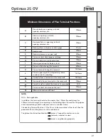
Page 21: ...on the same wall Vertically from a terminal on the same wall From an opening in the car port e g door window into the dwelling Above ground roof or balcony level 300mm 300mm 300mm 200mm 75mm 200mm 15...

Page 22: ...missible with a vertical progression and with no constrictions Have the flue conveying the hot fumes adequately distanced or isolated from combustible mate rials Be connected to just one unit per floo...

Page 23: ...Where it is not possible to terminate internally the condensate discharge pipe may be run outside see below drawing Any external run is subjet to freezing in severe weather conditions To avoid this th...

Page 24: ...or LPG and is factory set for use with one of the two gases as clearly shown on the packing and on the unit s dataplate Whenever a different gas to that for which the unit is preset has to be used a...

Page 25: ...cally whenever the external controls call for heating In case of an electrical power failure while the boiler is working the burner will go out When power returns the boiler will run the self test cyc...

Page 26: ...and safety devices gas valve thermostats etc must function correctly The flue terminal end piece and ducts must be free of obstructions and leaks The gas and water systems must be sound The burner and...

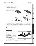
Page 27: ...leaks Combustion analysis It is possible to analyse the combustion through the air and fume sampling points shown in fig 18 To make the measurement it is necessary to 1 Open the air and fume sampling...

Page 28: ...he wiring Check the components Change the valve F9 Microprocessor trouble Microprocessor operating trouble Cut off and restore the electricity supply If the trouble remains check and or change the mai...

Page 29: ...ult Check the electrical system F35 Electronic PCB trouble F36 Change the electronic CVBC F43 Sensor damaged or wiring shorted Check the wiring or change the sensor Return sensor fault F44 Sensor dama...

Page 30: ...4 TECHNICAL CHARACTERISTICS AND DATA 4 1 Dimensions and connections fig 19 Top view Bottom view 50 35 35 45 164 201 35 400 95 120 185 50 1 3 1 3 164 2 274 2 4 Key 1 CH flow 2 Gas inlet 3 CH return 4...

Page 31: ...irtight chamber 7 Gas inlet 10 CH flow 11 CH return 16 Premix fan 19 Combustion chamber 21 Gas injector 22 Ceramic burner 29 Flue outlet manifold 34 Heating flow sensor 44 Gas valve 49 Safety thermost...

Page 32: ...6 161 201 4 3 Hydraulic diagram fig 21 Key 7 Gas inlet 10 CH flow 11 CH return 16 Premix fan assembly 34 Flow temperature sensor 44 Gas valve 49 Safety thermostat 154 Condensate outlet pipe 161 Heat e...

Page 33: ...power supply Max electrical power absorbed W 30 90 3 0 8 8 1 1 7 720 400 358 34 22 22 75 50 Powers Hi Heating power Natural Gas delivery G20 Natural Gas supply pressure G20 LPG flow rate G31 LPG suppl...

Page 34: ...CPD5 1 32 X3 X6 X1 X7 X5 X2 1 2 3 4 5 6 7 8 9 10 1 2 3 4 6 7 8 5 GND 16 1 2 3 4 TACHO PWM 24V 8 7 6 5 4 3 2 1 Remove if external control fitted 230Vac 4 5 Wiring diagram fig 22 Key 16 Fan 32 Central h...

Page 35: ......

Page 36: ...5 Fax 08707 282 886 ALL SPECIFICATIONS SUBJECT TO CHANGE Please note to avoid incurring unnecessary expense in the event of a boiler shut down check this is not caused by lack of electricity supply ga...

Reviews: