Optimax 25 OV
31
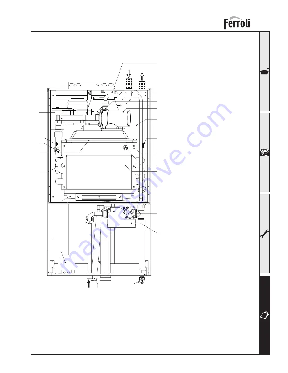
4.2 General view and main components
fi g. 20
5
21
Flue gas sensor
201
82
188
19
44
83
Viewing window
186
29
10
11
196
161
22
49
34
16
175
7 154
Drain off valve
Key
5 Airtight chamber
7 Gas inlet
10 CH fl ow
11 CH return
16 Premix fan
19 Combustion chamber
21 Gas injector
22 Ceramic burner
29 Flue outlet manifold
34 Heating fl ow sensor
44 Gas valve
49 Safety thermostat
82 Ionisation probe
83 C.V.B.C unit
154 Condensate outlet pipe
161 Heat exchanger
175 Transformer
186 Return sensor
188 Ignition electrode
196 Condensate collector
201 Fan Venturi
Summary of Contents for OPTIMAX 25 OV
Page 35: ......


