background image

OPTIMAX HE 31 S

14

Cod. 3540F441 - 03/2007  (Rev. 01)

fig. 13

The user must never change the unit’s power cable. If the cable gets damaged, switch off the unit 
and have it changed only by professionally qualified personnel. If changing the electric power cable, 
use only 

“HAR H05 VV-F”

 3x0.75 mm

2

  cable with a maximum outside diameter of 8 mm.

Access to the electrical terminal block

Follow the instructions given in fig. 13 to access the electrical connection terminal block. The layout of 
the terminals for the various connections is given in the wiring diagram in the Technical Data chapter.

Key

62

  Time Clock (optional)

fig. 14

Room thermostat 

Remove connections 5 - 6 if external control fitted.
If using external controls the switched line can be connected into terminal 5 of the electrical 
block ( see fig 15 and 16 ).

Warning: the 
room thermo-
stat works at 
230V

Summary of Contents for OPTIMAX HE 31 S

Page 1: ...INSTRUCTIONS FOR USE INSTALLATION AND MAINTENANCE FOR THE UNITED KINGDOM AND EIRE OPTIMAX HE 31 S wall mounted gas fired pre mix condensing system boiler cod 3540F441 04 2007 Rev 01 G C No 41 267 26...

Page 2: ...is considered improper and therefore dan gerous Incorrect installation and use or failure to follow the instructions provided by the manufacturer absolve the manufacturer from all liability for damag...

Page 3: ...r connections 11 2 4 Connection to the gas system 13 2 5 Electrical Connections 13 2 6 Flue system 16 2 7 Condensate outlet connection 22 3 SERVICE AND MAINTENANCE 24 3 1 Adjustments 24 3 2 System sta...

Page 4: ...is totally room sealed from the installation room the air needed for combustion is drawn from outside The boiler also includes a modulating speed fan modulating gas valve pump expansion vessel safety...

Page 5: ...point increasing push button 5 Display LCD 6 Reset 7 On Off push button 8 Domestic Hot Water symbol 11 Multi function indication 12 Degrees indication 13 Central Heating mode operation 14 Central Heat...

Page 6: ...the Air purge function During the first 5 seconds the display shows the software version of the pcb Open the gas cock on the boiler and purge the air from the pipework upstream of the gas valve When...

Page 7: ...essure bar 10 The boiler is ready to function automatically whenever the external controls are calling for heat eco comfort reset fig 7 1 4 Adjustments Heating temperature setting To set the system fl...

Page 8: ...n must be reset manually by pressing the reset Part 6 fig 1 for 1 second Other faults F indication cause temporary shutdowns that are automatically reset as soon as the value causing the fault comes b...

Page 9: ...NS AND REFERENCE SHOULD BE MADE TO THE CURRENT ETCI RULES FOR ELEC TRICAL INSTALLATIONS Incorrect installation can cause damage or physical injury for which the manufacturer declines any re sponsibili...

Page 10: ...ll The wall fixing must ensure a stable and effective support for the appliance using the bracket and fixings supplied If the unit is enclosed in a cupboard or moun ted alongside there must be space f...

Page 11: ...ovide this flow rate in most circumstances Do not use the water system pipes to earth electrical appliances Before installation carefully flush all the pipes of the heating system to remove residues o...

Page 12: ...from the sealed system Reference should be made to BS6798 for methods of filling and making up sealed systems There must be no direct connection between the boiler s central heating system and the ma...

Page 13: ...If the boiler is installed on an existing system any unsuitable additives must be removed by tho rough cleansing All systems should be cleansed according to B S 7593 Note In hard water areas treatmen...

Page 14: ...of 8 mm Access to the electrical terminal block Follow the instructions given in fig 13 to access the electrical connection terminal block The layout of the terminals for the various connections is g...

Page 15: ...and Y plan systems please see fig 15a 15b and 16a 16b OPTIMAX S Plan Wiring diagram OPTIMAX FERROLI BOILER D H W Zone Valve C H Zone Valve Auto air vent 4 3 2 1 Junction Box N E L Terminal 5 SWITCH L...

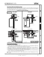
Page 16: ...ink between terminals 5 6 Pipe layout 2 6 Flue system The unit is type C with a sealed chamber and forced draught the air inlet and flue outlet must be connected to one of the following flue systems W...

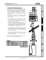
Page 17: ...able on request to meet the various installation requirements Please refer to our flue manual or the price list Standard concentric flue installation Horizontal flue installation 1 Define the position...

Page 18: ...1KWMA71W 2 Use the required amount of 1mtr flue extensions part number 1KWMA56U inserting them spigot down ensuring the seals are well lubricated with silicone grease not supplied and correctly locate...

Page 19: ...loss in linear metres depending on the position of installation of the component with air intake or flue extraction vertical or horizontal Thelossiscalled equivalentlength sinceitiscompared to the lo...

Page 20: ...scription Horizontal flue terminal Horizontal air terminal Vertical flue terminal 1 1 1 6 2 1 2 1 8 1 5 2 0 Equivalent losses in metres linear 5 2 Air Flue Vertical Horizontal Vertical Horizontal Equi...

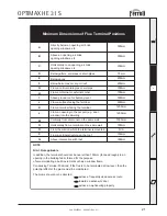
Page 21: ...orizontally from a terminal on the same wall Vertically from a terminal on the same wall From an opening in the car port e g door window into the dwelling Above ground roof or balcony level 300mm 300m...

Page 22: ...ible with a vertical progression and with no constrictions Have the flue conveying the hot fumes adequately distanced or isolated from combustible mate rials Be connected to just one unit per floor fo...

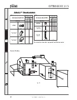
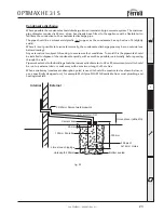
Page 23: ...s the condensate has a ph value of 4 slightly acidic Where it is not possible to terminate internally the condensate discharge pipe may be run outside see below drawing Any external run is subject to...

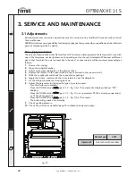
Page 24: ...d a conversion kit will be required proceeding as follows 1 Remove the casing 2 Open the airtight chamber 3 Unscrew the gas coupling A on the air gas mixer 4 Replace the injector in the mixer with the...

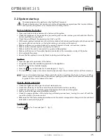
Page 25: ...spin the pump Ensure the flue system is correctly fitted including terminal locations Ignition Open the gas valve upstream of the boiler Purge the air from the installation pipework to the appliance S...

Page 26: ...inal end piece and ducts must be free of obstructions and leaks The gas and water systems must be sound The burner and exchanger must be clean The electrodes must be free of scale and correctly positi...

Page 27: ...the sealed chamber gaskets cable clamps etc In addition it is necessary to pay attention after performing all these operations to check and carry out all the phases of ignition and thermostat operatio...

Page 28: ...de wiring Main board defective Check the PCB A03 High limit protection Flow sensor not active or correctly located Check the correct positioning and operation of the flow sensor No system circulation...

Page 29: ...nterrupted fan connection Check the wiring and fan Fan damaged debris in fan Check the fan clean debris F34 Supply voltage under 180V Electric mains fault Check the electrical system F35 Irregular mai...

Page 30: ...outlet Key 1 System flow 22 mm with isolation valve fitted 3 Gas inlet 22 mm with isolation valve fitted 5 System return 22 mm with isolation valve fitted c w filter 3 4 3 4 1 2 1 3 6 5 7 112 120 120...

Page 31: ...29 Flue Collar 32 Pump 36 Automatic air vent 44 Gas valve 56 Expansion vessel 82 Ionisation electrode 145 System pressure gauge 154 Condensate outlet pipe 161 Heat exchanger 186 Return sensor 188 Ign...

Page 32: ...4 16 Key 7 Gas inlet 10 CH flow 11 CH return 14 Pressure Relief valve 16 Premix fan assembly 32 Pump 36 Automatic air vent 44 Gas valve 56 Expansion vessel 154 Condensate outlet pipe 161 Heat exchange...

Page 33: ...ctrical power supply Max electrical power absorbed W Electric power drawn by the circulator Speed I II III W 20 90 95 3 0 8 9 1 2 700 450 330 43 22 22 95 130 60 65 75 Output max min CH Heat input Natu...

Page 34: ...HE 31 S 34 Cod 3540F441 03 2007 Rev 01 4 5 Diagrams Head available for the system fig 29 0 1 2 3 4 5 6 7 0 500 1 000 1 500 2 000 Q l h H m H2O A 3 1 2 Key 1 2 3 Pump selector positions A Boiler losses...

Page 35: ...ve 62 Time clock optional 81 Spark Electrode 82 Ionisation electrode 101 Main p c b 103 Relay 104 Fuse 186 Return temperature sensor 191 Exhaust temperature sensor 202 Transformer 230V 24V 203 Supply...

Page 36: ......
Page 37: ...ED FOR THE DOMESTIC HOT WATER MODE MEASURE RECORD GAS RATE ft3 hr MAXIMUM BURNER OPERATING PRESSURE IF APPLICABLE mbar COLD WATER INLET TEMPERATURE C HOT WATER OUTLET TEMPERATURE C WATER FLOW RATE lts...

Page 38: ...TS SIGNATURE SERVICE 3 DATE ENGINEER NAME COMPANY NAME TEL No CORGI ID CARD SERIAL No COMMENTS SIGNATURE SERVICE 4 DATE ENGINEER NAME COMPANY NAME TEL No CORGI ID CARD SERIAL No COMMENTS SIGNATURE SER...

Page 39: ...ore calling our Customer Service Helpline Lichfield Road Branston Industrial Estate Burton Upon Trent Staffordshire DE14 3HD Tel 08707 282 885 Fax 08707 282 886 EIRE only HEATOVENT Greenhills Industri...

Reviews: