OPTIMAX HE 31 S
15
Cod. 3540F441 - 03/2007 (Rev. 01)
Central heating Demand
The heat demand can be controlled by the room thermostat (terminal 5-6) or by a switch line 230 V
(terminal 5).
Standard Systems
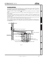
For a general pipe layout and wiring diagram on the “S” and “Y” plan systems please see fig.
15a, 15b, and 16a, 16b.
OPTIMAX “S” Plan
Wiring diagram
OPTIMAX
FERROLI
BOILER
D.H.W.
Zone Valve
C.H.
Zone Valve
Auto air vent
4 3 2 1
Junction Box
N E L
Terminal 5 - SWITCH LINE
1 2 3 4 5 6 7 8 9 10
PROGRAMMER
DHW ON
CH ON
NEUTRAL
LIVE
CH
zone
valve
DHW
zone
valve
Room Thermostat
Cylinder Thermostat
N
E
L
230 Vac
fused at
3 amps
BROWN
BLUE
GREY
ORANGE
L
6 5
Fig. 15a
Fig. 15b
Remove
Link
between
terminals 5-6
Pipe layout
Summary of Contents for OPTIMAX HE 31 S
Page 36: ......


