background image

PEGASUS D 30 K 100 LN

38

EN

3. INSTALLATION
3.1 General Instructions

BOILER INSTALLATION MUST ONLY BE PERFORMED BY QUALIFIED PERSON-
NEL, IN ACCORDANCE WITH ALL THE INSTRUCTIONS GIVEN IN THIS TECHNICAL
MANUAL, THE PROVISIONS OF CURRENT LAW, THE PRESCRIPTIONS OF NA-
TIONAL AND LOCAL STANDARDS AND THE RULES OF PROPER WORKMANSHIP.

3.2 Place of installation

The boiler unit must be installed in a specific room with ventilation openings to the out-
side as prescribed by current regulations. If there are several burners or suction units
that can work together in the same room, the ventilation openings must be sized for si-
multaneous operation of all the units. The place of installation must be free of flammable
materials or objects, corrosive gases, powders or volatile substances that, conveyed by
the burner fan, can obstruct the internal lines of the burner or the combustion head. The
room must be dry and not exposed to rain, snow or frost.

A

If the unit is enclosed in a cabinet or mounted alongside, a space must be pro-
vided for removing the casing and for normal maintenance operations.

3.3 Plumbing connections

The heating capacity of the unit must be previously established by calculating the build-
ing's heat requirement according to current regulations. The system must be provided
with all the components for correct and regular operation. It is advisable to install on-off
valves between the boiler and heating system allowing the boiler to be isolated from the
system if necessary.

B

The safety valve outlet must be connected to a funnel or collection pipe to pre-
vent water spurting onto the floor in case of overpressure in the heating circuit.
Otherwise, if the discharge valve cuts in and floods the room, the boiler manu-
facturer cannot be held liable.
Do not use the water system pipes to earth electrical appliances.

Before installation, carefully wash all the pipes of the system to remove any residuals or
impurities that could affect proper operation of the unit.
Carry out the relevant connections according to the diagram in cap. 5.1 and the symbols
given on the unit.

Water system characteristics

In the presence of water harder than 25° Fr (1°F = 10ppm CaCO3), use suitably treated
water in order to avoid possible scaling in the boiler. Treatment must not reduce the hard-
ness to values below 15°F (Decree 236/88 for uses of water intended for human con-
sumption). Treatment of the water used is indispensable in case of very large systems
or with frequent introduction of replenishing water in the system.

B

If water softeners are installed at the boiler cold water inlet, make sure not to
reduce the water hardness too much, as this could cause early deterioration of
the magnesium anode in the hot water tank.

Antifreeze system, antifreeze fluids, additives and inhibitors

The boiler is equipped with an antifreeze system that turns on the boiler in heating mode
when the system delivery water temperature falls under 6°C. The device will not come
on if the electricity and/or gas supply to the unit are cut off. If it becomes necessary, it is
permissible to use antifreeze fluid, additives and inhibitors only if the manufacturer of
these fluids or additives guarantees they are suitable for this use and cause no damage
to the heat exchanger or other components and/or materials of the boiler unit and sys-
tem. It is prohibited to use generic antifreeze fluid, additives or inhibitors that are not ex-
pressly suited for use in heating systems and compatible with the materials of the boiler
unit and system.

3.4 Gas connection

B

Before making the connection, make sure the unit is arranged for operation with
the type of fuel available and carefully clean all the system gas pipes to remove
any residuals or impurities that could affect proper operation of the boiler.

The gas must be connected to the respective union (see fig. 25) in conformity with cur-
rent regulations, with a rigid metal pipe or with a continuous surface flexible s/steel tube,
installing a gas cock between the system and boiler. Make sure all the gas connections
are tight.
The capacity of the gas meter must be sufficient for the simultaneous use of all the ap-
pliances connected to it. The diameter of the gas pipe leaving the boiler does not deter-
mine the diameter of the pipe between the unit and the meter; it must be chosen
according to its length and pressure losses, in conformity with the current regulations.

B

Do not use the gas pipes to earth electrical appliances.

3.5 Electrical connections
Connection to the electrical grid

B

The unit's electrical safety is only guaranteed when correctly connected to an
efficient earthing system executed according to current safety standards. Have
the efficiency and suitability of the earthing system checked by professionally
qualified personnel. The manufacturer is not responsible for any damage
caused by failure to earth the system. Also make sure that the electrical system
is adequate for the maximum power absorbed by the unit, as specified on the
boiler dataplate.

The boiler is prewired and provided with a Y-cable and plug for connection to the elec-
tricity line. The connections to the grid must be made with a permanent connection and
equipped with a bipolar switch whose contacts have a minimum opening of at least 3
mm, interposing fuses of max. 3A between the boiler and the line. It is important to re-
spect the polarities (LINE: brown wire / NEUTRAL: blue wire / EARTH:  yellow-green
wire) in making connections to the electrical line. During installation or when changing
the power cable, the earth wire must be left 2 cm longer than the others.

B

The user must never change the unit's power cable. If the cable gets damaged,
switch off the unit and have it changed solely by professionally qualified person-
nel. If changing the electric power cable, use solely 

“HAR H05 VV-F”

 3x0.75

mm2 cable with a maximum outside diameter of 8 mm.

Room thermostat (optional)

B

IMPORTANT: THE ROOM THERMOSTAT MUST HAVE VOLTAGE-FREE
CONTACTS. CONNECTING 230 V TO THE ROOM THERMOSTAT TERMI-
NALS WILL PERMANENTLY DAMAGE THE ELECTRONIC BOARD.
When connecting time controls or a timer, do not take the power supply for
these devices from their breaking contacts Their power supply must be by
means of direct connection from the mains or with batteries, depending on the
kind of device.

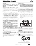
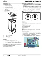
Accessing the electrical terminal block

Undo the two screws 

“A”

 located on the top part of the control panel and remove the

cover.

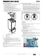
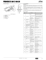
fig. 17 - Accessing the terminal board

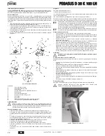
3.6 Connection to the flue

The flue connection pipe diameter must not be less than that of the connection on the
anti-backflow device. Starting from the anti-backflow device it must have a vertical sec-
tion at least 50 cm long. Comply with the current standards regarding installation and siz-
es of the flues and connection pipe.
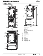
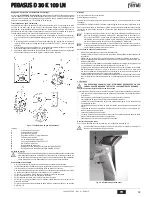
The diameter of the anti-backflow device collar is given in fig. 27.

4. SERVICE AND MAINTENANCE
4.1 Adjustments

All adjustment and conversion operations must be carried out by Qualified Personnel.
The manufacturer declines any liability for damage and/or injury caused by unqualified
and unauthorised persons tampering with the unit.

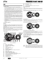
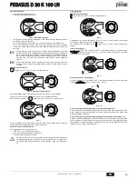
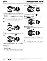
TEST mode activation

Press the heating buttons 

 (part. 3 and 4 - fig. 1) at the same time for 5 sec-

onds to activate 

TEST

 mode. The boiler lights at maximum power.

The heating symbol (detail 24 - fig. 1) and DHW symbol (detail 12 - fig. 1) flash on the
display.

fig. 18 - Operation in TEST mode

To deactivate TEST mode, repeat the activation sequence.
In any case, TEST mode is automatically deactivated after 15 minutes.

A

eco

comfort

m

o

d

e

r e s et

eco

bar

cod. 3540T306  -  Rev. 01 - 02/2015

Summary of Contents for PEGASUS D 30 K 100 LN

Page 1: ...E E LA MANUTENZIONE ES INSTRUCCIONES DE USO INSTALACI N Y MANTENIMIENTO TR KULLANMA KURULUM VE BAK M TALIMATLAR EN INSTRUCTIONS FOR USE INSTALLATION AND MAINTENANCE FR INSTRUCTIONS D UTILISATION D INS...

Page 2: ...impostazione temperatura acqua calda sanitaria 3 Tasto decremento impostazione temperatura impianto riscaldamento 4 Tasto incremento impostazione temperatura impianto riscaldamento 5 Display 6 Tasto s...

Page 3: ...netto del gas a monte della caldaia Togliere alimentazione elettrica all apparecchio B Per lunghe soste durante il periodo invernale al fine di evitare danni dovuti al gelo consigliabile far scaricare...

Page 4: ...amento parallelo delle curve di compensazione Regolazioni da Cronocomando Remoto A Se alla caldaia collegato il Cronocomando Remoto opzionale le regolazioni descritte in precedenza vengono gestite sec...

Page 5: ...ffettuare una ac curata pulizia di tutte le tubature gas dell impianto per rimuovere eventuali re sidui che potrebbero compromettere il buon funzionamento della caldaia L allacciamento gas deve essere...

Page 6: ...la valvola gas fig 19 Accensione Aprire le valvole di intercettazione combustibile Fornire l alimentazione elettrica all apparecchio Per i successivi 120 secondi il display visualizza FH che identific...

Page 7: ...lmeno una volta all anno Se l acqua presenta un forte valore di durezza superiore a 20 gradi francesi installare nell impianto un dolcificatore d acqua Svuotamento del bollitore e dell impianto di ris...

Page 8: ...ne impedito per 20 minuti Contatto termostato fumi aperto Verificare il termostato Cablaggio interrotto Verificare il cablaggio Camino non correttamente dimensionato oppure ostruito Sostituire la cann...

Page 9: ...Termostato regolazione bollitore 178 Bulbo termometro bollitore 179 Valvola di non ritorno 180 Bollitore 192 Ricircolo 197 Sfiato aria manuale 209 Mandata bollitore 210 Ritorno bollitore 233 Rubinett...

Page 10: ...iaframma Pressione gas max al bruciatore G31 mbar 35 Portata gas max G31 kg h 2 52 Pressione max esercizio riscaldamento bar 6 PMS Pressione min esercizio riscaldamento bar 0 8 Temperatura max riscald...

Page 11: ...81 Elettrodo d accensione 82 Elettrodo rilevazione 126 Termostato fumi 130 Circolatore bollitore 138 Sonda esterna 139 Unit ambiente 246 Trasduttore di pressione 278 Sensore doppio Sicurezza Riscaldam...

Page 12: ...portatenelpresenteCer cato Gliinterven ingaranzianon modi cano la data di decorrenza della garanzia e non prolungano la durata della stessa Esclusioni Sono esclusi dalla presente garanzia i dife di co...

Page 13: ...ura de calefacci n 5 Pantalla 6 Tecla para seleccionar el modo Verano Invierno 7 Tecla para seleccionar el modo Economy Comfort 8 Tecla de rearme reset 9 Tecla para encender apagar el equipo 10 Tecla...

Page 14: ...tes de la caldera Desconectar el aparato B Si se desea apagar la caldera por mucho tiempo durante el invierno para evitar da os causados por las heladas es aconsejable descargar toda el agua de la cal...

Page 15: ...or a distancia opcional los ajustes descritos anteriormente se gestionan seg n lo indicado en la tabla 1 Adem s en la pantalla del panel de mandos 5 fig 1 aparece la temperatura ambiente actual medida...

Page 16: ...bustible disponible y limpiar esmeradamente to dos los tubos del gas para eliminar residuos que puedan perjudicar el funcio namiento de la caldera El gas se ha de conectar al correspondiente empalme v...

Page 17: ...aparato Durante los 120 segundos siguientes en la pantalla aparece el mensaje FH que identifica el ciclo de purga de aire de la instalaci n de calefacci n Durante los primeros 5 segundos en la pantall...

Page 18: ...aciar el acumulador Se aconseja efectuar este control una vez al a o como m nimo Si la dureza del agua supera los 20 F montar un descalcificador en la instalaci n Vaciado del acumulador y de la calefa...

Page 19: ...o de humos abierto Controlar el termostato Cableado interrumpido Controlar el cableado Chimenea mal dimensio nada u obstruida Sustituir la chimenea A06 No hay llama tras la fase de encendido Baja pres...

Page 20: ...ador 143 Termostato regulaci n acumulador 178 Bulbo term metro acumulador 179 V lvula antirretorno 180 Acumulador 192 Recirculaci n 197 Purgador de aire manual 209 Ida a acumulador 210 Retorno de acum...

Page 21: ...diafragma Presi n m xima quemador con G31 mbar 35 Caudal m ximo G31 kg h 2 52 Presi n m xima funcionamiento calefacci n bar 6 PMS Presi n m nima funcionamiento calefacci n bar 0 8 Temperatura m xima a...

Page 22: ...ectrodo de detecci n 126 Termostato de los humos 130 Bomba de circulaci n acumulador 138 Sonda externa 139 Unidad de ambiente 246 Transductor de presi n 278 Sensor doble Seguridad Calefacci n DSP05 7...

Page 23: ...la cumplimentaci n de la totalidad de los datos en el Certi cado de Funcionamiento La cumplimenta ci n del certi cado deber realizarse inmediatamente a la P M y consignar la fecha correctamente envi...

Page 24: ...ayar n art rma tu u 3 Is tma sisteminin s ayar n azaltma tu u 4 Is tma sisteminin s ayar n art rma tu u 5 G sterge 6 Yaz K modu se im tu u 7 Ekonomi Konfor modu se im tu u 8 Resetleme tu u 9 Cihaz al...

Page 25: ...muslu unu kapat n z Cihaz n elektrik beslemesini kesiniz B K mevsiminde uzunca s re boyunca kombinin kapal kalmas durumunda donmadan korumak i in kombideki t m suyun musluk suyu ve sistem suyu nun tah...

Page 26: ...14 Kompenzasyon e rilerinin paralel hareketine rnek Uzaktan kumanda ile ayarlamalar A E er kombiye bir Uzaktan Kumanda opsiyonel tak l ise nceki k s mda a klanan ayarlamalar tabella 1 belirtilen de er...

Page 27: ...a gaz sisteminin b t n borular n dikkatlice temizleyiniz Gaz y r rl kteki standartlara uygun olarak ilgili bulunan konnekt re bkz ek 25 sert metal borular ile veya devaml esnek s elik duvar boru tesis...

Page 28: ...e leme Yak t a ma kapama valf n a n z Cihaz n elektrik beslemesini a n z 120 Saniye boyunca g sterge ekran nda s tma sisteminin hava bo altma i lemini belir ten FH mesaj g r nt lenir lk 5 saniye s res...

Page 29: ...ktan sonra 233 ek 25 bo alt m muslu unu kullan n z bu i lem i in bir s cak su ekme noktas kullan n z evye du vb Is tma sistemini tamamen bo altmak i in ek 25179 par a no lu geri d n s z ek 25iki valf...

Page 30: ...sisat n kontrol ediniz Bacan n ebatlar yanl t r veya t kal durumdad r Duman kanal n de i tiriniz A06 Ate leme a amas ndan sonra alev yetersizli i Gaz sisteminde d k bas n Gaz bas nc n kontrol ediniz B...

Page 31: ...n sirk lat r 143 Kazan ayar termostat 178 Kazan termometre haznesi 179 Geri d n s z valf 180 Kazan 192 Devir daim 197 Manuel hava tahliyesi 209 Kazan k 210 Kazan giri i 233 Kazan bo altma muslu u 246...

Page 32: ...s z Br l r maks gaz bas nc G31 mbar 35 Maks gaz kapasitesi G31 Kg s 2 52 Is tmada maks al ma bas nc bar 6 PMS Is tmada min al ma bas nc bar 0 8 Is tma maks s cakl C 95 tmax Is tma suyu kapasitesi litr...

Page 33: ...126 Duman termostat 130 Kazan sirk lat r 138 Harici sonda 139 Ortam nitesi 246 Bas n d r c 278 ift sens r Emniyet Is tma DSP05 7 6 5 4 3 2 1 11 10 9 8 7 6 5 4 3 2 1 T1 T2 X7 7 6 5 4 3 2 1 6 5 4 3 2 1...

Page 34: ...le s n rl d r 7 Cihaz n kullanma k lavuzunda yer alan hususlara ayk r kullan lmas ndan kaynaklanan ar zalar garanti kapsam d ndad r 8 Garanti belgesi ile ilgili olarak kabilecek sorunlar i in Sanayi v...

Page 35: ...ncrease button 3 Heating system temperature setting decrease button 4 Heating system temperature setting increase button 5 Display 6 Summer Winter mode selection button 7 Economy Comfort mode selectio...

Page 36: ...ock ahead of the boiler Disconnect the power supply to the unit B To avoid damage caused by freezing during long idle periods in winter it is ad visable to drain all water from the boiler and system o...

Page 37: ...ve shift Adjustments from Remote Timer Control A If the Remote Timer Control optional is connected to the boiler the above ad justments are managed according to that given in table 1 Also the control...

Page 38: ...to remove any residuals or impurities that could affect proper operation of the boiler The gas must be connected to the respective union see fig 25 in conformity with cur rent regulations with a rigid...

Page 39: ...ng Open the fuel on off valves Connect the power to the unit For the next 120 seconds the display will show FH which identifies the heating system air venting cycle During the first 5 seconds the disp...

Page 40: ...se the drain cock 233 of fig 25 after closing the valves for filling from the water system use a hot water drawing point washbasin shower etc as a vent To drain the heating system completely use the c...

Page 41: ...r the fume ther mostat activation boiler operation is prevented for 20 minutes Fume thermostat contact open Check the thermostat Wiring disconnected Check the wiring Flue not correctly sized or obstru...

Page 42: ...Hot water tank control thermostat 178 Hot water tank thermometer bulb 179 Non return valve 180 Hot water tank 192 Recirculation 197 Manual air vent 209 Hot water tank delivery 210 Hot water tank retur...

Page 43: ...ssure at burner G31 mbar 35 Max gas delivery G31 kg h 2 52 Max working pressure in heating bar 6 PMS Min working pressure in heating bar 0 8 Max heating temperature C 95 tmax Heating water content L 1...

Page 44: ...hermostat 130 Hot water tank circulating pump 138 External probe 139 Room unit 246 Pressure transducer 278 Double sensor Safety Heating DSP05 7 6 5 4 3 2 1 11 10 9 8 7 6 5 4 3 2 1 T1 T2 X7 7 6 5 4 3 2...

Page 45: ...nitaire 3 Touche pour diminuer le r glage de la temp rature de l installation de chauffa ge 4 Touche pour augmenter le r glage de la temp rature de l installation de chauf fage 5 Afficheur 6 Touche de...

Page 46: ...9 fig 1 Fermer le robinet des gaz en amont de la chaudi re Mettre hors tension l appareil B Pour les arr ts prolong s en p riode hivernale et afin d viter les dommages caus s par le gel il est conseil...

Page 47: ...haudi re est reli e la chronocommande distance option les r gla ges ci dessus seront g r s comme indiqu dans le tableau tableau 1 En outre sur l afficheur du tableau des commandes rep 5 fig 1 appara t...

Page 48: ...type de combustible disponible et prendre soin de bien net toyer les conduites du circuit afin d en retirer tout r sidu pouvant compromettre le bon fonctionnement de la chaudi re Le raccordement au ga...

Page 49: ...pareil sous tension Pendant les 120 secondes qui suivent l afficheur visualise FH cycle de purge de l air du circuit de chauffage Pendant les 5 premi res secondes l afficheur visualise galement la ver...

Page 50: ...de remplissage du r seau de distribution Utiliser comme vent un point de pr l vement d eau chaude vier douche etc Pour vider compl tement l installation de chauffage utiliser le robinet 275 fig 25 apr...

Page 51: ...tiv pendant 20 minutes Contact de thermostat s cu rit fum es ouvert V rifier le thermostat C blage interrompu V rifier le c blage Conduit de chemin e non correctement dimensionn ou obstru Remplacer le...

Page 52: ...0 Circulateur ballon 143 Thermostat de r glage du ballon 178 Sonde thermom tre ballon 179 Clapet anti retour 180 Ballon 192 Recirculation 197 vent air manuel 209 Refoulement ballon 210 Retour ballon 2...

Page 53: ...sion gaz maxi au br leur G31 mbar 35 D bit gaz puissance maxi G31 kg h 02 52 Pression maxi d utilisation chauffage bar 6 PMS Pression mini d utilisation chauffage bar 0 8 Temp rature maxi chauffage C...

Page 54: ...n 126 Thermostat s curit fum es 130 Circulateur ballon 138 Sonde externe 139 Unit ambiante 246 Transducteur de pression 278 Capteur double s curit chauffage DSP05 7 6 5 4 3 2 1 11 10 9 8 7 6 5 4 3 2 1...

Page 55: ...5 26 27 24 25 1 26 1 2 Comfort 12 13 1 Comfort 15 1 11 1 3 conomy COMFORT 15 1 ECO 15 1 ECO eco comfort 7 1 COMFORT eco comfort 7 1 2 3 4 B sez 3 3 eco comfort m o d e r e s e t ecomfort bar 5 7 9 10...

Page 56: ...1 8 27 1 6 1 1 30 C 85 C 1 3 4 45 C 9 10 C 65 C 1 2 1 10 eco comfort m o d e r e s e t eco comfort m o d e r e s e t eco comfort m o d e r e s e t eco bar eco comfort m o d e r e s e t eco bar eco com...

Page 57: ...1 0 16 A 120 FH 1 16 20 30 40 50 60 70 80 90 85 20 10 0 10 20 1 2 3 4 5 6 8 9 10 7 20 30 40 50 60 70 80 90 85 20 10 0 10 20 1 2 3 4 5 6 8 9 10 7 20 10 0 10 20 20 30 40 50 60 70 80 90 85 1 2 3 4 5 6 8...

Page 58: ...B cap 5 1 25 Fr 1 F 10 CaCO3 15 F 236 88 B 6 C 3 4 B 25 B 3 5 B Y 3 3A 2 B HAR H05 VV F 3x0 75 2 8 B 230 A 17 3 6 0 5 27 4 4 1 TEST 3 4 1 5 TEST 24 1 12 1 18 TEST TEST TEST 15 A eco comfort m o d e r...

Page 59: ...ASUS D 30 K 100 LN sez 5 3 6 19 G20 G31 1 cap 5 3 2 3 19 G20 G31 3 4 19 1 2 3 4 5 6 A Honeywell VK 4100 C 1075 B C D G20 G25 E G30 G31 4 2 B 1 19 120 FH 5 FH A A01 15 RESET A cap 5 3 t 4 3 B 24 1 20 B...

Page 60: ...SUS D 30 K 100 LN 60 RU 21 21 1 2 3 4 5 6 7 2 3 6 21 4 21 20 25233 275 25 179 25 22 255 25 179 25 197 25 A 179 25 22 A B 7 21 1 2 3 4 5 TEST 6 10 15 7 A 23 23 4 3 2 1 5 7 6 A B cod 3540T306 Rev 01 02...

Page 61: ...PEGASUS D 30 K 100 LN 61 RU 24 1 2 3 4 5 6 7 4 4 22 1 A RESET 8 1 1 RESET F 2 A01 A02 A03 F04 20 A06 F10 1 F11 F14 2 F34 170 F35 F37 F39 F40 A41 F42 F47 cod 3540T306 Rev 01 02 2015...

Page 62: ...130 143 178 179 180 192 197 209 210 233 246 255 273 275 278 293 A48 A49 197 246 32 179 130 143 178 97 180 275 44 255 293 233 500 36 273 40 74 750 140 197 36 11 10 179 209 192 210 278 i 131 40 52 82 1...

Page 63: ...EC NOx 5 G20 x 3 x 2 90 G20 20 G20 4 8 G20 16 G20 3 3 41 G31 x 3x1 65 G31 37 G31 G31 35 G31 2 52 6 PMS 0 8 C 95 tmax L 12 5 L 10 1 9 0 1 L 100 L 4 3 Dt 30 C 10 10 220 Dt 30 C 800 IP X0D 230 50 110 90...

Page 64: ...9 246 278 DSP05 7 6 5 4 3 2 1 11 10 9 8 7 6 5 4 3 2 1 T1 T2 X7 7 6 5 4 3 2 1 6 5 4 3 2 1 X5 F1 F2 X1 X2 X4 X3 X6 X8 X10 2 1 T T 278 GND 5V OUT 246 L N 230V 50Hz 138 139 72 L N 4 5 6 7 8 9 10 11 12 13...

Page 65: ...i 20 21 22 23 i i i 24 25 26 i i i i 27 i i i i 24 25 1 26 1 2 i 12 13 1 i 15 1 11 1 3 i i i i i i i COMFORT 15 1 i ECO 15 1 ECO eco comfort 7 1 i COMFORT i eco comfort i 7 1 2 3 4 B i i i sez 3 3 eco...

Page 66: ...i i i i 2 4 i 6 1 1 8 i 27 1 i i 6 1 1 3 4 1 i i i i 30 C 85 C i 45 C 9 1 2 1 10 C 65 C 10 i i i eco comfort m o d e r e s e t eco comfort m o d e r e s e t eco comfort m o d e r e s e t eco bar eco...

Page 67: ...i i i i 1 i 1 0 i i i i i F37 15 15 i i 1 16 i i 1 0 16 A i i i i 120 FH 1 16 20 30 40 50 60 70 80 90 85 20 10 0 10 20 1 2 3 4 5 6 8 9 10 7 20 30 40 50 60 70 80 90 85 20 10 0 10 20 1 2 3 4 5 6 8 9 10...

Page 68: ...B i i i i i i 6 C 3 4 B i i i i i i i i i i i i i i i 25 i i i i i i i i i i i i i i i i i i i i i i i i i i i i i i B 3 5 B Y 3 2 B HAR H05 VV F 3x0 75 2 8 i i B I I I I 230 I i i i i i i i i i i i A...

Page 69: ...5 6 A Honeywell VK 4100 C 1075 B i D G20 G25 E I G30 G31 4 2 B i i i i i i i i i i i i i i i i i i i i i i i i i 1 19 i i i i 120 FH i 5 i FH A i i i 01 i 15 i RESET i i i A cap 5 3 i t i i i i i i i...

Page 70: ...i i i i i i i i 4 21 i i i 20 i i i i i i 233 25 i i i i i 275 25 i i 179 25 22 i i i i i i i i i i i i i i i i 255 25 i 179 25 i i i 197 25 A i i i i 179 25 22 A B i i i i i i 7 21 1 i i 2 i i i i 3...

Page 71: ...i i i i i A i RESET 8 1 1 RESET i i i i F 2 i A01 i i A02 i i A03 i i F04 i i i i i 20 i i i A06 i i i i i i i i i i F10 1 F11 F14 2 F34 170 i i i F35 i i i i F37 i i F39 i i i i i F40 i i A41 i i i i...

Page 72: ...74 97 130 i 143 178 179 180 192 i 197 209 i i 210 i i 233 246 255 i i 273 i 275 278 i 293 197 246 32 179 130 143 178 97 180 275 44 255 293 233 500 36 273 40 74 750 140 197 36 11 10 179 209 192 210 278...

Page 73: ...C NOx 5 G20 x 3 x 2 90 G20 20 i G20 4 8 G20 16 G20 3 3 41 G31 x 3x1 65 G31 37 i G31 G31 35 G31 2 52 i 6 PMS i i i 0 8 C 95 tmax 12 5 i 10 1 9 i i 0 1 i 100 i 4 3 i Dt 30 C 10 10 220 i Dt 30 C 10 800 I...

Page 74: ...9 246 278 i DSP05 7 6 5 4 3 2 1 11 10 9 8 7 6 5 4 3 2 1 T1 T2 X7 7 6 5 4 3 2 1 6 5 4 3 2 1 X5 F1 F2 X1 X2 X4 X3 X6 X8 X10 2 1 T T 278 GND 5V OUT 246 L N 230V 50Hz 138 139 72 L N 4 5 6 7 8 9 10 11 12 1...

Page 75: ...sione Direttiva Compatibilit Elettromagnetica Presidente e Legale rappresentante Cav del Lavoro Dante Ferroli IT Uygunluk beyani malat i FERROLI S p A Adres Via Ritonda 78 a 37047 San Bonifacio VR bu...

Page 76: ...Bonifacio VR CEE 2009 142 92 42 Dante Ferroli RU D claration de conformit Le constructeur FERROLI S p A Adresse Via Ritonda 78 a 37047 San Bonifacio VR d clare que cet appareil est conforme aux direct...

Reviews: