Rendimax N EL
22
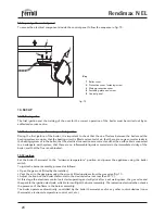
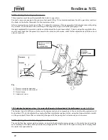
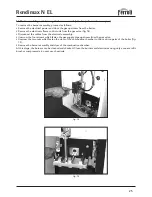
Key
1
Pressure test point upstream
2
Pressure test point downstream
3
Protective cap
4
Adjustment screw
fig. 11
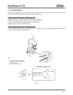
11.04 adjusting the heating system _t by varying the fl ow-rate discharge head of the built-in pump
(models 16-23-30 pv)
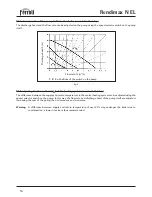
The thermal head
∆
t (difference between the supply and return temperature in the central heating system) must
be less than 20°c, and is adjusted by varying the flow-rate/discharge head of the, using the 3-speed selector switch
on the pump itself. Note that on increasing the speed of the pump, the
∆
t decreases, and vice-versa.
11.05 adjusting the central heating system water pressure
The central heating system water pressure, as read on the thermal pressure gauge on the control panel, must be
set according to the instructions provided in paragraph 8.06. In the case of an open vessel system, simply check
the water level periodically.
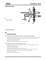
Decrease
Increase
11.03 adjusting the heating system power
This procedure must be performed with the boiler in operation.
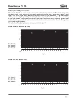
Connect a pressure gauge to the pressure test point 2 (fig. 11) located downstream from the gas valve, and turn
the knob on the boiler thermostat to the maximum value.
After removing the protective cap 3 (fig. 11), adjust the pressure of the gas supplied to the burner assembly, using
the screw 4, to the desired value, referring to the diagrams in figs. 4a and 4b, paragraph 7.02.
Having completed this operation, ignite and shut-down the burner assembly 2, 3 times, using the regulation ther-
mostat, and check that the pressure is equal to the set value; otherwise, make further adjustments until the correct
value is reached.
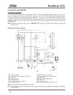
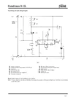
Electronic Control Unit
Honeywell
S 4565 AD 2056
Gas valve
Honeywell
VK 4105 C 1009
1
2
3
4

