Rendimax N EL
6
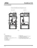
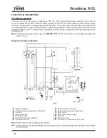
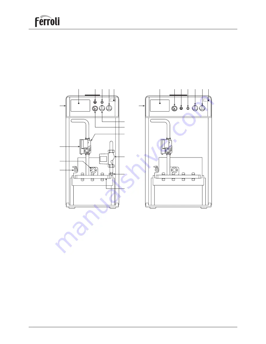
2. MAIN COMPONENTS
Fig. 1
Key
1
Boiler thermostat
2
Thermal pressure gauge
3
Flue gas thermostat cover
4
Gas valve
5
Cap (ready for mounting electronic control unit)
6
Drain valve
7
Electrode assembly
8
Control panel
9
Burner assembly
Front view of the boilers with control panel cover open
5
3
11 10
14
15
13
9
6
7
12
8
1
2
4
8
5
3
11
10 13
1
2
10
Boiler switch
11
Reset button for electronic flame control unit
12
Electronic flame control unit
13
Safety thermostat with automatic reset
14
Heating system pump (PV version)
15
Cap on fitting for filling the system (PV version)
Mod. 16-23 PV
Mod. 30-36


