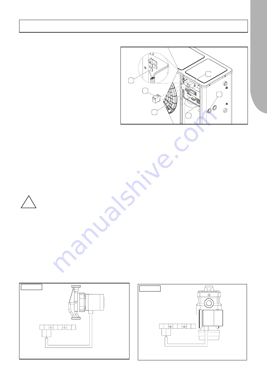
-Connect the conductors straight to the switch.
-Fix the power cable in place with a clamp (Fig. 1-E).
-Fix the protection conductor (ground wire) to the
grounding block (Fig. 1-F).
- Powering system
Single-phase units must be powered with 3 conduc-
tors (phase-neutral-ground).
Threephase units must be powered with 5 conduc-
tors (phase 1-phase 2-phase 3-neutral-ground).
The power cables of the machine’s power supply line
must therefore be off-taken from a threephase symme-
tric system equipped with neutral conductor and sepa-
rate protection conductor.
- Protection on the supply side
An automatic switch must be installed on the supply
side of the above mentioned line in order to protect
against any overcurrents and indirect contacts which
could occur as the machine operates..
It is advisable to install an automatic limiter switch
(IL)
with the minimum specifications given in tables 1 and 2.
Connections between the line and switch must be made in compliance with the current laws governing electrical safety mat-
ters, regarding the type of installation and environmental conditions in which the machine is installed.
- Protection conductor (ground wire)
The protection conductor from the electricity main must be connected straight to the ground screw, able to guarantee the equi-
potential connection of all metal grounding points and structural parts of the machine (Fig. 1-F).
- Neutral conductor
The neutral conductor that forms the line must be connected to the neutral terminal marked “
N
”, corresponding to the fourth
pin of the panel’s main disconnector.
B-STORAGE AND PUMPING MODULE
Depending on the model, the Storage and Pumping Module can be equipped with either a circulator or multiple-stage pump,
both complete with power cable.
All the electrical components in the Module (circulator/pump and electric antifreeze heating element if installed) must be con-
nected straight to the terminal board in the relative unit.
Proceed in the following way to make the connections:
-
Route the pump cable through the partition on the connection side of the chiller using the core hitches that pass through this latter.
-
Access the chiller through one of the core hitches in the connection side, connect the pump cable to the terminal board and fix
it in place with the cable clamp on the electric panel.
-Make the connections as shown in the following diagrams.
19
ENGLISH
ENGLISH
ELECTRICAL CONNECTIONS
D
E
B
F
C
!
NOTE:
If the power cable has been damaged, stop the machine if it is operating, and have the flex immediately repla-
ced by an authorized electrician.
Fig.1
MORSETITERA REFRIGERATORE
P1P2
R1A R1A
ALL ALL
MARRONE
BL
U
GL
VRD
GL
VRD
BL
U
MARRONE
ALL
ALL
R1A
R1A
P2
P1
MORSETITERA REFRIGERATORE
Mod. 30-33 High head and mod. 55 Standard Version
Mod. 30-33 in the Standard Version
MULTIPLE STAGE PUMP
CIRCULATOR
MC743_0
MC743_0


