26
ENGLISH
ENGLISH
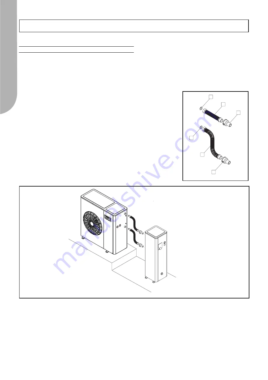
Connection with Flexible wet couplings (KT)
Allow the components to be quickly installed, even when the connections are slightly misaligned, also limiting the extent to which
vibrations are transmitted from the Unit to the Storage Module and, consequently, to the system.
THE KIT COMPRISES:
-2 (two) flexible, extensible pipes (length: min 185 - max 400 mm) in stainless steel M-F 1” (fig. 1-A)
-2 (two) ¾”-1” M-F reductions (Fig. 1-B) (not required for Storage Modules 30-33-55)
-2 (two) 1” seals (Fig. 1-C)
-1 (one) instruction manual
Instructions about how to install the quick connections are given further on (Fig. 2):
1)Disconnect the units from the electric power source.
2)Move the storage tank near to the chiller so as to take the measurements for the hose
pipes.
3)Extend and shape the hose pipes (Fig. 1-A) as shown in Fig. 2.
4)A: only if the storage tank couplings are the ¾” F type: screw the two supplied ¾”-1” M-
F reductions (Fig. 1-B) to the storage tank itself, applying sealant to the two threads.
B: if the storage tank couplings are the 1” F type, the two reductions need not be assem-
bled (Fig. 1-B).
5)Screw the male threaded end of the hose pipes to the storage tank, applying sealant to
the two threads.
6)Screw the female fitting of the extensible tubes to the male connections of the chiller,
with the supplied seals in between (Fig.1-C).
7)Insulate the hose pipes with insulating material.
8)Connect the units back to the electric power source.
WET CONNECTIONS
B
B
A
C
A
C
Fig.1
Fig.2


