background image

SIS. ECOTECH 2 F

cod. 3541B140 - 11/2011  (Rev. 00)

%

IT

 - ISTRUZIONI DI MONTAGGIO

GB

 - INSTALLATION INSTRUCTIONS

Summary of Contents for SIS. ECOTECH 2 F 160

Page 1: ...SIS ECOTECH 2 F cod 3541B140 11 2011 Rev 00 IT ISTRUZIONI DI MONTAGGIO GB INSTALLATION INSTRUCTIONS...

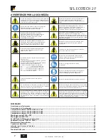
Page 2: ...rti di conduzione della tensione sono protette mediante copertura oppure sbarramento vengono rispettate le distanze di sicurezza 1 m con tensione di 1000 Volt 3 m con tensione da 1000 a 11000 Volt 4 m...

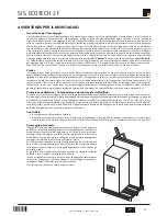
Page 3: ...egioni esposte a forti venti In questi casi occorre tener conto di tutte le caratteristiche del luogo di montaggio f hn effetto ugello formazione di vortici ecc che possono comportare maggiori solleci...

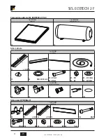
Page 4: ...25 12X M8 4X M12 24X M8 8X 13x24 Composizione sistema SIS ECOTECH 2 F 160 Cod 0XCK1RXA Ecotop VF 2 Cod GRHXAW0A Bollitore Ecotech 2 F 160 1X 1X Cod 072209X0 Kit accessori L 2X L 2195 1X 1X 1X 1X 6X DE...

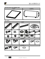
Page 5: ...5 12X M8 4X M12 24X M8 8X 13x24 Composizione sistema SIS ECOTECH 2 F 220 Cod 0XCK2RXA Ecotop VF 2 3 Cod GRHXBW0A Bollitore Ecotech 2 F220 1X 1X Cod 072210X0 Kit accessori L 2X L 2495 1X 1X 1X 1X 6X DE...

Page 6: ...Bollitore Ecotech 2 F 280 2X 1X Cod 072211X0 Kit accessori L L 2X L 2395 2X L 2195 1X 1X 4X M12x45 1X 6X DE23 5 DI18 5x1 5 4X 12X M8x75 6X M8x45 4X M12 18X M8 24X M8 12X 8x24 8X 13x37 Cod 072166X0 Ki...

Page 7: ...7 Cod 3541B140 11 2011 Rev 00 SIS ECOTECH 2 F IT Tetto piano OPZIONALE Cod 072213X0 Kit GVN F 280 L L 6X 2X L 1495 2X L 1195 1X 12X M8x75 4X M12x25 12X M8 4X M12 24X M8 8X 13x24...

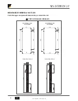
Page 8: ...5 2195 2495 12 5 250 60 12 5 250 2195 12 5 250 60 12 5 250 MONTAGGIO MODELLI 160 E 220 Punti di fissaggio consigliati sulla falda del tetto per modelli 160 e 220 PUNTI DI FISSAGGIO CONSIGLIATI DIMENSI...

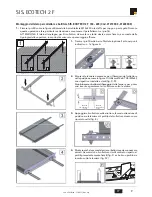
Page 9: ...ttenzionedi posizionare la lamiera sul profilo del collettore stesso come riportato nella fig E 4 Montareanchelasecondalamiera ibulloninondevonoessere serrati Accurarsi che il collettore risulti centr...

Page 10: ...sopra i profili a C PUNTI DI FISSAGGIO UTILIZZATI PER STAFFAGGIO BOLLITORE VITI TE M12x45 6 Allineare i fori e fissare con le viti M12x45 come in figura G Utilizzare le rondelle in dotazione per fissa...

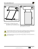
Page 11: ...con OR per montaggio errato utilizzo di componenti non conformi o manomissione pu causare l irreparabile versamento di liquido dell impianto all interno del pannello Questo pu compromettere in modo i...

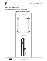
Page 12: ...v 00 IT 1300 40 250 1905 1300 2195 2195 12 5 250 400 60 12 5 400 40 MONTAGGIO MODELLO 280 Punti di fissaggio consigliati sulla falda del tetto per modelli 280 DIMENSIONE PROFILO SIS ECOTECH 2 F 280 Co...

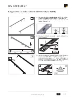
Page 13: ...Fissare i profili sulle barre filettate optional nei punti indicati in figura 1 A 2 Montare le staffette antiscivolo e fissarle utilizzando le viti TCEI M8x75 10 Nm 3 Inserire le prime due morse all...

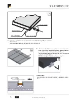
Page 14: ...3541B140 11 2011 Rev 00 IT 105 5 1300 90 90 1310 517 5 517 5 517 5 517 5 4 Fissare i profili fig 4 su quelli fissati precedentemente sul tetto ATTENZIONE ATTENERSI ALLE MISURE RIPORTATE SUL DISEGNO N...

Page 15: ...lettore verificandone l appoggio alle morse ed alle staffette antiscivolo fig D Inserire la seconda coppia di morse ed incastrarle nella cavit nei fianchi del collettore fig E Preparare montate anche...

Page 16: ...serire la clip di fissaggio nell apposita sede sui raccordi in plastica del 2 collettore Montare la coppia di morse successive fig F ATTENZIONE LA DISTANZA TRA I COLLETTORI DEVE ESSERE DI CIRCA 41mm O...

Page 17: ...TI PER STAFFAGGIO BOLLITORE VITI TE M12x45 11 Serraretuttelevitiperbloccarelemorseediconseguenza i collettori e il bollitore Coppia di serraggio max 20Nm 1 11 F H 10 Allineare i fori e fissare con le...

Page 18: ...aggio errato utilizzo di componenti non conformi o manomissione pu causare l irreparabile versamento di liquido dell impianto all interno del pannello Questo pu compromettere in modo irreversibile la...

Page 19: ...ento con aggiunta di ancoraggio ecc Attenzione La sottocostruzione a cura del committente deve essere in grado di assorbire le forze del vento che spingono sui collettori ed essere fissata in modo da...

Page 20: ...riangoli come indicato in figura 1 2c Bloccare i giunti inferiori fig 2c 2a Bloccare il giunto superiore sui profili portanti ATTENZIONE ATTENERSIALLEMISURE RIPORTATE IN fig 2a 2a 2 2a 2b 2c 2b Blocca...

Page 21: ...SIS ECOTECH 2 F IT 4 Procedere con le stesse fasi di montaggio precedentemente illustrate nell installazione su tetti inclinati 3 Fissare il controvento utilizzando le viti TE M12x20 con rispettivi d...

Page 22: ...2011 Rev 00 IT Punti di fissaggio consigliati PUNTI DI FISSAGGIO CONSIGLIATI IN CONDIZIONI DI CARICHI NORMALI X PUNTI DI FISSAGGIO CONSIGLIATI IN CONDIZIONI DI FORTI CARICHI SIS ECOTECH 2 F 160 SIS E...

Page 23: ...23 Cod 3541B140 11 2011 Rev 00 SIS ECOTECH 2 F IT ATTENZIONE Per vento 26m sec 100km h Cod 076216X0 Tiranti antivento cod 076216X0...

Page 24: ...caso scade la garanzia della resistenza elettrica Per il collegamento elettrico della resistenza necessario Rimuovere il coperchio togliendo la vite C Per il collegamento della resistenza elettrica de...

Page 25: ...cuito primario solare con le miscele acqua glicole utilizzando l attacco per la valvola di sicurezza circuito solare E Versare la miscela finch non fuoriesce tutta l aria dal circuito montare quindi l...

Page 26: ...one e il collegamento delle tubazioni per l acqua sanitaria sono operazioni a carico dell utente collegare le tubazioni dell acqua fredda A a quelle dell acqua calda B conformemente alle dispo sizioni...

Page 27: ...anitario kPa 850 850 850 Temperatura massima di funzionamento circuito sanitario C 90 90 90 Assorbitore in rame con trattamento ad alta selettivit Grado di assorbimento 95 95 95 Emissivit 5 5 5 Isolam...

Page 28: ...zburg DE 3879 DAVOS CH 5267 ATENE GR 5298 Stoccolma SE 30 Wurzburg DE 36 1 DAVOS CH 43 5 ATENE GR 63 6 SIS ECOTECH 2 F 220 250 Stoccolma SE 4100 Wurzburg DE 4762 DAVOS CH 6433 ATENE GR 6528 Stoccolma...

Page 29: ...eve essere assicurata dal cliente la piena accessibilit al prodotto in totale sicurezza secondo le norme vigenti Gli eventuali costi relativi sono a carico del cliente Esclusioni Sono escluse dalla pr...

Page 30: ...voltage conducting parts are protected by covering or barriers the safety distances are respected 1 m for 1000 Volt 3 m for 1000 to 11000 Volt 4 m for 11000 to 22000 Volt 5 m for 22000 to 38000 Volt 5...

Page 31: ...ng winds In these cases it is necessary to take into account all the characteristics of the place of installation foehn nozzle effect creation of whirlwinds etc that can involve greater stresses The c...

Page 32: ...12X M8 4X M12 24X M8 8X 13x24 Composition of system SIS ECOTECH 2 F 160 Code 0XCK1RXA Ecotop VF 2 Code GRHXAW0A Ecotech 2 F 160 hot water tank 1X 1X Code 072209X0 Accessories kit L 2X L 2195 1X 1X 1X...

Page 33: ...2X M8 4X M12 24X M8 8X 13x24 Composition of system SIS ECOTECH 2 F 220 Code 0XCK2RXA Ecotop VF 2 3 Code GRHXBW0A Ecotech 2 F 220 hot water tank 1X 1X Code 072210X0 Accessories kit L 2X L 2495 1X 1X 1X...

Page 34: ...W0A Ecotech 2 F 280 hot water tank 2X 1X Code 072211X0 Accessories kit L L 2X L 2395 2X L 2195 1X 1X 4X M12x45 1X 6X DE23 5 DI18 5x1 5 4X 12X M8x75 6X M8x45 4X M12 18X M8 24X M8 12X 8x24 8X 13x37 Code...

Page 35: ...35 Code 3541B140 11 2011 Rev 00 SIS ECOTECH 2 F GB Flat roof OPTIONAL Code 072213X0 Kit GVN F 280 L L 6X 2X L 1495 2X L 1195 1X 12X M8x75 4X M12x25 12X M8 4X M12 24X M8 8X 13x24...

Page 36: ...000 2495 2195 2495 12 5 250 60 12 5 250 2195 12 5 250 60 12 5 250 INSTALLATION OF MODELS 160 AND 220 Recommended roof pitch fixing point for models 160 and 220 RECOMMENDED FIXING POINTS PROFILE DIMENS...

Page 37: ...the structure making sure to position the sheet on the profile of the collector as shown in fig E 4 Also fit the second sheet the bolts must not be tightened Make sure the collector is centred with r...

Page 38: ...nk must be housed over the C pro files FIXING POINTS USED FOR CLAMPING HOT WATER TANK HEX HEAD SCREWS M12x45 6 AligntheholesandfixwiththeM12x45screwsasshowninfigureG Usethewasherssuppliedtofixthehotwa...

Page 39: ...g sealing system due to incorrect assembly the use of non conforming components or tampering can cause irreparable spilling of system liquid inside the panel This can permanently compro mise panel fun...

Page 40: ...2011 Rev 00 GB 1300 40 250 1905 1300 2195 2195 12 5 250 400 60 12 5 400 40 INSTALLATION OF MODEL 280 Recommended fixing points on roof pitch for models 280 PROFILE DIMENSIONS SIS ECOTECH 2 F 280 Code...

Page 41: ...profiles to the threaded bars optional at the places indicated in figure 1 A 2 Fit the anti slip brackets and fix with the M8x75 hex socket screws 10 Nm 3 Insert the first two clamps inside the profil...

Page 42: ...ode 3541B140 11 2011 Rev 00 GB 105 5 1300 90 90 1310 517 5 517 5 517 5 517 5 4 Secure the profiles fig 4 to those previously fixed on the roof ATTENTION RESPECT THE MEASUREMENTS GIVEN IN THE DRAWING N...

Page 43: ...collector carefully making sure it is resting on the clamps and anti slip brackets fig D Insert the second pair of clamps and fit them in the cavity in the sides of the collector fig E Also prepare fi...

Page 44: ...41 mm Insertthefixingclipinthespecialseatontheplasticunions of the 2nd collector Fit the next pair of clamps fig F ATTENTION THEDISTANCEBETWEENCOLLECTORSMUSTBEAPPROX 41mm O rings already fitted solar...

Page 45: ...CLAMPING THE HOT WATER TANK HEX HEAD SCREWS M12x45 11 Tighten all the screws to secure the clamps and therefore thecollectorsandthehotwaterstoragetank Tightening torque max 20Nm 1 11 F H 10 Align the...

Page 46: ...ystem due to incorrect assembly the use of non conforming components or tampering can cause irreparable spilling of system liquid inside the panel This can permanently compro mise panel functionality...

Page 47: ...slabs with anchoring etc Attention The substructure to be prepared by the customer must be able to take the force of the wind on the collectors and be fixed so as not to damage the roof The structure...

Page 48: ...en the triangles as shown in figure 1 2c Clamp the lower joints fig 2c 2a Secure the upper joint to the support profiles ATTENTION RESPECT THE MEASURE MENTS GIVEN IN fig 2a 2a 2 2a 2b 2c 2b Secure the...

Page 49: ...0 11 2011 Rev 00 SIS ECOTECH 2 F GB 4 Carry out the same steps previously described for installation on sloping roofs 3 Fix the brace using the M12x20 hex head screws with respective nuts and washers...

Page 50: ...ode 3541B140 11 2011 Rev 00 GB Recommended fixing points RECOMMENDED FIXING POINTS IN NORMAL LOAD CONDITIONS X RECOMMENDED FIXING POINTS IN HIGH LOAD CONDITIONS SIS ECOTECH 2 F 160 SIS ECOTECH 2 F 280...

Page 51: ...51 Code 3541B140 11 2011 Rev 00 SIS ECOTECH 2 F GB ATTENTION For wind 26m sec 100km h Code 076216X0 Braces code 076216X0...

Page 52: ...n this case the heating element warranty is invalidated For the heating element electrical connection Remove the cover removing screw C For the connection of the boiler heating element to the power su...

Page 53: ...ll the solar primary circuit with water glycol mixtures using the connection for the solar circuit safety valve E Add the mixture until all the air has come out the circuit then fit the solar circuit...

Page 54: ...ss of all the unions Insulation of pipes outside and inside the building by the user to insulate the external pipes use material resistant to UV rays and high temperatures 150 C to insulate the intern...

Page 55: ...elain enamelled Hot water tank cathode protection Magnesium anode Electrical heating element W 1500 1500 1500 Solar circuit connections size 3 4 3 4 3 4 DHW circuit connections size 3 4 3 4 3 4 Solar...

Page 56: ...79 DAVOS CH 5267 ATHENS GR 5298 Stockholm SE 30 Wurzburg DE 36 1 DAVOS CH 43 5 ATHENS GR 63 6 SIS ECOTECH 2 F 220 250 Stockholm SE 4100 Wurzburg DE 4762 DAVOS CH 6433 ATHENS GR 6528 Stockholm SE 29 4...

Page 57: ......

Page 58: ......

Page 59: ......

Page 60: ......

Reviews: