S.p.A.
10
SUN
VE
G
P
VE
G
P
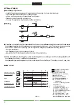
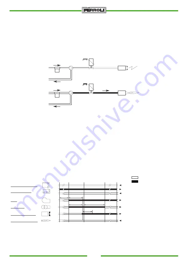
a) Once the thermostatic line has been closed, the burner motor will start operating together with the pump
the intaken heating oil will be totally conveyed towards the return side. The burner fan and ignition
transformer will also be operating and the appliance will proceed with the following phases:
- flue pre-ventilation
- pre-flushing of part of the heating oil circuit
- pre-ignition, with discharge between the tips of the electrodes.
b) At the end of the pre-flushing phase, the electromagnetic valve will open and the heating oil will reach
the injector from which it will be finely atomized.
Contact with the spark between the electrode tips will form the flame. The safety time will now start.
WORK CYCLE
SETTING AT WORK
1) Preliminary operations
- mount the pressure gauge and vacuometer on the pump (remove after start-up)
- open the gate valves along the heating oil pipe
- power the equipment by means of the main switch
- close the thermostat line (boiler/room)
- release the appliance (by depressing the red button).
2) Start-up
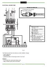
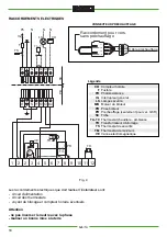
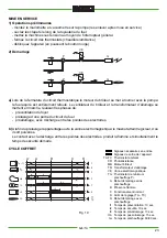
Fig. 10
A'
A
B
C
D
1
8
3
3
7
4
11
12
tw
t1
t3
t3 n
t2
Preheater with TM
Motor
Transformer
Electromagnetic valve
Photoelectric resistance
Room-boiler thermostat
TA - TC
Pr
Tm
MB
TR
VE
FR
Signals required on input
Signals on output
TA-TC Room thermostat
FR Photoelectric resistance
MB Burner motor
TR Ignition transformer
VE Electromagnetic valve
Tm Heater Pr minimum
thermostat
A Start-up without preheater
B Flame on
C Normal operation
D Adjustment stop (TA-TC)
A' Start-up with preheater
t1 Pre-ventilation time: 13 sec.
t2 Safety time: 10 sec.
t3 Pre-ignition time: 13 sec.
t3n After-ignition time: 15 sec.
tw Preheating time: 60/90 sec.


