background image

S.p.A.

9

SUN

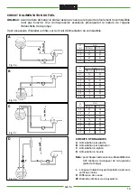
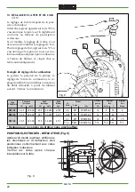
POSITION OF ELECTRODES - BAFFLE (Fig. 9)

After having mounted the injector, check
that the electrodes and baffle are correctly
positioned according to the above listed
measurements.
Always check the measurements
whenever operations are carried out on
the head.

3

1

L

45.0

°

6.5

3.5

Fig. 9

kW

23,3

34,9

46,5

kcal/h

20.000

30.000

40.000

Burner

flow rate

Kg/h

2,176

3,25

4,35

US

Gall/h

0,6

0,85

1,1

1,0

Angle

60

°

60

°

60

°

60

°

Code

3560154/0

3560134/0

3560128/0

3560127/0

Pump

pressure

Bar

12

12

12

12

Air

regulation

Tacca

5

10

15

15

kcal/h

22.200

33.200

44.400

kW

25,8

38,7

51,6

Tacca

6

10

15

18

L

18

22

27

31

*

*

*

*

*

*

*

Delivered heat

output

Head

adjustment

MODEL

BOILER

GN1.02

GN1.03

GN1.04

Heat  rate

Injector

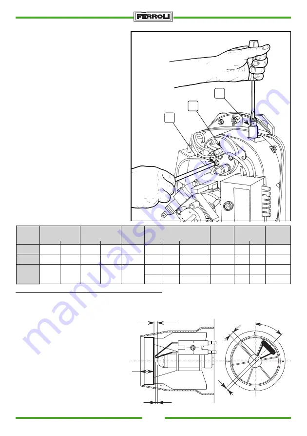
COMBUSTION HEAD AND AIR
DAMPER ADJUSTMENT (Fig. 8)

The combustion head is adjusted accord-
ing to burner flow rate. To adjust, rotate
the adjustment screw (B) clockwise or
anticlockwise until the notch on the rod
“A” coincides with the indicator.
This modifies the position of the deflec-
tor in relation to the draught tube and con-
sequently the passage of air.

The air flow rate is adjusted via screw “C”.
When the burner shuts down, the air
damper closes automatically.

EXAMPLE OF COMBUSTION REGU-
LATION

The injector, pump pressure, combustion
head adjustment and air flow rate regula-
tion must be established according to the
flow rate required by the boiler, as indi-
cated in the following chart check com-
bustion.

Fig. 8

C

A

B

* Regulations for without preheater burner version

Summary of Contents for SUN G.6

Page 1: ...INSTALLATION USE AND MAINTENANCE INSTRUCTIONS INSTRUCTIONS POUR L INSTALLATION L UTILISATION ET L ENTRETIEN S p A SUN HEATING OIL BURNER BRULEUR FUEL...

Page 2: ...eating oil fuelling line 6 Boiler assembly Pump pressure regulation 7 Choosing the injector 8 Head regulation and air flow rate adjustment Example of combustion regulation Position of electrodes baffl...

Page 3: ...etric screw Accurate air adjustment on the intake Air lock with gravity closing when the burner stops This notably limits heat dispersions when the boiler is on hold Burner is complete with a preheate...

Page 4: ...OPERATIVE RANGE OF THE BURNER V 5 17 4 P 20 15 10 5 0 16 8 3 13 18 6 15 12 11 10 9 7 2 1 14 1 Heating oil pump 2 Motor 3 Electromagnetic valve 4 Burner unit 5 Release button 6 Mechanism 7 Photoresista...

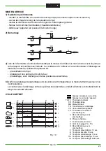
Page 5: ...VE Electromagnetic valve The following electrical connections are at the installer s charge power supply line thermostat line possible shutdown indicator light and or hour meter Attention do not swit...

Page 6: ...IC CIRCUITS A Gravity supply B Suction supply C Siphoned supply D Ring supply Nota Add 0 25 meters to the pipe length for each elbow or gate valve load losses L Total length of intake pipe including v...

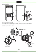
Page 7: ...e boiler using the 5 screws NR 4 M8x30 with insulating seal 1 in between Insert the burner into the boiler flange and fix it to screw 2 with nut 4 PUMP PRESSURE REGULATION DANFOSS BFP 11 R3 m h2 O Typ...

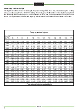
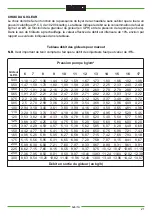
Page 8: ...3 97 4 33 4 50 4 87 5 41 5 95 6 31 7 21 8 15 9 01 10 82 1 52 1 90 2 28 2 47 2 85 3 23 3 80 4 18 4 56 4 75 5 13 5 70 6 27 6 65 7 60 8 55 9 50 11 40 10 1 59 1 99 2 39 2 59 2 99 3 39 3 99 4 38 4 78 5 00...

Page 9: ...adjustment MODEL BOILER GN1 02 GN1 03 GN1 04 Heat rate Injector COMBUSTION HEAD AND AIR DAMPER ADJUSTMENT Fig 8 The combustion head is adjusted accord ing to burner flow rate To adjust rotate the adj...

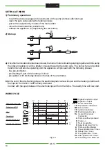
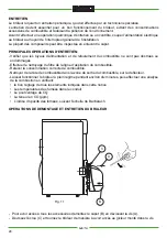
Page 10: ...WORK 1 Preliminary operations mount the pressure gauge and vacuometer on the pump remove after start up open the gate valves along the heating oil pipe power the equipment by means of the main switch...

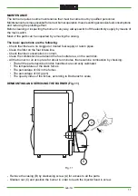
Page 11: ...upply or return pipes Clean the filter on the fuel intake line Check that fuel consumption is correct Clean the combustion head around the fuel outlet area on the swirl disk All the burner to run at t...

Page 12: ...s are closed along the heating oil line Check that the line and pump filters are clean The burner starts the flame ignites but the appliance blocks a Dirty photoelectric resi stance b Badly atomizing...

Page 13: ...S p A 13 SUN 27 26 32 31 8 30 2 1 5 13 16 15 10 23 25 34 12 23 24 9 7 17 14 11 6 28 22 29 21 20 35 19 COMPONENTS Fig 12...

Page 14: ...LHR 15 3560171 0 Transformer Brahma art TP2STPAF 55 VA 16 3560172 0 Oil feed pipe 17 3890000 0 Air regulation shaft 18 19 3560176 0 Air deflector 20 3560177 0 Air regulation 21 3560178 0 Air damper p...

Page 15: ...ordements lectriques 18 Circuit d alimentation du fuel 19 Montage sur la chaudi re R glage pression pompe 20 Choix du gicleur 21 R glage de la t te Exemple de r glage de la combustion Position lectrod...

Page 16: ...hui En utilisant des technologies modernes Ferroli a produit ces nouveaux appareils capables d optimiser le m lange air combustible au profit de rendements lev s de faibles concentrations de CO et de...

Page 17: ...g h PLAGE DE TRAVAIL DU BRULEUR V 5 17 4 P 20 15 10 5 0 16 8 3 13 18 6 15 12 11 10 9 7 2 1 14 1 Pompe fuel 2 Moteur 3 Vanne lectromagn tique 4 Corps du br leur 5 Bouton poussoir rearmement 6 Coffret d...

Page 18: ...usible FR Photor sistance IG Interrupteur g n ral LS Lampe s curit MB Moteur du br leur PB Prise br leur PR Pr chauffage seulement pour ver G6R SC Fiche TA TC Thermostat chaudi re ambiance TR Transfor...

Page 19: ...80 100 CIRCUITS HYDRALIQUES A Alimentation par gravit B Alimentation par aspiration C Alimentation siphon D Alimentation boucle Nota pourchaquecoudeouvanne ilfautadditionner 0 25 m tres la longueur de...

Page 20: ...ig 6 Placer la vis 2 M8x25 dans la plaque 3 Placer la plaque 3 sur la chaudi re et fixer par les vis 5 N 4 M8x30 en interposant une garniture isolante 1 Placer le br leur sur la plaque de la chaudi re...

Page 21: ...8 4 25 4 59 5 10 5 61 5 95 6 80 7 65 8 50 10 20 8 9 1 44 1 80 2 16 2 34 2 70 3 06 3 61 3 97 4 33 4 50 4 87 5 41 5 95 6 31 7 21 8 15 9 01 10 82 1 52 1 90 2 28 2 47 2 85 3 23 3 80 4 18 4 56 4 75 5 13 5...

Page 22: ...GN1 03 GN1 04 Debit thermique Gicleur 13 R GLAGE DE LA TETE ET DE L AIR ill 8 Le r glage de la t te d pend de la puis sance du br leur Il doit tre r gle en agissant sur la vis B en s assurant que le r...

Page 23: ...manom tre et vacuom tre sur la pompe les enlever apr s mise en service ouvrez les clapets le long de la tuyauterie du fuel mettez la machine sous tension au moyen de l interrupteur g n ral fermez le...

Page 24: ...ne sont pas obstru s ou endommag s Effectuer le nettoyage du filtre de la ligne d aspiration du combustible Relever la consommation correcte de combustible Nettoyer de la t te de combustible dans la z...

Page 25: ...rifiez la prope te du filtre du circuit et da la pompe er attention etancheite circuit fuel a Photor sistance encras see b Le gicleur pulv rise mal Le br leur ne d marre pas La flamme s allume puis l...

Page 26: ...S p A 26 SUN 27 26 32 31 8 30 2 1 5 13 16 15 10 23 25 34 12 23 24 9 7 17 14 11 6 28 22 29 21 20 35 19 BR LEUR COMPOSANTS Fig 12...

Page 27: ...3560171 0 Transformateur Brahma art TP2STPAF 55VA 16 3560172 0 Tube alimentation mazout 17 3890000 0 Arbre regulation air 18 19 3560176 0 Deflecteur air 20 3560177 0 Serrage air 21 3560178 0 Pivot ser...

Page 28: ...37047 SAN BONIFACIO VR ITALY tel 045 6139411 tlx 480172 fax 045 6100233 6100933 cod 3543308 1 04 00...

Reviews: