53
SUN M20 - M30
GB
KodL MNOOPPQO - RevL SS - TQUQSTQ
VG
PG
L1
N
T1
T2
S3
L1
N B5 T6 T7 T8
N
CT
N
TR2
VG
PG
Ph
TR1
TA
N
N
N
BZ1
LS
IG
F
TS
NC
C
NA
5
6
7
8
1
2
3
4
NC
NC
C
NA
C
NA
L
N
R
MB
MS
EA
TR
M
EI
1 2 3 4 5 6 7 8
1 2 3 4 5 6 7 8
8 7 6 5 4 3 2 1 N
1~
1 2 3 4 5 6 7 8 9
1 0 1 1 1 2
CF
PRA
BZ2
L1
N
T1
T2
S3 B4
L1
N
T1
T2
S3
3P
2no
1nc
B5
T6
T7
T8
B5
T6
T7
T8
L1
N
T1
T2
S3
L1
N
T1
T2
S3
B4
h
w
h
w
Orange
Sky blue
V
iolet
Grey
Green
Blue
White
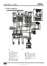
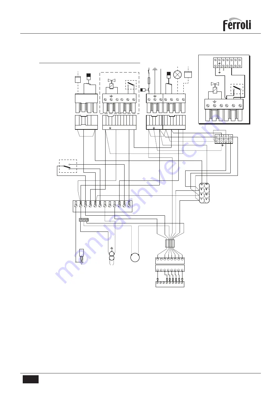
4.5 Wir ing diagram
Two-stage progressive output version
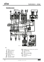
Key
F
Fuse
EI
Ionisation electrode
EA
Ignition electrode
IG
Main switch
TS
Safety thermostat
MB
Burner motor
TR
Ignition transformer
VG
Gas valve
PG
Gas pressure switch
PRA
Air pressure switch
CF
Unit terminal block
R
Relay
BZ1
Hour counter 1st stage
BZ2
Hour counter 2nd stage
TR1
Thermostat 1st stage
TR2
Thermostat 2nd stage
LS
Safety lamp
MS
Air shutter servomotor
CT
Seal test
fig. 14
With seal test
Without seal
test

