background image

SUN P7 - P12

14

EN

cod. 3540I815  -  07/2011  (Rev. 00)

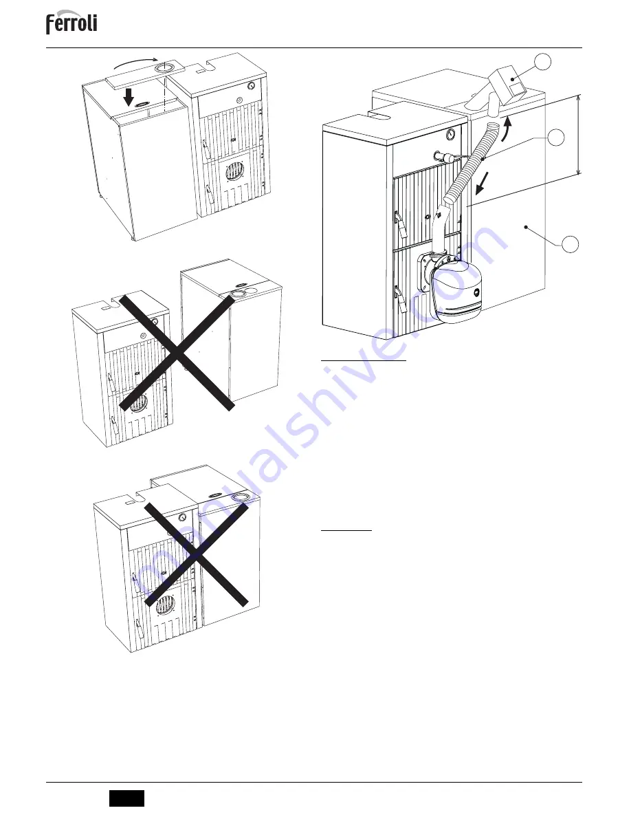
fig. 8

fig. 9

fig. 10

fig. 11

3.3 Electrical connections

The burner is equipped with a multipole terminal block for the electrical connections; re-
fer to the wiring diagram in section "

4 Technical Characteristics and Data

" for the con-

nections. The connections to be made by the installer are:

Supply line

Request contact

Auger motor connection

Temperature probe connection

The length of the connection cables must allow the burner and, if necessary, the boiler
door to be opened. If the burner power cable is damaged, it must only be replaced by
qualified personnel.

The burner must be connected to a single-phase 230 Volt-50Hz electric line.

B

Have the efficiency and suitability of the earthing system checked by profes-
sionally qualified personnel; the Manufacturer declines any liability for damage
caused by failure to earth the system. Also make sure the electrical system is
adequate for the maximum power absorbed by the unit, as specified on the boil-
er dataplate.

Make sure to respect the polarities (LINE: brown wire / NEUTRAL: blue wire /
EARTH: yellow/green wire) when making connections to the electric line.

3.4 Fuel supply

General Instructions

The burner must be fed with the type of fuel for which it is arranged, as specified on the
unit's dataplate and in the technical data table on sec. 5.3 of this manual.

The user is advised to use good quality pellets, since low quality pellets result in low heat
outputs, high ash content with subsequent need of frequent cleaning, possible early wear
of burner parts exposed to the fire, clogging of the auger and burner due to excess loose
sawdust, and operation shutdowns due to sedimentation of unburnt materials inside the
burner.

To identify quality pellets it is advisable to proceed as follows:

They must be cylinders of constant diameter and have a smooth and bright surface.

Check that the labels give the details of the quality certifications

Check that the packs are intact so that the pellets do not absorb humidity.

Pellet loading

Pellet loading can be activated within 40 minutes of switching on the power to the burner.

Within this time, the system makes available three 5-minute attempts, during which only
the auger is activated.

The burner cannot be lit during pellet loading.

Sequence:

1.

Switch on the power to the burner.

2.

Wait for the pre-ventilation stage to end.

3.

Press the programming button “P” (detail 5 - fig. 1) for 5 seconds.
- The parameter “tØ1” is displayed: identified by the message SET 01.
- Set the parameter to 1 to start the first 5-minute attempt. It can be stopped at any
time by setting the parameter 0.
- If the first attempt was insufficient, repeat the previous sequence, setting the pa-
rameter to 0 and then to 1: for the second and third loading attempt.

4.

To carry out another 3 attempts, switch power to the unit off and then on again.

OK

Y

W

X

min. 600

Summary of Contents for SUN P12

Page 1: ...IT ISTRUZIONE PER L USO L INSTALLAZIONE E LA MANUTENZIONE EN INSTRUCTIONS FOR USE INSTALLATION AND MAINTENANCE CS N VOD K POU IT INSTALACI A DR B RO INSTRUC IUNI DE UTILIZARE INSTALARE I NTRETINERE RU...

Page 2: ...e avanzata tecnologia all avanguardia elevata affidabilit e qualit costruttiva SUN P7 P12 un bruciatore di pellet la cui elevata compattezza e disegno originali lo rendono adatto all impiego sulla mag...

Page 3: ...art 4 e 6 fig 1 per modificare l inizio della 2st fascia oraria di ON esempio 12 30Premere il pulsante Programmazione P part 5 fig 1 7 12 00 e Radiatore lampeggianti 4 Utilizzare i tasti e part 4 e 6...

Page 4: ...ondo quanto prescritto dalle norme vigenti Se nello stesso locale vi sono pi bruciatori o aspiratori che possono funzionare assieme le aperture di aereazione de vono essere dimensionate per il funzion...

Page 5: ...ualit in quanto quello di bassa qualit determina basse rese caloriche alto contenuto di ceneri con conseguenti interventi di pulizia frequenti possibilit di usura precoce dei componenti del bruciatore...

Page 6: ...valvole del circuito idraulico siano aperte e che il condotto di evacuazione fumi sia libero e correttamente dimensionato Verificare la chiusura della porta caldaia in modo che la fiamma si generi sol...

Page 7: ...Soluzione A01 Blocco mancata accensione Contenitore pellets vuoto Riempire di pellets il contenitore Cavo coclea interrotto oscollegato Ripristinare il collegamento Resistenza accenditore guasta Sosti...

Page 8: ...P7 SUN P12 Portata Termica max kW 34 1 55 0 Q Portata Termica min kW 13 7 30 0 Q Portata Combustibile max kg h 7 2 11 6 Portata Combustibile min kg h 2 9 6 3 Indice di protezione elettrica IP X0D X0D...

Page 9: ...e di pressione aria A alimentazione elettrica B Coclea motore C Contatto di richiesta D Segnalazione blocco E Sblocco bruciatore OUT 15V GND DBM13 L N 4 5 6 7 8 9 10 11 12 A B E C D X2 X1 X3 218 239 1...

Page 10: ...resente garanzia i guasti e gli eventuali danni causati da trasporto non effettuato a cura dell azienda inosservanza delle istruzioni e delle avvertenze previste dall azienda produttrice e riportate s...

Page 11: ...nd quality construction SUN P7 P12 is a pellet burner whose compact size and original design make it suitable for use with the majority of solid fuel burning boilers available on the market The care t...

Page 12: ...tail 5 fig 1 7 12 00 and Radiator flashing 4 Use the and buttons details 4 and 6 fig 1 to modify the start of the 2nd OFF time band e g 14 00Press the Programming button P detail 5 fig 1 8 16 30 and R...

Page 13: ...s or exhausters that can work together in the same room the ventilation openings must be sized for simultaneous operation of all the units The place of installation must be free of flammable materials...

Page 14: ...n sec 5 3 of this manual The user is advised to use good quality pellets since low quality pellets result in low heat outputs high ash content with subsequent need of frequent cleaning possible early...

Page 15: ...or diathermic oil the water cir cuit valves are open and that the flue is free and correctly sized Check closing of the boiler door so that the flame is only generated inside the com bustion chamber C...

Page 16: ...Cure A01 No ignition shut down Pellet container empty Fill the container with pellets Auger cable broken or disconnected Restore the connection Faulty igniter resistance Replace and empty the head of...

Page 17: ...it SUN P7 SUN P12 Max heating capacity kW 34 1 55 0 Q Min heating capacity kW 13 7 30 0 Q Max fuel delivery kg h 7 2 11 6 Min fuel delivery kg h 2 9 6 3 Electrical protection rating IP X0D X0D Power v...

Page 18: ...ure transducer A electrical power supply B Motor auger C Request contact D Shutdown signal E Burner reset OUT 15V GND DBM13 L N 4 5 6 7 8 9 10 11 12 A B E C D X2 X1 X3 218 239 16 297 FR X7 INTERFACCIA...

Page 19: ...1 2 2 1 SUN P7 P12 FERROLI SUN P7 P12 SUN P7 CO NOx 2 2 3 A B C 1 7 8 17 10 1 2 3 10 A nOCU B C 8 9 16 17 18 19 10 11 12 13 14 15 1 2 3 4 5 6 7 1 1 2 3 4 5 6 7 8 9 10 11 12 Manuale On 13 14 15 16 17...

Page 20: ...4 6 1 3 ON 16 00 P 5 1 9 22 30 6 4 6 1 3 OFF 23 30 P 5 1 10 4 ON 4 OFF 11 P 5 1 3 M 2 1 5 u01 SET 01 P 5 1 4 6 1 3 1 M 2 1 5 Service P 5 1 10 t01 SET 01 P 5 1 4 6 1 3 2 P 5 1 10 06 30 08 30 12 00 12 0...

Page 21: ...00 2 5 B u02 3 3 1 B 3 2 cap 5 SUN P7 P12 B SUN P7 P12 SFL SFL L M N E 11 12 T V P R S 6 Y X W 11 u02 7 SUN P7 SUN P12 1 14 30 2 20 36 3 25 41 4 30 48 5 34 55 3 4 5 6 7 24 9 33 4 41 48 55 22 30 36 42...

Page 22: ...SUN P7 P12 38 RU cod 3540I815 07 2011 Rev 00 8 9 10 11 3 3 4 230 50 B 3 4 sez 5 3 40 3 5 1 2 3 P 5 1 5 t 1 SET 01 1 5 0 0 1 4 OK Y W X min 600...

Page 23: ...3 A 7 8 17 A B ON On 7 8 17 A C ON On 7 8 17 A A B C M 2 1 5 2 P 5 1 3 SET 03 00 A 01 B 02 C 4 6 1 3 M 2 1 5 4 2 A 1 12 12 sez 3 4 1 30 2 3 4 O2 5 9 CO 150 1000 ser vice 2 cap 2 4 CO T18 5 6 5 u02 1...

Page 24: ...2 40 RU cod 3540I815 07 2011 Rev 00 4 4 7 1 A 5 1 1 F 3 5 5 1 14 SUN P7 15 SUN P12 A01 F02 A02 A04 03 51 04 12 10 F05 F06 F10 A03 13 14 454 253 315 218 288 162 139 190 60 253 315 490 218 280 210 226 1...

Page 25: ...7 2011 Rev 00 5 2 16 1 2 3 4 5 6 7 8 85 9 10 11 12 13 5 3 SUN P7 SUN P12 34 1 55 0 Q 13 7 30 0 Q 7 2 11 6 2 9 6 3 IP X0D X0D 230 50 230 50 100 100 300 300 11 13 5 195 323 140 226 6 35 6 35 0 2 0 2 11...

Page 26: ...12 A B E C D X2 X1 X3 218 239 16 297 FR X7 INTERFACCIA UTENTE BIT01 02 34 L N 11 10 9 8 7 6 5 4 3 2 1 1 2 3 4 5 6 7 6 5 4 3 2 1 1 2 3 4 3 15 A OUT 15V GND DBM13 L N 4 5 6 7 8 9 10 11 12 A B E C D 13 1...

Page 27: ...ies with the following EU directives Low Voltage Directive 73 23 amended by 93 68 Electromagnetic Compatibility Directive 89 336 amended by 93 68 President and Legal Representative Cav del Lavoro Dant...

Page 28: ...FERROLI S p A Via Ritonda 78 a 37047 San Bonifacio Verona ITALY www ferroli it...

Reviews: