0101-8292-0, Rev. C
3-1
CV-12SLX User Manual
3
Power Supply Operation
3.1 Section Overview
This section covers the following topics:
Section 3.2 HVPS Front Panel Controls and Indicators
Section 3.3 Switches and LEDs on the FPS Front Panel
Section 3.4 Power-Up Procedure
Section 3.5 Control of Power Supply from a TemEBeam Controller (EBC)
Section 3.6 Control of Power Supply by a PLC-Based System Controller
Section 3.7 Responding to Latching Power Supply Faults
3.2 HVPS Front Panel Controls and Indicators
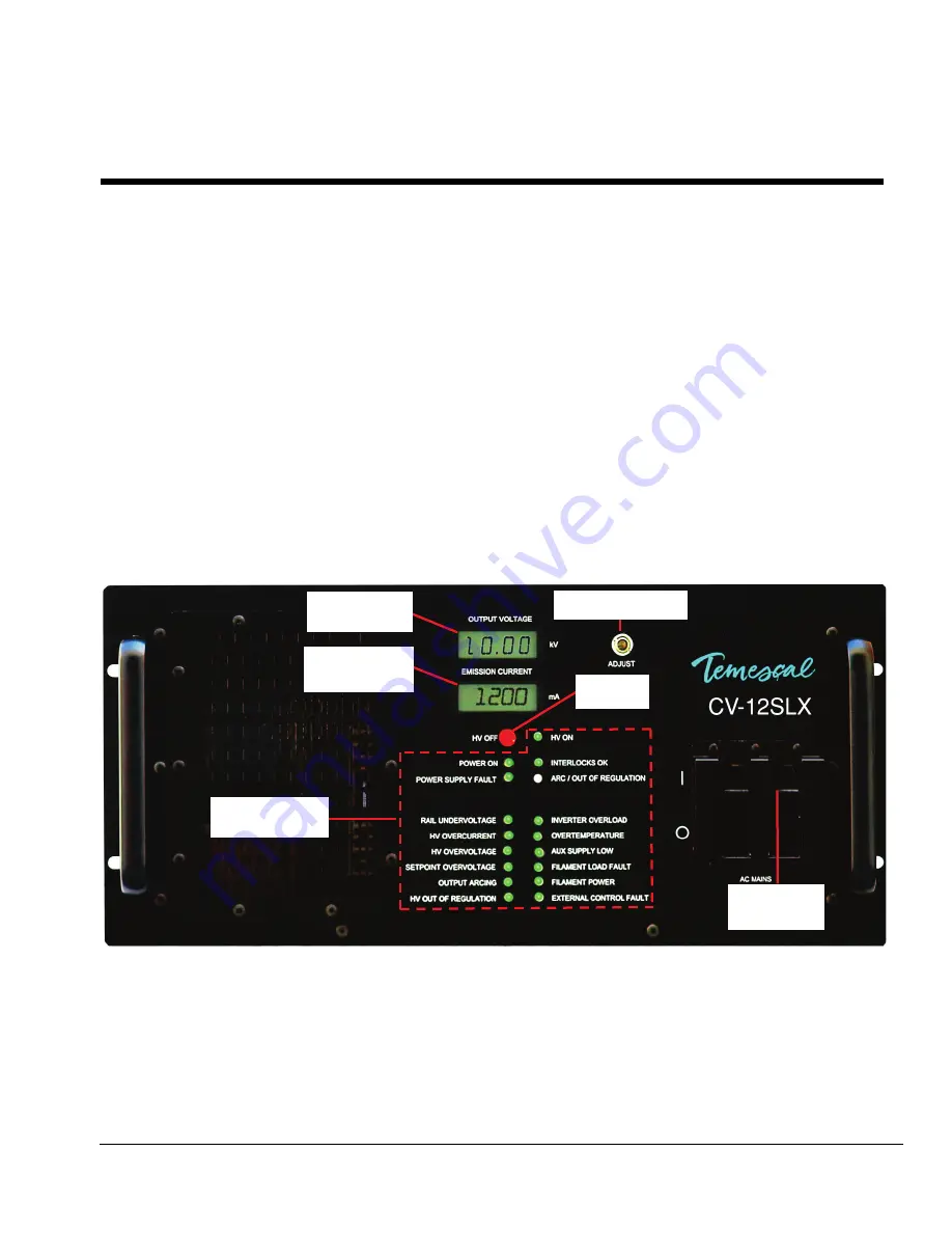
Figure 3-1 shows the controls and indicators on the front panel of the CV-12SLX HVPS. Those
features are described in detail below.
Figure 3-1 CV-12SLX HVPS Front Panel
3.2.1 HVPS Front Panel Controls
Main Circuit Breaker Switch (Labeled
AC MAINS)
High-Voltage Adjustment Pot (labeled
ADJUST
)
HV OFF
Button. This button is always active when the HVPS is powered up. Note that pushing it
when the HV is on switches it off, and pushing it when the HV is off due to a latched fault
condition resets the power supply.
Status and Fault
Indicator LEDs
HV Adjustment Pot
Main Power
Breaker
HV OFF
Button
High Voltage
Meter
Emission
Current Meter


